

Page 1

ACCULINK 3162 DSU/CSU
QUICK REFERENCE
Document No. 3162-A2-GL11-30
Page 2

Copyright 1998 Paradyne Corporation.
All rights reserved.
Printed in U.S.A.
Notice
This publication is protected by federal copyright law. No part of this publication may be
copied or distributed, transmitted, transcribed, stored in a retrieval system, or translated
into any human or computer language in any form or by any means, electronic,
mechanical, magnetic, manual or otherwise, or disclosed to third parties without the
express written permission of Paradyne Corporation, 8545 126th Ave. N., Largo,
FL 33773.
Paradyne Corporation makes no representation or warranties with respect to the
contents hereof and specifically disclaims any implied warranties of merchantability or
fitness for a particular purpose. Further, Paradyne Corporation reserves the right to
revise this publication and to make changes from time to time in the contents hereof
without obligation of Paradyne Corporation to notify any person of such revision or
changes.
Changes and enhancements to the product and to the information herein will be
documented and issued as a new release to this manual.
Warranty, Sales, and Service Information
Contact your local sales representative, service representative, or distributor directly for
any help needed. For additional information concerning warranty , sales, service, repair,
installation, documentation, training, distributor locations, or Paradyne worldwide office
locations, use one of the following methods:
Via the Internet: Visit the Paradyne World Wide W eb site at
http://www.paradyne.com
Via Telephone: Call our automated call system to receive current information via
fax or to speak with a company representative.
— Within the U.S.A., call 1-800-870-2221
— Outside the U.S.A, call 1-727-530-2340
Document Feedback
We welcome your comments and suggestions about this document. Please mail them
to Technical Publications, Paradyne Corporation, 8545 126th Ave. N., Largo, FL 33773,
or send e-mail to userdoc@eng.paradyne.com. Include the number and title of this
document in your correspondence. Please include your name and phone number if you
are willing to provide additional clarification.
Trademarks
All products and services mentioned herein are the trademarks, service marks,
registered trademarks or registered service marks of their respective owners.
Page 3

TM
ACCULINK 3162 DSU/CSU
Quick Reference
Document Number 3162-A2-GL11-30
November 1998
Product Documentation on the World Wide Web
We provide complete product documentation online. This lets you search the
documentation for specific topics and print only what you need, reducing the waste of
surplus printing. It also helps us maintain competitive prices for our products.
Complete documentation for this product is available at www.paradyne.com.
Select
Service & Support → Technical Manuals → T1/E1 Digital Access Devices.
Select the following document:
3162-A2-GB20
ACCULINK 3162 Data Service Unit/Channel Service Unit User’s Guide
To request a paper copy of a Paradyne document:
Within the U.S.A., call 1-800-P ARADYNE (1-800-727-2396)
Outside the U.S.A., call 1-727-530-8623
Before installing the DSU/CSU, read the
page 18.
Important Safety Instructions
1
beginning on
Page 4
Quick Start Procedure
The following procedure is for experienced DSU/CSU users who are familiar with the
3162 DSU/CSU installation process and have no special requirements for their
application. See the
Guide
for more information.
1. Attach the power cord to the rear of the DSU/CSU and the other end to a grounded
1 15 Vac power outlet.
2. Attach the 3162 DSU/CSU network connection to the T1 network using the
appropriate cable. Attach the 3162 DSU/CSU to the customer premises equipment
via the DTE (DSX-1) and/or port connectors.
3. Power on the DSU/CSU to perform the power-up self-test.
ACCULINK 3162 Data Service Unit/Channel Service Unit User’s
NETWORK
POWER
COM
Port
PORT 2
PORT 1
NEC
CLASS 2
CAUTION:
AUX PORT OR COM PORT MUST NOT BE CONNECTED TO PSTN OR T1 NETWORK
INPUT
Power
Network
Port
AUX
COM
EXT. CLOCK
DSX-1
NETWORK
Terminal
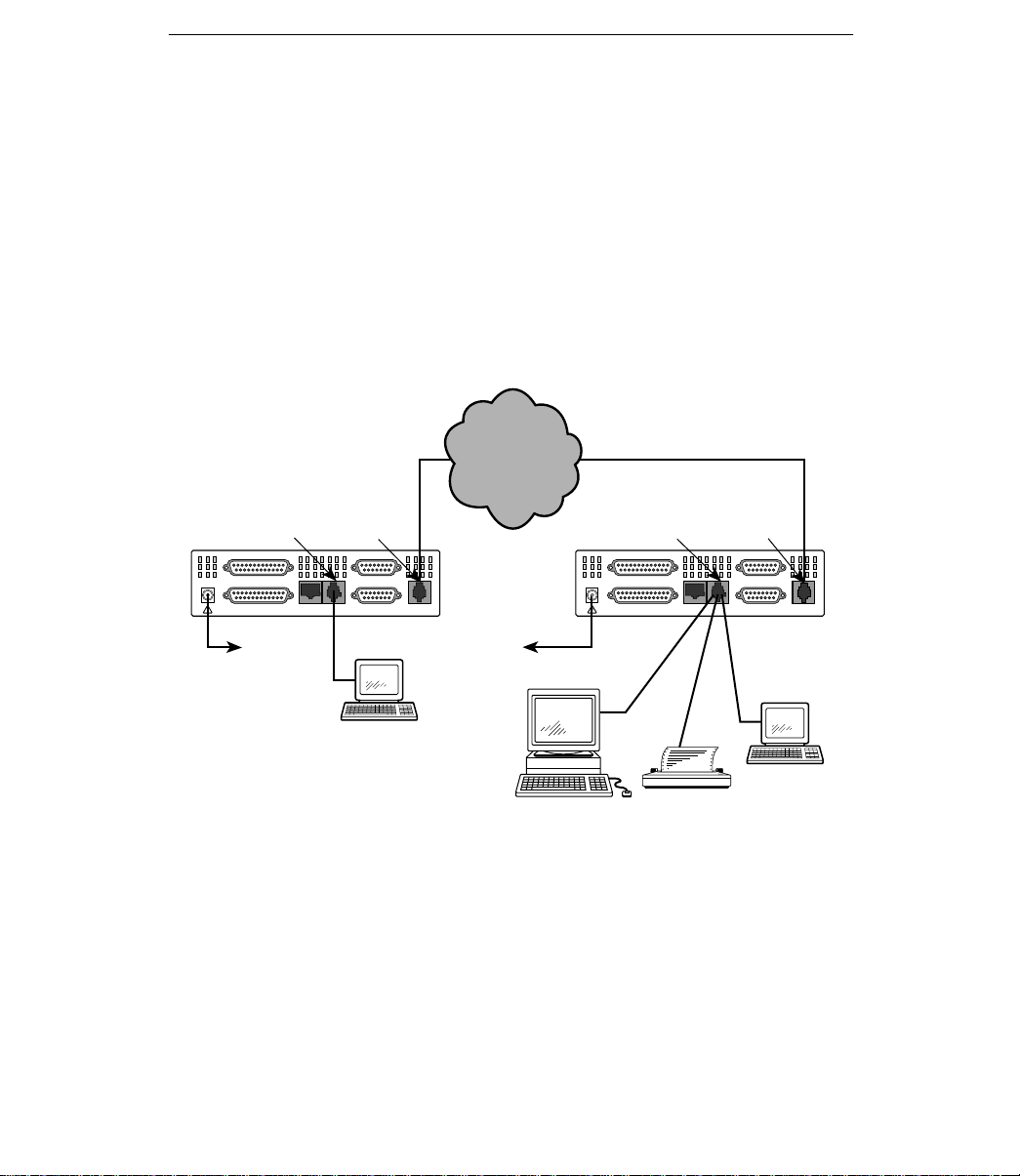
Cabling Examples
3162
DSU/CSU
DSU/CSU
Power
SNMP
Manager
3162
POWER
COM
Port
PORT 2
PORT 1
NEC
CLASS 2
CAUTION:
AUX PORT OR COM PORT MUST NOT BE CONNECTED TO PSTN OR T1 NETWORK
INPUT
or
Network
AUX
COM
or
Port
EXT. CLOCK
DSX-1
NETWORK
Terminal
97-15575
2
Page 5

4. Depending on your application, connect the COM port to:
— An SNMP or Telnet device
— A network device such as a router
— An external LAN adapter
— The AUX port of another 316x DSU/CSU for daisy chaining
— A terminal for front panel emulation
— A printer
5. The Factory 1 configuration for ESF framing format and B8ZS line coding format is
the default configuration and is appropriate for most networks. If this configuration
does not work for you, try the Factory 2 configuration for D4 framing format and
AMI line coding format. To further customize configuration options, refer to
Changing Configuration Options
Configuration Options,
Unit User’s Guide
6. During the power-up self-test, the FAIL LED flashes, then all LEDs blink twice.
When the test is complete, verify that the DSU/CSU is functional by observing that
the OK, NETWORK SIG, and DTE SIG LEDs are lit.
7. Configure the ports and channels you intend to use and assign channels to the
network interface.
in the
.
in Chapter 3,
Operation
, and to Appendix C,
ACCULINK 3162 Data Service Unit/Channel Service
3
Page 6

Configuration Options
Configuration options are accessed from the Configuration branch of the front panel
menu.
Main
System and
Test Status
DTE Channel
Network
Channel
Display
Network DTE
Cross Connect
Status
Display
Port
Assignment
Display
Network
Status
Display
Performance
Statistics
Sync Data
Port
Sync Data
Ports
Assignments
LEDs
Network &
DTE Tests
Clear
Statistics
DTE to
Network
Identity
Sync Data
Port Tests
Copy
Ports
Test
Device
Tests
Cross
Connect
Sync Data
Port
Assignments
Communication
Port
Configuration Control
Call
Customer ID
Alarms
& Traps
Telnet
Administer
Password
Download
Management
and
Communication
Auxiliary
Port
Abort
Tests
Configuration
Edit/Display
General
Options
Clear
Assignments
External
Device
Directories
Call
Setup
User
Interface
Sessions
Monitor Jack
Start
Select
Reset
Device
Select
LEDs
Communication
Protocol
General SNMP
Management
4
SNMP NMS
Security
SNMP
Traps
97-15576
Page 7

Factory default configuration options are shown in boldface type in the following tables.
Line Framing
Selects AMI or B8ZS line coding
Provides enforcement of ones
Bit Stuffing:
AT&T TR 62411, ANSI T1-403
d
Specifies whether the FDLs
ANSI Performance
Sends ANSI Performance Report
Network Initiated
Network-initiated LLB allows LLB to
Network Initiated
Circuit Identifier:
Specifies the transmission vendor s
Table 1. Network Interface Configuration Options
Option Factory 1 Factory 2 Comments/Description
Line Framing
Format:
Line Coding Format:
Bit Stuffing:
Line Build Out (LBO):
Management Link:
ANSI Performance
Report Messages:
Network Initiated
LLB:
Network Initiated
PLB:
Circuit Identifier:
D4 D4
ESF ESF
AMI AMI
B8ZS B8ZS
62411 62411
Part68 Part68
Disable Disable
0.0 0.0
–7.5 –7.5
–15 –15
–22.5 –22.5
Enable Enable
Disable Disable
Enable Enable
Disable Disable
Enable Enable
Disable Disable
Enable Enable Network-initiated PLB allows PLB
Disable Disable
[T ext Field] [Text Field]
Clear Clear
Selects D4 or ESF framing format.
Selects AMI or B8ZS line coding
format.
Provides enforcement of ones
density protection per
AT&T TR 62411
FCC Part 68 Technical Publication.
Provides Line Build Out in dB.
Specifies whether the FDL’s
Management Link is enabled.
Sends ANSI Performance Report
Messages.
Network-initiated LLB allows LLB to
be controlled by inband LLB codes.
to be controlled by FDL PLB
messages.
Specifies the transmission vendor’s
circuit identifier.
ANSI T1-403
and
, an
5
Page 8

Table 2. DTE Interface Configuration Options
Enables the use of the DTE
g
Li
g
Selects AMI
B8ZS li
bilit
All
DLB
l
Send All Ones on
gg
p
Option Factory 1 Factory 2 Comments/Description
Interface Status:
Line Framin
ne Framing
Format:
Line Coding Format:
Line Equalization:
DTE LB on External
Contact:
Send All Ones on
DTE Failure:
Enable Enable
Disable Disable
D4 D4
ESF ESF
AMI AMI
B8ZS B8ZS
0–133 0–133
133–266 133–266
266–399 266–399
399–533 399–533
533–655 533–655
Enable Enable
Disable Disable
Enable Enable
Disable Disable
Line 1 Displays: Line 2 Displays: Meaning Comments/Description
DTE Signaling
D01 D02... D24:
RBS
None Data Channel
Voice
Channel
Enables the use of the DTE
Drop/Insert port.
Selects D4 or ESF framing format.
Selects AMI or B8ZS line codin
format.
Provides selectable extended DTE
range capa
ran
Allows control of DLB on external
contact closure.
Sends all ones on channels
allocated to the network T1 on
LOS, LOF, or AIS.
Specifies which channels from the
DTE Drop/Insert interface are
voice channels and should pass
RBS information to the network.
or
e ca
abilit
ows control of
.
y.
ne coding
on externa
6
Page 9

Table 3. Synchronous Data Port Configuration Options (1 of 2)
Sel
EIA
Enabl
ith
T
k
Embedded Dat
S
ifi
d
EDL M
t
S
ifi
EDL
Select
I
d
All
All
(DTE) T1
eady
p,
Net
Network initiated DCLB, allows
5 o ( S ) codes
Option Factory 1 Factory 2 Comments/Description
E530 E530
Port Type:
Port Base Rate:
Transmit Clock
ransmit Cloc
Source:
Embedded Data
Link:
EDL Management
Link:
Invert Transmit
Clock:
Invert Transmit and
nvert Transmit an
Received Data:
Send All Ones on
Data Port Not
Ready:
a
anagemen
V.35 V.35
RS449 RS449
X.21 X.21
Nx64 Nx64
Nx56 Nx56
Internal Internal
External External
Enable Enable
Disable Disable
Disable Disable
Enable Enable
Enable Enable
Disable Disable
Enable Enable
Disable Disable
Disable Disable
DTR DTR
RTS RTS
Both Both
Selects the
ects the port type:
V.35, RS449, or X.21.
Enables the port to either Nx56 or
Nx64 rates.
Selects whether the transmitted
data clock is internal (TXC) or
external (XTXC).
Specifies whether the Embedded
pec
Data Link is enabled.
Specifies whether the EDL
pec
Management Link is Enabled.
Selects phase inversion of the
transmit clock (TXC).
Allows the data on the port to be
ows the data on the port to be
inverted.
All ones sent to network (DTE) T1
ones sent to network
when DTR or RTS interrupted.
ort t
e: EIA-530A
-530A,
es the port to e
es whether the Embedde
es whether the
s phase inversion of the
er Nx56 or
Action on Network
Yellow Alarm:
Network Init. Data
work Init. Data
Channel Loopback:
None None
Halt Halt
Disable Disable
V.54 V.54
FT1 FT1
Both Both
7
Data port remains enabled, or is
disabled, on receiving Yellow on
network T1.
Network-initiated DCLB, allows
DCLB to be controlled by inband
V.54 or FT1 (ANSI) codes.
Page 10

Table 3. Synchronous Data Port Configuration Options (2 of 2)
Port (DTE) Initiated
p,
epo by ee e a
p
Sascs
sascs
p
E
to th
Option Comments/DescriptionFactory 2Factory 1
Disable Disable
Port (DTE) Initiated
Loopbacks:
Near-End
Performance
Statistics:
Far-End
Performance
Statistics:
Excessive Error Rate
xcessive Error Rate
Threshold:
DTLB DTLB
DCLB DCLB
Both Both
Disable Disable
Maint Maint
Send Send
Both Both
Disable Disable
Maint Maint
10E–4 10E–4
10E–5 10E–5
10E–6 10E–6
10E–7 10E–7
10E–8 10E–8
10E–9 10E–9
Port-initiated Loopbacks, allows
Loopbacks to be initiated through
the port by the external DTE.
Specifies whether the device will
maintain near-end performance
statistics.
Specifies whether the device will
maintain far-end performance
statistics.
Selects the error rate threshold for
Excessive Error Rate Alarm.
Table 4. Cross Connect – DTE to Network Assignment Options
Line 1 Displays: Line 2 Displays: Meaning Comments/Description
Available
Assigned
N01 N02... N24:
DTE01
DTE02
.
DTE24
DS0 channel is
unallocated.
DS0 channel is
allocated to a
synchronous
data port.
DS0 channel
allocated to
DTE Drop/Insert
interface DS0
channel 01–24.
8
Assigns DS0 channels from the
DTE Drop/Insert (DSX-1) interface
e network interface.
to the network interface.
Page 11

Table 5. Cross Connect – Sync Data Port Assignment Options
Assign T o:
the Network or DSX 1 T1 interface,
Assign By:
assigned: contiguous blocks,
Option Factory 1 Factory 2 Comments/Description
Assign T o:
Assign By:
Port Data Rate:
Network Network
DTE DTE
Port Port
Block Block
ACAMI ACAMI
Chan Chan
64 (56)
128 (112)
192 (168)
256 (224)
320 (280)
384 (336)
448 (392)
512 (448)
576 (504)
640 (560)
704 (616)
768 (672)
832 (728)
896 (784)
960 (840)
1024 (896)
1088 (952)
1152 (1008)
1216 (1064)
1280 (1120)
1344 (1176)
1408 (1232)
1472 (1288)
1536 (1344)
64 (56)
128 (112)
192 (168)
256 (224)
320 (280)
384 (336)
448 (392)
512 (448)
576 (504)
640 (560)
704 (616)
768 (672)
832 (728)
896 (784)
960 (840)
1024 (896)
1088 (952)
1152 (1008)
1216 (1064)
1280 (1120)
1344 (1176)
1408 (1232)
1472 (1288)
1536 (1344)
Assigns this port to channels on
the Network or DSX-1 T1 interface,
or to another port.
Determines how channels are
assigned: contiguous blocks,
ACAMI or individual channels.
Selects the data rate for the port.
The possible rates depend on
whether the port is configured for
Nx56 or Nx64.
This configuration option only
appears if the “Assigned By”
configuration option is Block or
ACAMI.
Line 1 Displays: Line 2 Displays: Meaning Comments/Description
N1 N2 N3 ...... N24:
(If assigned to NET)
D1 D2 D3 ..... D24:
D1 D2 D3 ..... D24:
(If assigned to DTE)
P1
P2
D01, D02... D24
N01, N02... N24
Channel assigned
to port 1 or 2
Channel assigned
to this DTE
channel
Channel assigned
to this NET
channel
9
Designates the DS0 channel to
allocate to this port.
Page 12

Table 6. General Configuration Options
G
Yell
Allows bypass of self-test on
p
Specifies the duration of
es s
S
used as the master clock for the
External Clock Rate:
if
Controls how the COM port is
Controls whether the COM port is
Controls whether the COM port
Option Factory 1 Factory 2 Comments/Description
Generate Yellow
enerate Yellow
Alarm Signals:
-
Self-Test:
Test Timeout:
T est Duration:
T est Duration:
Primary Clock
ource:
Source:
External Clock Rate:
Enable Enable
Disable Disable
Enable Enable
Disable Disable
Enable Enable
Disable Disable
10 10
Up Up
Down Down
Save Save
Network Network
DTE DTE
Internal Internal
External External
Port 1 Port 1
2048 2048
1544 1544
8 8
Yellow alarm is generated by the
ow alarm is generated by the
DSU/CSU on LOS, LOF, or AIS.
Allows bypass of self-test on
initialization.
Specifies whether the durations of
user-initiated tests are limited by
T st Duration.
Specifies the duration of
user-initiated loopback and pattern
tests.
Selects the clock source to be
used as the master clock for the
DSU/CSU.
Selects the clock rate of the source
external.
if external.
Table 7. User Interface – Communication Port Configuration Options (1 of 2)
Option Factory 1 Factory 2 Comments/Description
Port Use:
Port Type:
Clock Source:
Mgmt Mgmt
ASCII ASCII
Daisy Daisy
Terminal Terminal
Asynchronous Asynchronous
Synchronous Synchronous
Internal Internal
External External
10
Controls how the COM port is
used.
Controls whether the COM port is
synchronous or asynchronous.
Controls whether the COM port
uses an internal or external clock.
Page 13

Table 7. User Interface – Communication Port Configuration Options (2 of 2)
Selects the character length for the
py p
the COM
I
l
S
ifi
COM
t
Controls whether a password is
p
(1 to 60 minutes) that
Option Comments/DescriptionFactory 2Factory 1
1.2 1.2
2.4 2.4
4.8 4.8
Data Rate:
Character Length:
Parity:
Stop Bits:
9.6 9.6
14.4 14.4
19.2 19.2
38.4 38.4
7 7
8 8
None None
Even Even
Odd Odd
1 1
1.5 1.5
2 2
Selects the bit rate for the COM
port.
Selects the character length for the
COM port.
Selects the parity for the COM port.
Selects the number of stop bits for
the COM
ort.
port.
Ignore Control
gnore Contro
Leads:
Password Required:
Inactivity Timeout:
Disconnect Time:
Disconnect Time:
Disable Disable
DTR DTR
Enable Enable
Disable Disable
Enable Enable
Disable Disable
5 5
Up Up
Down Down
Save Save
11
Specifies whether the COM port
pec
es whether the
ignores DTR.
Controls whether a password is
required during a call setup.
Specifies whether the
communication port disconnects
after a certain period of inactivity.
Specifies the period of inactivity
1 to 60 minutes
disconnect if Inactivity Timeout is
enabled.
enabled.
that causes a
por
causes a
Page 14

Table 8. User Interface – External Device Configuration Options
Controls whether no commands,
C
Connect Indication
20 characters used to determine
Escape Sequence
user defined escape sequence
Option Factory 1 Factory 2 Comments/Description
External Device
ommands:
Commands:
-
Dial-In Access:
Connect Prefix:
Connect Indication
String:
Escape Sequence:
Escape Sequence
Delay (sec):
Disconnect String:
Disable Disable
AT AT
Other Other
Enable Enable
Disable Disable
[T ext Field] [Text Field]
Clear Clear
[T ext Field] [Text Field]
Clear Clear
[T ext Field] [Text Field]
Clear Clear
None None
0.2 0.2
0.4 0.4
0.6 0.6
0.8 0.8
1.0 1.0
[T ext Field] [Text Field]
Clear Clear
Controls whether no commands,
AT commands, or
user-configurable commands are
user-configurable commands are
sent out the COM port.
Controls whether dial-in access is
allowed from the external device
connected to the COM port.
Allows you to enter up to
20 characters to be used with the
dial directory phone number.
Allows you to enter up to
20 characters used to determine
whether a connection has been
established.
Allows you to enter up to
20 characters to identify the COM
port’s escape sequence.
Specifies the delay in seconds
required before and after the
user-defined escape sequence.
Allows you to enter up to
20 characters to be used as the
COM port’s disconnect string.
.
12
Page 15

Table 9. User Interface – Telnet Sessions Configuration Options
p
S
ifi
p
Disconnect Time:
60 minutes) that causes a
used
Configures the bit rate for the
Option Factory 1 Factory 2 Comments/Description
T elnet Session:
Password Required:
Inactivity Timeout:
Disconnect Time:
Enable Enable
Disable Disable
Enable Enable
Disable Disable
Enable Enable
Disable Disable
5 5
1–60 1–60
Specifies whether the DSU/CSU
responds to T elnet session
requests.
Specifies whether a password is
pec
es whether a password is
required for T elnet sessions.
Specifies whether a T elnet session
disconnects after a certain period
of inactivity.
The period of inactivity (1 to
60 minutes) that causes a
disconnect if Inactivity Timeout is
enabled.
Table 10. User Interface – Auxiliary Port Configuration Options
Option Factory 1 Factory 2 Comments/Description
None None
Port Use:
Data Rate (Kbps):
Mgmt Mgmt
Daisy Daisy
9.6 9.6
14.4 14.4
19.2 19.2
38.4 38.4
Controls how the auxiliary port is
.
used.
Configures the bit rate for the
auxiliary port.
13
Page 16

Table 11. Alarm Configuration Options
p
Al
p
p
pgg
Ti
between successive alarm
Alt
t
y
Option Factory 1 Factory 2 Comments/Description
ASCII Alarm
ASCII Alarm
Messages:
Alarm & Tra
arm & Trap
Dial-Out:
Trap Disconnect:
Call Retry:
Dial Out Delay
min
:
me (min):
Time
Alternate Dial-Out
ernate Dial-Ou
Directory:
Disable Disable Does not display alarm messages.
Com Com
Enable Enable
Disable Disable
Enable Enable
Disable Disable
Enable Enable
Disable Disable
1–4 1–4
5 5
6–10 6–10
None None The alternate dial-out directory to
1–5 1–5
Sends alarm messages to
COM port.
Provides the option to allow
automatic dial-out to send alarm
messages on MODEM port.
Specifies whether the modem
connection will disconnect after a
trap is sent.
Specifies whether an outgoing call
is retried on a busy or failed call
attempt.
The time (in minutes) to delay
between successive alarm
dial-outs or retry attempts.
use if a call to the primary number
cannot be completed.
14
Page 17

Table 12. Management and Communication – Communication Protocol
The IP address needed to access
The Subnet Mask needed to
Destinati
destinati
Communications
p
Communication Port
access the device when the Port
port when the Port Use
Auxili
Auxili
to access the device when the Port
Configuration Options
Option Factory 1 Factory 2 Comments/Description
Node IP Adr:
Node Subnet Mask:
Default Network
on:
Destination:
Communications
Port IP Address:
Communication Port
Subnet Mask:
Com Link Protocol:
Auxiliary Port
ary Port
IP Address:
Auxiliary Port
ary Port
Subnet Mask:
[T ext Field] [Text Field]
Clear Clear
[T ext Field] [Text Field]
Clear Clear
None None
Com Com
Aux Aux
FDL FDL
EDL
n
[T ext Field] [Text Field]
Clear Clear
[T ext Field] [Text Field]
Clear Clear
PPP PPP
SLIP SLIP
[T ext Field] [Text Field]
Clear Clear
[T ext Field] [Text Field]
Clear Clear
EDL
n
The IP address needed to access
the DSU/CSU.
The Subnet Mask needed to
access the device.
Specifies the default network
on.
destination.
The IP address for the COM port
when the Port Use configuration
option is set to Mgmt or Daisy.
The Subnet Mask needed to
access the device when the Port
Use configuration option is set to
Mgmt or Daisy.
The link layer protocol for the COM
port when the Port Use
configuration option is set to Mgmt
or Daisy.
Specifies the alternate modem
Subnet Mask needed to access the
device when the Port Use
configuration option is set to Mgmt
or Daisy.
Specifies the Subnet Mask needed
to access the device when the Port
Use configuration option is set to
Mgmt or Daisy.
15
Page 18

Table 13. Management and Communication – General SNMP Management
p
y
The type of access allowed for
A community name that is allowed
The type of access allowed for
validates the IP address of an
Number of
The number of SNMP managers
y
yp
Configuration Options
Option Factory 1 Factory 2 Comments/Description
SNMP Management:
Community Name 1:
Name 1 Access:
Community Name 2:
Name 2 Access:
Disable Disable
Enable Enable
[T ext Field] [Text Field]
Clear Clear
Read Read
Read/Write Read/Write
[T ext Field] [Text Field]
Clear Clear
Read Read
Read/Write Read/Write
Specifies whether the DSU/CSU
responds to SNMP session
requests.
A community name that is allowed
access to this device. Defaults to
public
.
The type of access allowed for
community name 1.
A community name that is allowed
access to this device.
The type of access allowed for
community name 2.
Table 14. Management and Communication – SNMP NMS Security
Configuration Options
Option Factory 1 Factory 2 Comments/Description
Specifies whether the DSU/CSU
validates the IP address of an
SNMP manager attempting
access.
The number of SNMP managers
allowed to access the DSU/CSU.
Allows you to define or clear the
allowable IP address of an SNMP
manager.
The type of access allowed for an
SNMP manager using community
name 1.
NMS IP Validation:
Number of
Managers:
NMS n IP Address:
Access Level:
Disable Disable
Enable Enable
1 1
2–10 2–10
[T ext Field] [Text Field]
Clear Clear
Read Read
Read/Write Read/Write
16
Page 19

Table 15. Management and Communication – SNMP Traps
pp
p
Numb
Th
trap manager. This configuration
f
pgpyp
Failure or both
Ent
ifi
p
ppyp
Down, or both
Link Trap Interfaces:
,p
Configuration Options
Option Factory 1 Factory 2 Comments/Description
SNMP Traps:
Number of Tra
er of Trap
Managers:
NMS n IP Address:
Destination:
General Traps:
Enterprise Specific
erprise Spec
Traps:
Link Traps:
Link Trap Interfaces:
c
Enable Enable
Disable Disable
1 1
2–6 2–6
[T ext Field] [Text Field]
Clear Clear
None None
Com Com
Aux Aux
FDL FDL
EDL
n
Disable Disable
Warm Warm Specifies the general trap types to
AuthFail AuthFail
Both Both
Enable Enable
Disable Disable
Disable Disable
Up Up Specifies the link trap type to
Down Down
Both Both
Network Network
DTE DTE
T1s T1s
Ports Ports
All All
EDL
n
Specifies whether SNMP traps are
sent over the SNMP management
link.
The number of trap managers
e number of trap managers
supported by the device.
Specifies the IP address for each
trap manager. This configuration
option is repeated for all
managers.
Specifies the network destination
Mana
or Trap Manager n.
for Tra
enable: WarmStart, Authentication
Failure or both.
Specifies whether the
enterpriseSpecific traps are
enabled.
Enable: Trap on Link Up, Link
Down, or both.
When any link trap types are
Enabled, specifies which links to
send traps for.
.
n
er n.
.
17
Page 20

Important Safety Instructions
1. Read and follow all warning notices and instructions marked on the product or
included in the manual.
2. This product is intended to be used with a 3-wire grounding type plug – a plug
which has a grounding pin. This is a safety feature. Equipment grounding is vital to
ensure safe operation. Do not defeat the purpose of the grounding type plug by
modifying the plug or using an adapter.
Prior to installation, use an outlet tester or a voltmeter to check the ac receptacle
for the presence of earth ground. If the receptacle is not properly grounded, the
installation must not continue until a qualified electrician has corrected the problem.
If a 3-wire grounding type power source is not available, consult a qualified
electrician to determine another method of grounding the equipment.
3. Slots and openings in the cabinet are provided for ventilation. To ensure reliable
operation of the product and to protect it from overheating, these slots and
openings must not be blocked or covered.
4. Do not allow anything to rest on the power cord and do not locate the product
where persons will walk on the power cord.
5. Do not attempt to service this product yourself, as opening or removing covers may
expose you to dangerous high voltage points or other risks. Refer all servicing to
qualified service personnel.
6. General purpose cables are provided with this product. Special cables, which may
be required by the regulatory inspection authority for the installation site, are the
responsibility of the customer.
7. When installed in the final configuration, the product must comply with the
applicable Safety Standards and regulatory requirements of the country in which it
is installed. If necessary , consult with the appropriate regulatory agencies and
inspection authorities to ensure compliance.
8. A rare phenomenon can create a voltage potential between the earth grounds of
two or more buildings. If products installed in separate buildings are
interconnected, the voltage potential may cause a hazardous condition. Consult a
qualified electrical consultant to determine whether or not this phenomenon exists
and, if necessary , implement corrective action prior to interconnecting the products.
9. Input power to the ac voltage configuration of this product must be provided by a
UL-listed or CSA-certified power source with a Class 2 or Limited Power Source
(LPS) output. Input power to the dc voltage configurations of this product must be
provided by a National Electric Code (NEC) or a Canadian Electric Code (CEC)
Class 2 circuit.
10. This product contains a coin cell lithium battery that is only to be replaced at the
factory. Caution: There is a danger of explosion if the battery is incorrectly
replaced. Replace only with the same type. Dispose of used batteries according to
the battery manufacturer’s instructions. Attention: Il y a danger d’explosion s’il y a
remplacement incorrect de la batterie. Remplacer uniquement avec une batterie du
même type. Mettre au rebut les batteries usagées conformément aux instructions
du fabricant.
18
Page 21

11. In addition, if the equipment is to be used with telecommunications circuits, take the
following precautions:
— Never install telephone wiring during a lightning storm.
— Never install telephone jacks in wet locations unless the jack is specifically
designed for wet locations.
— Never touch uninsulated telephone wires or terminals unless the telephone
line has been disconnected at the network interface.
— Use caution when installing or modifying telephone lines.
— Avoid using a telephone (other than a cordless type) during an electrical storm.
There may be a remote risk of electric shock from lightning.
— Do not use the telephone to report a gas leak in the vicinity of the leak.
EMI Warnings
!
WARNING:
This equipment has been tested and found to comply with the limits for a
Class A digital device, pursuant to Part 15 of the FCC rules. These limits are
designed to provide reasonable protection against harmful interference when
the equipment is operated in a commercial environment. This equipment
generates, uses, and can radiate radio frequency energy and, if not installed
and used in accordance with the instruction manual, may cause harmful
interference to radio communications. Operation of this equipment in a
residential area is likely to cause harmful interference in which case the user
will be required to correct the interference at his own expense.
The authority to operate this equipment is conditioned by the requirements
that no modifications will be made to the equipment unless the changes or
modifications are expressly approved by Paradyne Corporation.
!
WARNING:
To Users of Digital Apparatus in Canada:
This Class A digital apparatus meets all requirements of the Canadian
interference-causing equipment regulations.
Cet appareil numérique de la classe A respecte toutes les exigences du
règlement sur le matérial brouilleur du Canada.
Government Requirements and Equipment Return
Certain governments require that instructions pertaining to CSU connection to the
telephone network be included in the installation and operation manual. Specific
instructions are listed in the following sections.
19
Page 22

Notice to Users of the United States Telephone Network
1. This equipment complies with Part 68 of the FCC rules. On the equipment is a label
that contains, among other information, the FCC registration number for this
equipment. The label is on the bottom of the DSU/CSU. If requested, this
information must be provided to the telephone company .
2. The T1 network connection should be made using a Universal Service Order Code
(USOC) type RJ48C jack. The Service Order Code 6.0F should be specified to the
telephone company when ordering the T1 line. In addition, the proper Facility
Interface Code must be specified to the Telephone Company. The DSU/CSU can
be configured to support any of the following framing format and line signaling
techniques. The DSU/CSU’s configuration must correspond to the T1 line’s
parameters.
3162 DSU/CSU Facility Interface Codes
Code
04DU9-BN 1.544 Mbps superframe format (SF) without line power
04DU9-DN 1.544 Mbps SF and B8ZS without line power
04DU9-1KN 1.544 Mbps ANSI ESF without line power
04DU-1SN 1.544 Mbps ANSI ESF and B8ZS without line power
3. If the DSU/CSU causes harm to the telephone network, the telephone company will
notify you in advance that temporary discontinuance of service may be required.
But if advance notice is not practical, the telephone company will notify the
customer as soon as possible. Also, you will be advised of your right to file a
complaint with the FCC if you believe it is necessary .
4. The telephone company may make changes in its facilities, equipment, operations,
or procedures that could affect the operation of the equipment. If this happens, the
telephone company will provide advance notice in order for you to make the
necessary modifications in order to maintain uninterrupted service.
5. If you experience trouble with this equipment, please contact your sales or service
representative (as appropriate) for repair or warranty information. If the product
needs to be returned to the company service center for repair, contact them directly
for return instructions using one of the following methods:
— Via the Internet: Visit the Paradyne World Wide W eb site at
http://www.paradyne.com
— Via Telephone: Call our automated call system to receive current information
via fax or to speak with a company representative.
Within the U.S.A., call 1-800-870-2221
Outside the U.S.A., call 1-727-530-2340
If the trouble is causing harm to the telephone network, the telephone company
may request that you remove the equipment from the network until the problem is
resolved.
Description
20
Page 23

6. FCC compliant telephone line cords with modular plugs are provided with this
equipment. This equipment is designed to be connected to the telephone network
or premises wiring using a compatible modular jack which is Part 68 compliant.
Notice to Users of the Canadian Telephone Network
The Industry Canada label identifies certified equipment. This certification means that
the equipment meets telecommunications network protective, operational and safety
requirements as prescribed in the appropriate Terminal Equipment Technical
Requirements document(s). The Department does not guarantee the equipment will
operate to the user’s satisfaction.
Before installing this equipment, users should ensure that it is permissible to be
connected to the facilities of the local telecommunications company . The equipment
must also be installed using an acceptable method of connection. The customer should
be aware that compliance with the above conditions may not prevent degradation of
service in some situations.
Repairs to certified equipment should be coordinated by a representative designated by
the supplier. Any repairs or alterations made by the user to this equipment, or
equipment malfunctions, may give the telecommunications company cause to request
to disconnect the equipment.
Users should ensure for their own protection that the electrical ground connections of
the power utility , telephone lines and internal metallic water pipe system, if present, are
connected together. This precaution may be particularly important in rural areas.
CAUTION:
Users should not attempt to make such connections themselves, but should
contact the appropriate electric inspection authority , or electrician, as
appropriate.
The Ringer Equivalence Number (REN) assigned to each terminal device provides an
indication of the maximum number of terminals allowed to be connected to a telephone
interface. The termination on an interface may consist of any combination of devices
subject only to the requirement that the sum of the Ringer Equivalence Numbers of all
the devices does not exceed 5.
If your equipment is in need of repair, refer to
in the front of this document.
Warranty, Sales, and Service Information
21
 Loading...