

Page 1

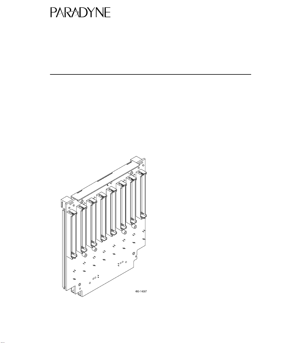
ACCULINK 3161 DSU/CSU
QUICK REFERENCE
Document No. 3161-A2-GL11-40
Page 2

Copyright 1998 Paradyne Corporation.
All rights reserved.
Printed in U.S.A.
Notice
This publication is protected by federal copyright law. No part of this publication may be
copied or distributed, transmitted, transcribed, stored in a retrieval system, or translated
into any human or computer language in any form or by any means, electronic,
mechanical, magnetic, manual or otherwise, or disclosed to third parties without the
express written permission of Paradyne Corporation, 8545 126th Avenue North, P.O.
Box 2826, Largo, Florida 33779-2826.
Paradyne Corporation makes no representation or warranties with respect to the
contents hereof and specifically disclaims any implied warranties of merchantability or
fitness for a particular purpose. Further, Paradyne Corporation reserves the right to
revise this publication and to make changes from time to time in the contents hereof
without obligation of Paradyne Corporation to notify any person of such revision or
changes.
Changes and enhancements to the product and to the information herein will be
documented and issued as a new release to this manual.
Warranty, Sales, and Service Information
Contact your sales or service representative directly for any help needed. For additional
information concerning warranty, sales, service, repair, installation, documentation, or
training, use one of the following methods:
Via the Internet: Visit the Paradyne World Wide W eb site at
http://www.paradyne.com
Via Telephone: Call our automated call system to receive current information via
fax or to speak with a company representative.
— Within the U.S.A., call 1-800-870-2221
— International, call 727-530-2340
T rademarks
All products and services mentioned herein are the trademarks, service marks,
registered trademarks or registered service marks of their respective owners.
Page 3
TM
ACCULINK 3161 DSU/CSU
Quick Reference
Document Number 3161-A2-GL11-40
February 1998
Quick Start Procedure
The following procedure is for experienced DSU/CSU users who are familiar with the
3161 DSU/CSU installation process and have no special requirements for their
application. See the
Operator’s Guide
Auxiliary Backplane.
1. Install the Auxiliary Backplane onto the 3000 Series Carrier. See the
3151 CSU and 3161 DSU/CSU General Information Guide
installation procedures.
ACCULINK 316x Data Service Unit/Channel Service Unit
(3160-A2-GB21) for more information. A copy is included with the
ACCULINK
(3100-A2-GK40) for
2. Attach the DTE cable (DB15) and/or port cables (DB25) to the appropriate
connectors on the Auxiliary Backplane. See the
Installation Manual
Connect the other end of the DTE cable to the customer premises equipment.
(3000-A2-GA31) for detailed cable and connector information.
1
COMSPHERE 3000 Series Carrier
Page 4
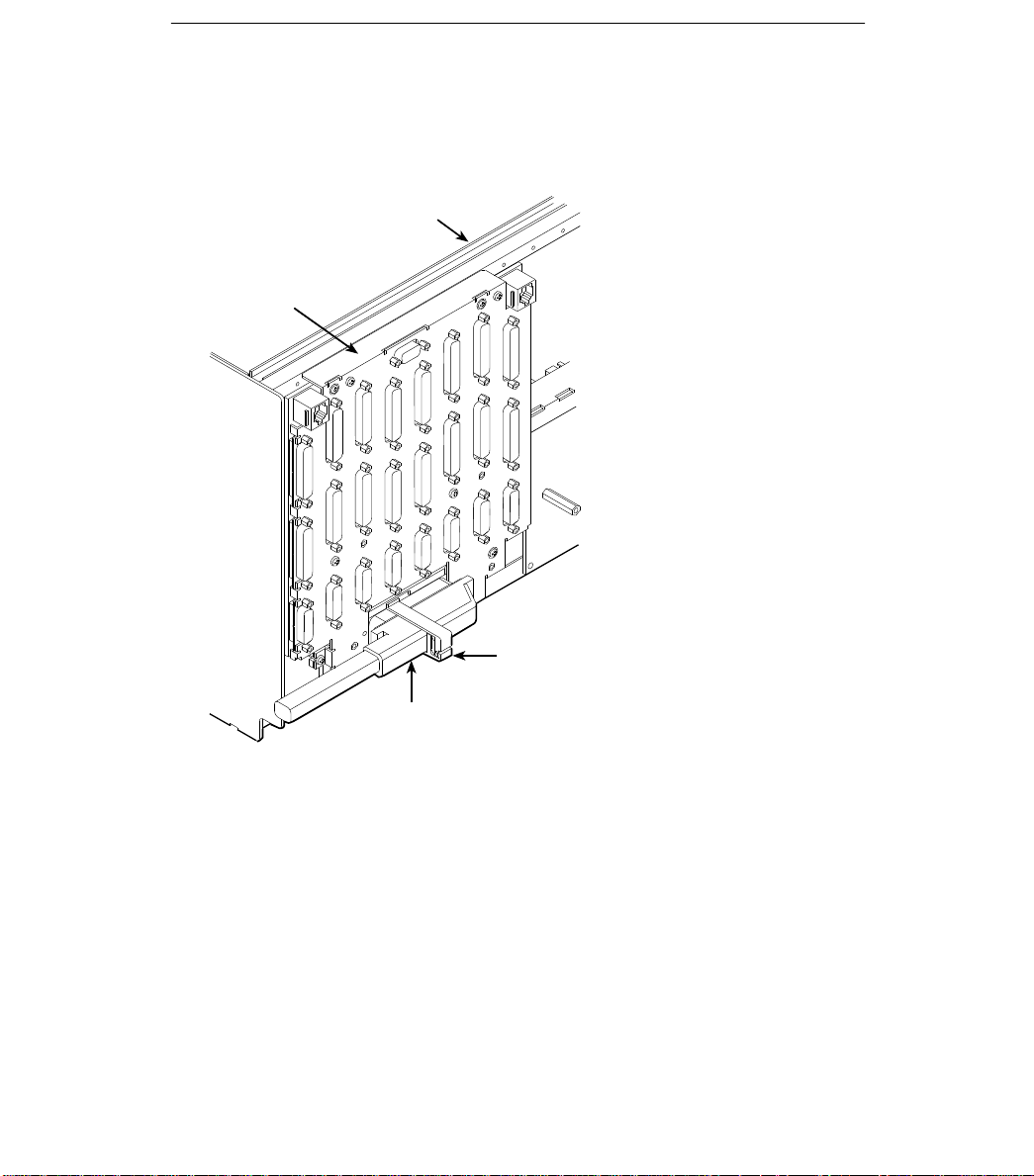
3. Attach the network cable to the Auxiliary Backplane using either a 50-pin cable or
3
the T1 Network Interface Adapter. Connect the other end of the network cable to
the connection provided by the telephone company .
COMSPHERE
3000 Series
Carrier (Rear)
Auxiliary
Backplane
over Slots 9–16
Cable
Retainer
T1 Network
Cable
496-14386-0
4. Turn on the power to the 3000 Series Carrier.
2
Page 5
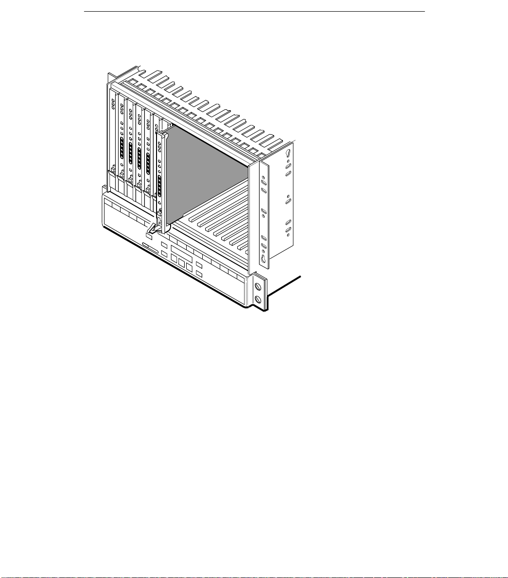
5. Insert the DSU/CSU circuit card into the appropriate slot in the carrier. The
7
power-up self-test begins.
495-1479
6. If you intend to use front panel emulation, connect the cable from the PC to Port 2
on the Auxiliary Backplane using the COM port adapter and COM-port-to-PC cable.
7. If you do not intend to use the DTE Drop/Insert T1 port, disable it using the
configuration procedures in Chapter 3,
Options
Operator’s Guide
, of the
ACCULINK 316x Data Service Unit/Channel Service Unit
(3160-A2-GB21). (The default setting for this port is Enabled.)
Operation
, and Appendix C,
Configuration
8. The Factory 1 configuration for ESF framing format and B8ZS line coding format is
the default configuration and is appropriate for most networks. If this configuration
does not work for you, try the Factory 2 configuration for D4 framing format and
AMI line coding format. To further customize configuration options, refer to
Changing Configuration Options
Configuration Options
Unit Operator’s Guide
, in the
.
in Chapter 3,
Operation
, and Appendix C,
ACCULINK 316x Data Service Unit/Channel Service
9. During the power-up self-test, the FAIL LED flashes, then all LEDs blink twice.
When the test is complete, verify that the DSU/CSU is functional by observing that
the OK, NETWORK SIG, and DTE SIG LEDs are lit.
10. Configure the ports and channels you intend to use and assign channels to the
network interface.
3
Page 6
Configuration Options
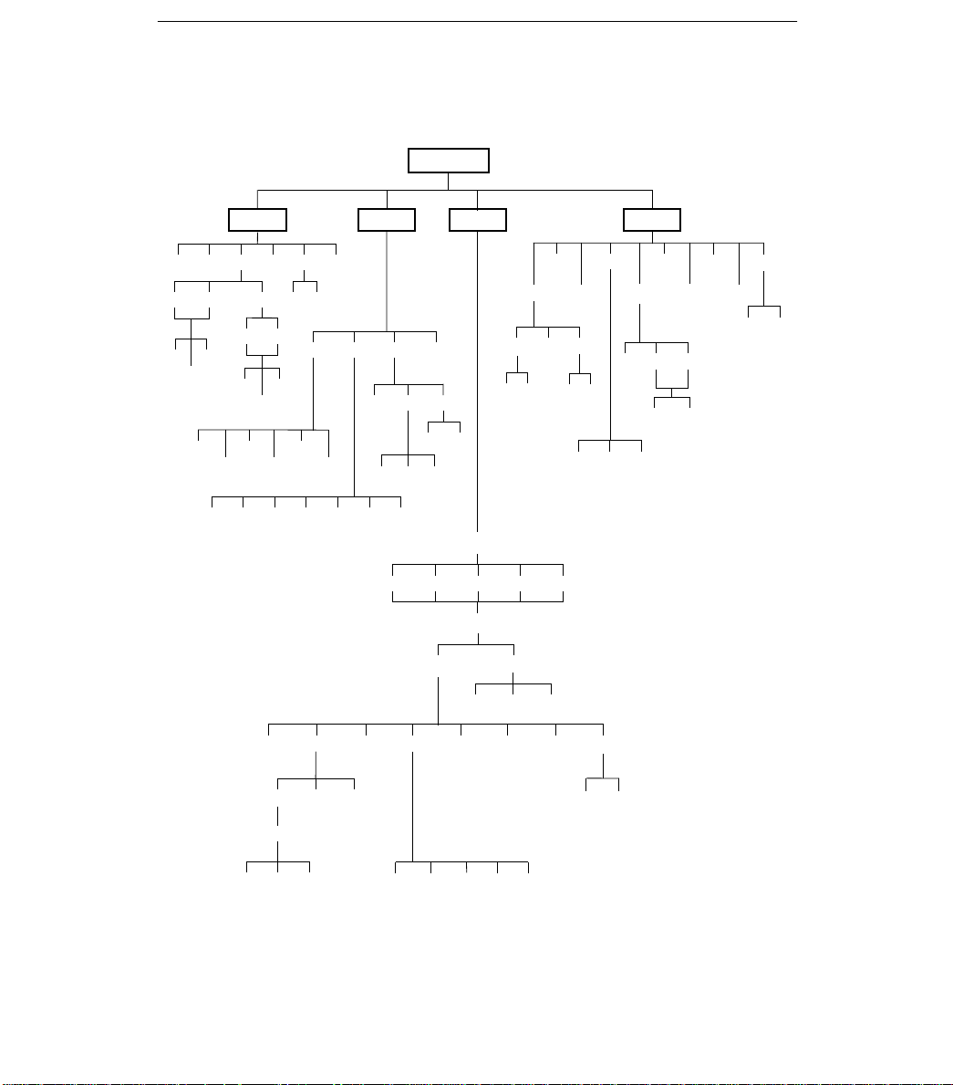
Configuration options are accessed from the Cnfig branch of the front panel menu.
DSU ESF
Stat
DevHS
STest Perf TSt at LED ID
Cur
Intvl
24Tot
LLBUP
Cur
54UP
LLBDN
Test
T1 PrtnPrtnUserTelco
FarNear
Rlpbk Lpbk Ptrns Lamp
Intvl
8Tot
FT1UP
54DN
PLB DLB RLBLLBAbort DCLB DTLB
FT1DN
Abort Mon
QRSS 1in8 511
Cnfig
ACO
Call
DiscDial ChDir
Send
QRSS 511
Load Edit Area From:
Activ Cu st1 Cu st2 Fact1 Fac t2
Choose Function:
Edit
1 . . 5,A
(Directory)
Save
Cust1Activ Cust2
User AlarmNETDTE Port Chan Gen Mgmt
1 . . 5,A
(Directory)
Rel ClrReg
User Prt1 Prt2
DTE Prt1 Prt2
Ctrl
Reset
CID
FarNear
PasswdLED
Mon
DL
EQPT NET
Copy Prt1 Prt2
Port Select :
All Prt1 Pr t2
ClearDsply
DTE Prt 1
4
Prt2
Gen Trap
97-15577
Page 7

Table 1. DTE Interface Configuration Options
Enables the use of the DTE
g
Selects AMI
B8ZS li
(DTE Line
bilit
All
DLB
l
Sel
EIA
Enabl
ith
Network initiated DCLB, allows
5 o ( S) codes
Option Factory 1 Factory 2 Comments/Description
DTE Port:
DTE Framing:
DTE Coding:
Equal:
(DTE Line
Equalizer)
Extrn DLB:
(External DTE
Loopback)
Send Ones:
Enab Enab
Disab Disab
D4 D4
ESF ESF
AMI AMI
B8ZS B8ZS
0–133 0–133
133–266 133–266
266–399 266–399
399–533 399–533
533–655 533–655
Enab Enab
Disab Disab
Enab Enab
Disab Disab
Enables the use of the DTE
Drop/Insert port.
Selects D4 or ESF framing format.
Selects AMI or B8ZS line codin
format.
Provides selectable extended DTE
e ca
range capa
ran
Allows control of DLB on external
ows control of
contact closure.
Sends all ones on channels
allocated to the network T1 on
LOS, LOF, or AIS.
or
abilit
.
y.
ne coding
on externa
Table 2. Port Configuration Options (1 of 3)
Port Type:
Base Rate:
Net DCLB:
Option Factory 1 Factory 2 Comments/Description
E530 E530
V.35 V.35
RS449 RS449
X.21 X.21
Nx64 Nx64
Nx56 Nx56
Disab Disab
V.54 V.54
FT1 FT1
Both Both
5
Selects the
ects the port type:
V.35, RS449, or X.21.
Enables the port to either Nx56 or
Nx64 rates.
Network-initiated DCLB, allows
DCLB to be controlled by inband
V.54 or FT1 (ANSI) codes.
ort t
es the port to e
e: EIA-530A
-530A,
er Nx56 or
Page 8

Table 2. Port Configuration Options (2 of 3)
p,
epo by ee e a
All
(DTE) T1
R
p,
I
Select
All
S
ifi
d
ae)
p
sascs
Option Comments/DescriptionFactory 2Factory 1
Disab Disab
Port LB:
All Ones:
Rcv Yellow:
cv Yellow:
(Received Yellow)
Tx Clock:
InvertTxC:
nvertTxC:
(Invert Tx Clock)
InvertData:
EDL:
DTLB DTLB
DCLB DCLB
Both Both
Disab Disab
DTR DTR
RTS RTS
Both Both
None None
Halt Halt
Int Int
Ext Ext
Enab Enab
Disab Disab
Enab Enab
Disab Disab
Enab Enab
Disab Disab
Port-initiated Loopbacks, allows
Loopbacks to be initiated through
the port by the external DTE.
All ones sent to network (DTE) T1
ones sent to network
when DTR or RTS interrupted.
Data port remains enabled, or is
disabled, on receiving Yellow on
network T1.
Selects whether the transmitted
data clock is internal (TXC) or
external (XTXC).
Selects phase inversion of the
s phase inversion of the
transmit clock (TXC).
Allows the data on the port to be
ows the data on the port to be
inverted.
Specifies whether the Embedded
pec
es whether the Embedde
Data Link is enabled.
Err Rate:
(Excessive Error
Rate)
Near-end:
10E–4 10E–4
10E–5 10E–5
10E–6 10E–6
10E–7 10E–7
10E–8 10E–8
10E–9 10E–9
Disab Disab
Maint Maint
Send Send
Both Both
6
Selects the error rate threshold for
Excessive Error Rate Alarm.
Specifies whether the device will
maintain near-end performance
statistics.
Page 9

Table 2. Port Configuration Options (3 of 3)
p
S
ifi
EDL
Selects AMI or B8ZS line coding
Sends ANSI Performance Report
Specifies whether the FDLs
Network-initiated LLB allows LLB to
Provides enforcement of ones
BitStuff:
62411, ANSI T1-403
FCC
Circuit Ident:
Specifies the transmission vendor s
Option Comments/DescriptionFactory 2Factory 1
Far-end:
Disab Disab
Maint Maint
Enab Enab
Mgmt Link:
Disab Disab
Specifies whether the device will
maintain far-end performance
statistics.
Specifies whether the EDL
pec
es whether the
Management Link is enabled.
Table 3. Network Interface Configuration Options
Option Factory 1 Factory 2 Comments/Description
NET Framing:
NET Coding:
LBO:
ANSI PRM:
Mgmt Link:
NET LLB:
NET PLB:
BitStuff:
Circuit Ident:
D4 D4
ESF ESF
AMI AMI
B8ZS B8ZS
0.0 0.0
–7.5 –7.5
–15 –15
–22.5 –22.5
Enab Enab
Disab Disab
Enab Enab
Disab Disab
Enab Enab
Disab Disab
Enab Enab Network-initiated PLB allows PLB
Disab Disab
62411 62411
Part68 Part68
Disab Disab
Edit Edit
Clear Clear
Selects D4 or ESF framing format.
Selects AMI or B8ZS line coding
format.
Provides Line Build Out in dB.
Sends ANSI Performance Report
Messages.
Specifies whether the FDL’s
Management Link is enabled.
Network-initiated LLB allows LLB to
be controlled by inband LLB codes.
to be controlled by FDL PLB
messages.
Provides enforcement of ones
density protection per AT&T TR
ANSI T1-403
62411
Part 68 Technical Publication.
Specifies the transmission vendor’s
circuit identifier.
and FCC
, and
7
Page 10

Table 4. DTE Drop/Insert Port Channel Configuration Options
N1 N2 N3
N24
(D1, D2
D24
Function key under the channel
Line 1 Displays: Line 2 Displays: Meaning Comments/Description
— Unassigned
N1 N2 N3 ...... N24:
D1 D2 D3 ...... D24:
......
D1, D2 ... D24
:
Prt1
Prt2
Prt3
Prt4
Data Data Channel
RBS
Channel
assigned to this
DTE channel
Channel
assigned to port
1,2,3, or 4
Voice
Channel
Function key under the channel
(N1, N2, etc.) selects the DTE
channel to assign
channel to assi
or –).
Function key under the channel
(D1, D2, etc.) selects either Data
or RBS.
n D1 D2
... D24
, ...
,
8
Page 11

Table 5. Data Port Channel Configuration Options (1 of 2)
Assign T o:
the Network or DSX 1 T1 interface,
Assign By:
assigned: contiguous blocks,
Option Factory 1 Factory 2 Comments/Description
NET NET
Assign T o:
Assign By:
Option Factory 1 Factory 2 Comments/Description
Port Rate:
DTE DTE
Prt
n
Block Block
ACAMI ACAMI
Chan Chan
64 (56)
128 (112)
192 (168)
256 (224)
320 (280)
384 (336)
448 (392)
512 (448)
576 (504)
640 (560)
704 (616)
768 (672)
832 (728)
896 (784)
960 (840)
1024 (896)
1088 (952)
1152 (1008)
1216 (1064)
1280 (1120)
1344 (1176)
1408 (1232)
1472 (1288)
1536 (1344)
128 (112)
192 (168)
256 (224)
320 (280)
384 (336)
448 (392)
512 (448)
576 (504)
640 (560)
704 (616)
768 (672)
832 (728)
896 (784)
960 (840)
1024 (896)
1088 (952)
1152 (1008)
1216 (1064)
1280 (1120)
1344 (1176)
1408 (1232)
1472 (1288)
1536 (1344)
Prt
n
64 (56)
Assigns this port to channels on
the Network or DSX-1 T1 interface,
or to another port.
Determines how channels are
assigned: contiguous blocks,
ACAMI or individual channels.
Selects the data rate for the port.
The possible rates depend on
whether the port is configured for
Nx56 or Nx64.
This configuration option only
appears if the “Assigned By”
configuration option is Block or
ACAMI.
9
Page 12

Table 5. Data Port Channel Configuration Options (2 of 2)
(If assigned to NET)
p
(N1, N2 etc.) assigns (unassigns)
Option Factory 1 Factory 2 Comments/Description
Clear Clear
N1 (D1)
N2 (D2)
N3 (D3)
N4 (D4)
N5 (D5)
N6 (D6)
N7 (D7)
N8 (D8)
N9 (D9)
N10 (D10)
Start At:
Line 1 Displays: Line 2 Displays: Meaning Comments/Description
N1 N2 N3 ...... N24:
(If assigned to NET)
D1 D2 D3 ..... D24:
(If assigned to DTE)
N11 (D11)
N12 (D12)
N13 (D13)
N14 (D14)
N15 (D15)
N16 (D16)
N17 (D17)
N18 (D18)
N19 (D19)
N20 (D20)
N21 (D21)
N22 (D22)
N23 (D23)
N24 (D24)
— Unassigned
Prt1
Prt2
Prt3
Prt4
D1, D2 ... D24
N1, N2 ... N24
N1 (D1)
N2 (D2)
N3 (D3)
N4 (D4)
N5 (D5)
N6 (D6)
N7 (D7)
N8 (D8)
N9 (D9)
N10 (D10)
N11 (D11)
N12 (D12)
N13 (D13)
N14 (D14)
N15 (D15)
N16 (D16)
N17 (D17)
N18 (D18)
N19 (D19)
N20 (D20)
N21 (D21)
N22 (D22)
N23 (D23)
N24 (D24)
Channel
assigned to port 1,
2, 3, or 4
Channel
assigned to this
DTE channel
Channel assigned
to this NET
channel
Clears (unassigns) channels for
this port.
This configuration option appears if
the “Assigned By” configuration
option is Block or ACAMI.
This configuration option appears if
the “Assigned By” configuration
option is individual channels
(Chan).
Function key under the channel
(N1, N2 etc.) assigns (unassigns)
port (1, 2, 3, or 4) to that channel.
10
Page 13

Table 6. General Configuration Options
G
Yell
Clock Src:
used as the master clock for the
Clock Rate:
if
p
Specifies the duration of
es s
Option Factory 1 Factory 2 Comments/Description
Gen Yellow:
en Yellow:
(Generate Yellow)
Clock Src:
Clock Rate:
Enab Enab
Disab Disab
NET NET
DTE DTE
Prt1 Prt1
Int Int
Ext Ext
2048 2048
1544 1544
8 8
Yellow alarm is generated by the
ow alarm is generated by the
DSU/CSU on LOS, LOF, or AIS.
Selects the clock source to be
used as the master clock for the
DSU/CSU.
Selects the clock rate of the source
external.
if external.
Tst Timeout:
T st Duration:
T st Duration:
Enab Enab
Disab Disab
10 10
Up Up
Down Down
Save Save
Specifies whether the durations of
user-initiated tests are limited by
T st Duration.
Specifies the duration of
user-initiated loopback and pattern
tests.
11
Page 14

Table 7. User Configuration Options (1 of 3)
Allows bypass of self-test on
Controls whether dial-in access is
Controls whether a password is
Controls whether the COM port is
devi
Controls the COM ports connect
Controls the COM ports connect
Controls the COM ports escape
Controls the COM ports escape
Controls the COM ports
Option Factory 1 Factory 2 Comments/Description
-
Self-Test:
-
Dial-In:
Password:
Com Port:
Com Use:
ComExtDev:
ComConnPrefix:
ComConnected:
ComEscapeSeq:
ComEscDel:
ComDisconnect:
Enab Enab
Disab Disab
Enab Enab
Disab Disab
None None
Com Com
Enab Enab
Disab Disab
Mgmt Mgmt
ASCII ASCII
Term Term
Disab Disab
AT AT
Other Other
Edit Edit
Clear Clear
Edit Edit
Clear Clear
Edit Edit
Clear Clear
None None
0.2s 0.2s
0.4s 0.4s
0.6s 0.6s
0.8s 0.8s
1.0s 1.0s
Edit Edit
Clear Clear
Allows bypass of self-test on
initialization.
Controls whether dial-in access is
allowed.
Controls whether a password is
required for remote access.
Controls whether the COM port is
enabled or disabled.
Controls how the COM port is
used.
used.
Controls the COM port’s external
device commands.
ce commands.
Controls the COM port’s connect
prefix.
Controls the COM port’s connect
indication string.
Controls the COM port’s escape
sequence.
Controls the COM port’s escape
sequence delay.
Controls the COM port’s
disconnect string.
12
Page 15

Table 7. User Configuration Options (2 of 3)
(Communication Port
Selects the character length for the
(
py p
(Communication Port
the COM
S
ifi
COM
t
p
(COM Port
(1 to 60 minutes) that
TnS
p
TnP
S
ifi
p
Option Comments/DescriptionFactory 2Factory 1
1.2 1.2
2.4 2.4
Com Rate:
(Communication Port
Rate)
Char Length:
CParity:
(Communication Port
Parity)
CStop Bits:
(Communication Port
Stop Bits)
4.8 4.8
9.6 9.6
14.4 14.4
19.2 19.2
38.4 38.4
7 7
8 8
None None
Even Even
Odd Odd
1 1
1.5 1.5
2 2
Selects the bit rate for the COM
ort.
port.
Selects the character length for the
COM port.
Selects the parity for the COM port.
Selects the number of stop bits for
the COM
ort.
port.
Ignore DTR:
CmInActTm:
(COM Port Inactivity
Timeout)
CmDiscTm:
COM Port
Disconnect Time)
TnSession:
(T elnet Session)
TnPaswd:
(T elnet Password)
TnInActTm:
(T elnet Inactivity
Timeout)
ession:
aswd:
Yes Yes
No No
Enab Enab
Disab Disab
5 5
Up Up
Down Down
Save Save
Enab Enab
Disab Disab
Enab Enab
Disab Disab
Enab Enab
Disab Disab
13
Specifies whether the COM port
pec
es whether the
ignores DTR.
Specifies whether the
communication port disconnects
after a certain period of inactivity.
Specifies the period of inactivity
1 to 60 minutes
disconnect if CmInActTm is
enabled.
enabled.
Specifies whether the DSU/CSU
responds to T elnet session
requests.
Specifies whether a password is
pec
es whether a password is
required for T elnet sessions.
Specifies whether a T elnet session
disconnects after a certain period
of inactivity.
that causes a
por
causes a
Page 16

Table 7. User Configuration Options (3 of 3)
(Telnet Di
t
60 minutes) that
p
p
pgg
Rate)
Option Comments/DescriptionFactory 2Factory 1
5 5
TnDiscTm:
T elnet Disconnect
sconnec
Time)
Up Up
Down Down
Save Save
The period of inactivity (1 to
60 minutes
disconnect if TnInActTm is
enabled.
enabled.
Table 8. Alarm Configuration Options (1 of 2)
Option Factory 1 Factory 2 Comments/Description
Disab Disab Does not display alarm messages.
Alrm Msg:
SNMP Trap:
TrapDisc:
DialOut:
Call Retry:
Dial Delay:
AltDialDir:
Err Rate:
(Excessive Error
Rate)
Com Com
Enab Enab
Disab Disab
Enab Enab
Disab Disab
Enab Enab
Disab Disab
Enab Enab
Disab Disab
1–4
5
6–10
None
1–5
10E–4 10E–4
10E–5 10E–5
10E–6 10E–6
10E–7 10E–7
10E–8 10E–8
10E–9 10E–9
1–4
5
6–10
None
1–5
Sends alarm messages to COM
port.
Sends SNMP traps.
Specifies whether the modem
connection will disconnect after a
trap is sent.
Provides the option to allow
automatic dial-out to send alarm
messages on MODEM port.
Specifies whether an outgoing call
is retried on a busy or failed call
attempt.
The time (in minutes) to delay
between successive alarm
dial-outs or retry attempts.
The alternate dial-out directory to
use if a call to the primary number
cannot be completed.
The error rate threshold for
Excessive Error Rate Alarm.
that causes a
causes a
14
Page 17

Table 8. Alarm Configuration Options (2 of 2)
AlrmRelay:
Specifies whether to activate the
p
validates the IP address of an
The number of SNMP managers
y
yp
The SNMP system name for this
The SNMP system location for this
The SNMP system contact name
y
The type of access allowed for
A community name that is allowed
The type of access allowed for
AlrmRelay:
(Alarm Relay)
Table 9. General Management Configuration Options (1 of 2)
SNMP Mgt:
NMS Valid:
Num Sec Mgrs:
NMS n IP Adr:
NMS n Access:
System Name:
System Location:
System Contact:
CommunityName1:
Access 1:
CommunityName2:
Access 2:
Option Comments/DescriptionFactory 2Factory 1
Enab Enab
Disab Disab
Option Factory 1 Factory 2 Comments/Description
Enab Enab
Disab Disab
Enab Enab
Disab Disab
1 1
2–10 2–10
Edit Edit
Clear Clear
Read Read
R/W R/W
Edit Edit
Clear Clear
Edit Edit
Clear Clear
Edit Edit
Clear Clear
Edit Edit
Clear Clear
Read Read
R/W R/W
Edit Edit
Clear Clear
Read Read
R/W R/W
Specifies whether to activate the
alarm relay on an alarm condition.
Specifies whether the DSU/CSU
responds to SNMP session
requests.
Specifies whether the DSU/CSU
validates the IP address of an
SNMP manager attempting
access.
The number of SNMP managers
allowed to access the DSU/CSU.
Allows you to define or clear the
allowable IP address of an SNMP
manager.
The type of access allowed for an
SNMP manager using community
name 1.
The SNMP system name for this
device.
The SNMP system location for this
device.
The SNMP system contact name
for this device.
A community name that is allowed
access to this device. Defaults to
public
.
The type of access allowed for
community name 1.
A community name that is allowed
access to this device.
The type of access allowed for
community name 2.
15
Page 18

Table 9. General Management Configuration Options (2 of 2)
The IP address needed to access
The Subnet Mask needed to
The IP address for the COM port
The link layer protocol for the COM
Specifies whether the device is the
Def Netwk:
destinati
Option Comments/DescriptionFactory 2Factory 1
IP Adr:
NetMask:
Com IP Adr:
Com NetMask:
Com Link:
IPBusMast:
Def Netwk:
Edit Edit
Clear Clear
Edit Edit
Clear Clear
Edit Edit
Clear Clear
Edit Edit
Clear Clear
PPP PPP
SLIP SLIP
Enable Enable
Disab Disab
None None
IPBus IPBus
Com Com
FDL FDL
EDL
n
EDL
n
The IP address needed to access
the device.
The Subnet Mask needed to
access the device.
The IP address for the COM port
when configured for SNMP.
The Subnet Mask needed to
access the device when the COM
port is configured for SNMP.
The link layer protocol for the COM
port when configured for SNMP.
Specifies whether the device is the
IP Bus Master.
Specifies the default network
on.
destination.
16
Page 19

Table 10. Management Trap Configuration Options
trap manager. This configuration
f
pgpyp
Failure or both
p
ppyp
Down, or both
Trap I/F:
,p
Option Factory 1 Factory 2 Comments/Description
Num Trap Mgrs:
Trapn IP Adr:
Trapn Dst:
Gen Trap:
Entp Trap:
Link Trap:
Trap I/F:
1
2–6
Edit Edit
Clear Clear
Def Def
IPBus IPBus
Com Com
FDL FDL
EDL
n
Disab Disab
Warm Warm Specifies the general trap types to
Auth Auth
Both Both
Enab Enab
Disab Disab
Disab Disab
Up Up Specifies the link trap type to
Down Down
Both Both
NET NET
DTE DTE
T1s T1s
Ports Ports
All All
2–6
EDL
1
The number of trap managers
supported by the device.
Specifies the IP address for each
trap manager. This configuration
option is repeated for all
managers.
Specifies the network destination
Mana
or Trap Manager n.
for Tra
n
enable: WarmStart, Authentication
Failure or both.
Specifies whether the
EnterpriseSpecific trap type is
enabled.
enable: Trap on Link Up, Link
Down, or both.
When any link trap types are
enabled, specifies which links to
send traps for.
n
er n.
.
.
17
 Loading...