

Paradyne 3151, 3161, ACCULINK 3151 CSU, ACCULINK 3161 DSU, ACCULINK 3161 CSU Information Manual

ACCULINK® 3151 CSU and 3161 DSU/CSU
General Information Guide
Document Number 3100-A2-GK40-40
July 2000
Introduction
This guide contains general information about the ACCULINK® 3151 Channel
Service Unit (CSU) and the 3161 Data Service Unit/Channel Service Unit
(DSU/CSU). It is designed to be used in conjunction with the
Series Carrier Installation Manual
3151, Operator's Guide
3164-A2, and 3165-A4, Operator's Guide.
The Model 3151 CSU and the Model 3161 DSU/CSU are designed to fit into the
COMSPHERE 3000 Series Carrier.
or the
and the
ACCULINK DSU/CSU, Models 3160-A4, 3161,
Product Documentation Online
COMSPHERE 3000
ACCULINK CSU, Models 3150-A4 and
Complete documentation for this product is available at
Select
Select the following documents:
To request a paper copy of a Paradyne document:
Library → Technical Manuals → T1/E1 Digital Access Devices.
Document No. 3000-A2-GA31
COMSPHERE 3000 Series Carrier Installation Manual
Document No. 3150-A2-GB24
ACCULINK CSU, Models 3150-A4 and 3151, Operator's Guide
Document No. 3160-A2-GB24
ACCULINK DSU/CSU, Models 3160-A4, 3161, 3164-A2, and 3165-A4,
Operator's Guide
Within the U.S.A., call 1-800-PARADYNE (1-800-727-2396)
Outside the U.S.A., call 1-727-53-8623
www.paradyne.com
.
3100-A2-GK40-40 July 2000
1
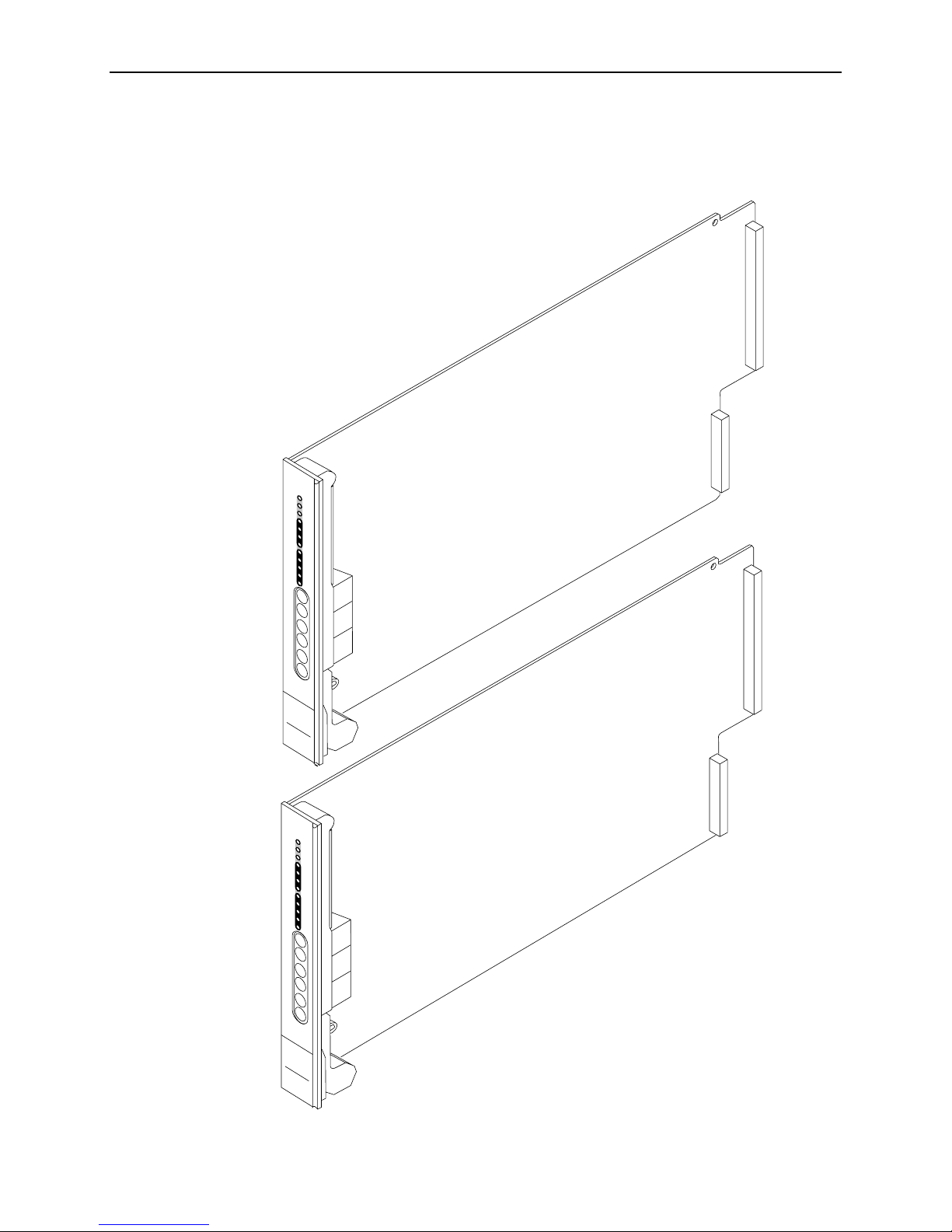
CSU or DSU/CSU Circuit Card
The front panel of the CSU or DSU/CSU contains twelve light-emitting diodes
(LEDs) and six test jacks .
S
e
le
c
t
OK
Fail
Test
Sig
N
e
t
OOF
Alrm
EER
Sig
D
T
OOF
E
Alrm
PDB
BPV
In
N
e
t
O
u
t
In
M
o
n
O
u
t
In
E
q
p
O
u
t
MODEL
3151 CSU
S
D
R
N
M
E
DSU
CSU
3151
e
le
c
t
OK
Fail
Test
Sig
N
e
t
OOF
Alrm
EER
T
R
T
Sig
X
D
X
OOF
D
C
T
Alrm
S
R
T
PDB
S
BPV
In
e
t
O
u
t
In
o
n
O
u
t
In
q
p
O
u
t
/CSU
3161
MODEL
3161
DSU/CSU
00-14949-01
July 2000 3100-A2-GK40-40
2
For information about the CSU or DSU/CSU front panel LEDs, refer to Chapter 3 in
the associated oper ator’s guide
For information about the CSU or DSU/CSU front panel test jacks, refer to
Chapter 8 in the associated operator’s guide
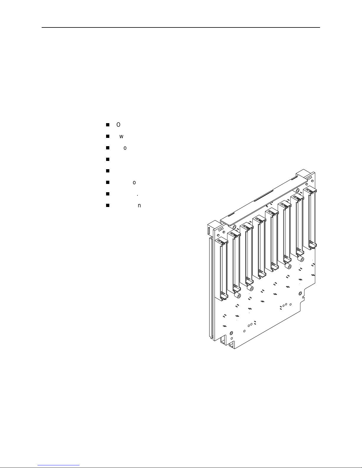
Auxiliary Backplane
Verify that the Auxiliary Backplane package includes the following parts:
One Auxiliary Backplane
Two custom hexagonal standoffs
Two No. 6 nylon insulating washers
Two No. 5 nuts
Four No. 4-40 x 1" screws
Two No. 4-40 x 3/4" screws
One No. 4-40 x 3/8" screw
One T1 network cable retainer
.
.
The Auxiliary Backplane is an 8-slot
backplane that fits over half the open
section of the 3000 Series Carrier. It
is a passive assembly that provides
interconnect capability for the CSUs
or DSU/CSUs.
For more information about the
Auxiliary Backplane and the 3000
Series Carrier, refer to the
COMSPHERE 3000 Series Carrier
Installation Manual
.
493-14387
3100-A2-GK40-40 July 2000
3
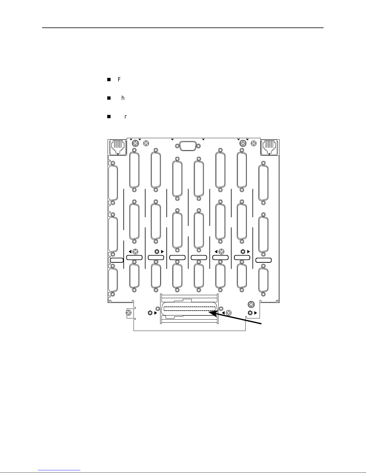
Interface Connections
The Auxiliary Backplane provides the connectors for interface cables.
For information about Auxiliary Backplane connectors, refer to the
COMSPHERE 3000 Series Carrier Installation Manual
The ACCULINK Model 3151 CSU and Model 3161 DSU/CSU are shipped
without cables.
.
For information about cables, refer to the
Installation Manual
DIAGNOSTIC
CHAN
PORT
1
PORT
1
PORT
2
PORT
2
SLOT 7 (15)
SLT 8 (16)
DTE
DTE DTE DTE DTE DTE DTE
SLOT 6 (14)
PORT
1
PORT
2
.
SLOT 5 (13)
PORT
1
PORT
2
SLOT 4 (12) SLOT 3 (11)
CLOCK IN
PORT
1
PORT
2
COMSPHERE 3000 Series Carrier
Top Row of
Screw Holes
DIAGNOSTIC
CHAN
SLOT 2 (10)
PORT
1
PORT
2
SLOT 1 (9)
PORT
1
PORT
2
Center Row of
Screw Holes
DTE
PORT
1
PORT
2
July 2000 3100-A2-GK40-40
4
DISCONNECT ALL TELEPHONE LINES AT THE NETWORK
CAUTION:
INTERFACE BEFORE TOUCHING OR SERVICING
T1 NETWORK
INTERFACE
Bottom Row of
Screw Holes
T1 Network
Interface
Connector
496-14364-01
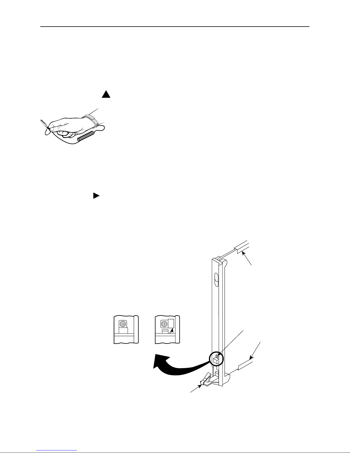
Installing the Circuit Card in a Carrier
Read and follow all warning notices and instructions marked on the device or
included in this guide . See the
HANDLING PRECAUTIONS FOR
!
STATIC-SENSITIVE DEVICES
This product is designed to pro tect sensitive components from damage
due to electrostatic discharge (ESD) during normal operation. When
performing installation procedures, however, take proper static control
precautions to prevent damage to equipment. If you are not sure of the
proper static control precautions, contact your nearest sales or service
representative.
To install a CSU or DSU/CSU circuit card in the 3000 Series Carrier, you must
first install an Auxiliary Backplane. For information about installing the
Auxiliary Backplane, refer to the
Installation Manual
Procedure
To install the circuit card:
.
Important Safety Instructions
on page 12.
COMSPHERE 3000 Series Carrier
1. Use a Phillips screwdriv er to loosen the screw holding the circuit pack lock and
rotate the lock to the open position. Open the latch.
CIRCUIT
CARD
GUIDE
CIRCUIT
PACK
CLOSED
LOCK
OPEN
CIRCUIT
CARD
GUIDE
491-11985a-02
3100-A2-GK40-40 July 2000
LATCH
5
 Loading...