

Paradyne 3150, 3151 Owner's Manual

ACCULINK
315x CHANNEL SERVICE UNIT
OPERATOR’S GUIDE
Document No. 3150-A2-GB21-80
February 1998

ACCULINK 315x CSU
ACCULINK
315x Channel Service Unit
Operator’s Guide
3150-A2-GB21-80
9th Edition (February 1998)
Changes and enhancements to the product and to the information herein will be documented and issued as a new release to
this manual.
Standalone
FCC Registration number: See label on unit
Ringer Equivalence number (REN): See label on unit
Canadian Certification number: See label on unit
Canadian DOC Load number: See label on unit
Carrier Card
FCC Registration number: See label on unit
Ringer Equivalence number (REN): See label on unit
Canadian Certification number: See label on unit
Canadian DOC Load number: See label on unit
Warranty, Sales, and Service Information
Contact your sales or service representative directly for any help needed. For additional information concerning warranty ,
sales, service, repair, installation, documentation, or training, use one of the following methods:
• Via the Internet: Visit the Paradyne World Wide Web site at http://www.paradyne.com
• Via Telephone: Call our automated call system to receive current information via fax or to speak with a company
representative.
— Within the U.S.A., call 1-800-870-2221
— International, call 1-727-530-2340
Trademarks
All products and services mentioned herein are the trademarks, service marks, registered trademarks or registered service
marks of their respective owners.
Printed on recycled paper
COPYRIGHT 1998 Paradyne Corporation. All rights reserved.
This publication is protected by federal copyright law. No part of this publication may be copied or distributed, transmitted, transcribed, stored in a retrieval system,
or translated into any human or computer language in any form or by any means, electronic, mechanical, magnetic, manual or otherwise, or disclosed to third parties
without the express written permission of Paradyne Corporation, 8545 126th Avenue North, P.O. Box 2826, Largo, Florida 33779-2826.
Paradyne Corporation makes no representation or warranties with respect to the contents hereof and specifically disclaims any implied warranties of merchantability
or fitness for a particular purpose. Further, Paradyne Corporation reserves the right to revise this publication and to make changes from time to time in the contents
hereof without obligation of Paradyne Corporation to notify any person of such revision or changes.
A February 1998 3150-A2-GB21-80

Important Safety Instructions
1. Read and follow all warning notices and instructions marked on the product or included in the
manual.
2. This product is intended to be used with a three-wire grounding type plug — a plug which has
a grounding pin. This is a safety feature. Equipment grounding is vital to ensure safe
operation. Do not defeat the purpose of the grounding type plug by modifying the plug or
using an adaptor.
Prior to installation, use an outlet tester or a voltmeter to check the ac receptacle for the
presence of earth ground. If the receptacle is not properly grounded, the installation must not
continue until a qualified electrician has corrected the problem.
If a three-wire grounding type power source is not available, consult a qualified electrician to
determine another method of grounding the equipment.
3. Slots and openings in the cabinet are provided for ventilation. T o ensure reliable operation of
the product and to protect it from overheating, these slots and openings must not be blocked
or covered.
4. Do not allow anything to rest on the power cord and do not locate the product where persons
will walk on the power cord.
Important Instructions
5. Do not attempt to service this product yourself, as opening or removing covers may expose
you to dangerous high voltage points or other risks. Refer all servicing to qualified service
personnel.
6. General purpose cables are provided with this product. Special cables, which may be required
by the regulatory inspection authority for the installation site, are the responsibility of the
customer.
7. When installed in the final configuration, the product must comply with the applicable Safety
Standards and regulatory requirements of the country in which it is installed. If necessary,
consult with the appropriate regulatory agencies and inspection authorities to ensure
compliance.
8. A rare phenomenon can create a voltage potential between the earth grounds of two or more
buildings. If products installed in separate buildings are interconnected, the voltage potential
may cause a hazardous condition. Consult a qualified electrical consultant to determine
whether or not this phenomenon exists and, if necessary, implement corrective action prior to
interconnecting the products.
9. The Model 3150’s input power to the AC voltage configuration of this product must be
provided by a UL Listed or CSA Certified, Class 2 transformer. Input power to the DC
voltage configurations of this product must be provided by a National Electric Code (NEC) or
a Canadian Electric Code (CEC), Part 1, Class 2 circuit.
10. This product contains a coin cell lithium battery that is only to be replaced at the factory.
Caution: There is a danger of explosion if the battery is incorrectly replaced. Replace only
with the same type. Dispose of used batteries according to the battery manufacturer’s
instructions. Attention: Il y a danger d’explosion s’il y a remplacement incorrect de la
batterie. Remplacer uniquement avec une batterie du même type. Mettre au rebut les batteries
usagées conformément aux instructions du fabricant.
B3150-A2-GB21-80 February 1998

ACCULINK 315x CSU
Notices
In addition, if the equipment is to be used with telecommunications circuits, take the following
precautions:
– Never install telephone wiring during a lightning storm.
– Never install telephone jacks in wet locations unless the jack is specifically designed for wet
locations.
– Never touch uninsulated telephone wires or terminals unless the telephone line has been
disconnected at the network interface.
– Use caution when installing or modifying telephone lines.
– Avoid using a telephone (other than a cordless type) during an electrical storm.
There may be a remote risk of electric shock from lightning.
– Do not use the telephone to report a gas leak in the vicinity of the leak.
! ! ! ! !
!
! !!
C February 1998 3150-A2-GB21-80

Government Requirements and Equipment Return
Certain governments require that instructions pertaining to CSU and modem connection to the
telephone network be included in the installation and operation manual. Specific instructions are
listed in the following sections.
United States
NOTICE TO USERS OF THE UNITED STATES TELEPHONE NETWORK
1. This equipment complies with Part 68 of the FCC rules. On the equipment is a label that
contains, among other information, the FCC registration number and ringer equivalence
number (REN) for this equipment. The label is located on the bottom of the 3150 CSU, and
on the 3151 CSU’s circuit card. If requested, this information must be provided to the
telephone company.
2. There are two types of telephone lines associated with the standalone equipment. The T1
network connection should be made using a Universal Service Order Code (USOC) type
RJ48C jack. The Service Order Code 6.0F should be specified to the telephone company
when ordering the T1 line. In addition, the proper Facility Interface Code must be specified
to the T elephone Company. The CSU can be configured to support any of the following
framing format and line signaling techniques. The CSU’s configuration must correspond to
the T1 line’s parameters. The 3150 CSU’s internal modem connects to the Public Switched
T elephone Network using a USOC Type RJ11C jack. The Facility Interface Code 02LS2
along with the RJ11C jack should be specified to the telephone company when ordering a
dial line for the modem. The 3151 CSU connects to the T1 network using the multi-line
USOC-type RJ48H jack and does not have a PSTN interface.
Government Requirements
315x CSU Facility Interface Codes
Code
04DU9-BN 1.544 Mbps superframe format (SF) without line power
04DU9-DN 1.544 Mbps SF and B8ZS without line power
04DU9-1KN 1.544 Mbps ANSI ESF without line power
04DU-1SN 1.544 Mbps ANSI ESF and B8ZS without line power
Description
3. The ringer equivalence number (REN) is used to determine the quantity of devices which
may be connected to the telephone line. Excessive RENs on the telephone line may result
in the devices not ringing in response to an incoming call. In most, but not all areas, the
sum of the RENs should not exceed five (5.0). T o be certain of the number of devices that
may be connected to the line, as determined by the total RENs, contact the telephone
company to determine the maximum RENs for the calling area.
D3150-A2-GB21-80 February 1998

ACCULINK 315x Channel Service Unit
4. If the 315x CSU causes harm to the telephone network, the telephone company will notify
you in advance that temporary discontinuance of service may be required. But if advance
notice is not practical, the telephone company will notify the customer as soon as possible.
Also, you will be advised of your right to file a complaint with the FCC if you believe it is
necessary.
5. The telephone company may make changes in its facilities, equipment, operations, or
procedures that could affect the operation of the equipment. If this happens, the telephone
company will provide advance notice in order for you to make the necessary modifications
in order to maintain uninterrupted service.
6. If you experience trouble with this equipment, please contact your sales or service
representative (as appropriate) for repair or warranty information. If the product needs to
be returned to the company service center for repair, contact them directly for return
instructions using one of the following methods:
• Via the Internet: Visit the Paradyne World Wide Web site at http://www.paradyne.com
• Via Telephone: Call our automated call system to receive current information via fax or
to speak with a company representative.
— Within the U.S.A., call 1-800-870-2221
— Outside the U.S.A., call 1-727-530-2340
If the trouble is causing harm to the telephone network, the telephone company may
request that you remove the equipment from the network until the problem is resolved.
7. The equipment’s modem cannot be used on public coin service provided by the telephone
company . Connection to Party Line Service is subject to state tariffs. (Contact the state
public utility commission, public service commission or corporation commission for
information.)
8. FCC compliant telephone line cords with modular plugs are provided with this equipment.
This equipment is designed to be connected to the telephone network or premises wiring
using a compatible modular jack which is Part 68 compliant.
Canada
NOTICE TO USERS OF THE CANADIAN TELEPHONE NETWORK
The Canadian Department of Communications label identifies certified equipment. This
certification means that the equipment meets certain telecommunications network protective,
operational and safety requirements. The Department does not guarantee the equipment will
operate to the user’s satisfaction.
Before installing this equipment, users should ensure that it is permissible to be connected to the
facilities of the local telecommunications company. The equipment must also be installed using an
acceptable method of connection. In some cases, the company’s inside wiring associated with a
single line individual service may be extended by means of a certified connector assembly
(telephone extension cord). The customer should be aware that compliance with the above
conditions may not prevent degradation of service in some situations.
E February 1998 3150-A2-GB21-80

Government Requirements
Repairs to certified equipment should be made by an authorized Canadian maintenance facility
designated by the supplier. Any repairs or alterations made by the user to this equipment, or
equipment malfunctions, may give the telecommunications company cause to request to disconnect
the equipment.
CAUTION
Users should not attempt to make such connections themselves, but
should contact the appropriate electric inspection authority, or
electrician, as appropriate.
If your equipment is in need of repair, return it using the procedures described on page A in the
front of this document.
F3150-A2-GB21-80 February 1998

Table of Contents
Preface
Objectives and Reader Assumptions iii. . . . . . . . . . . . . . . . . . . . . . . . . . .
Related Documents iii. . . . . . . . . . . . . . . . . . . . . . . . . . . . . . . . . . . . . . . .
Reference Documents iii. . . . . . . . . . . . . . . . . . . . . . . . . . . . . . . . . . . . . .
1. Introduction
Overview 1-1. . . . . . . . . . . . . . . . . . . . . . . . . . . . . . . . . . . . . . . . . . . . . . . .
Features 1-1. . . . . . . . . . . . . . . . . . . . . . . . . . . . . . . . . . . . . . . . . . . . . . . . .
Physical Description 1-3. . . . . . . . . . . . . . . . . . . . . . . . . . . . . . . . . . . . . . .
2. Installation
Overview 2-1. . . . . . . . . . . . . . . . . . . . . . . . . . . . . . . . . . . . . . . . . . . . . . . .
Application Example 2-1. . . . . . . . . . . . . . . . . . . . . . . . . . . . . . . . . . . . . . .
SNMP or T elnet Connection Examples 2-2. . . . . . . . . . . . . . . . . . . . . . . . .
Important Instructions 2-4. . . . . . . . . . . . . . . . . . . . . . . . . . . . . . . . . . . . . .
Optional Power Sources 2-4. . . . . . . . . . . . . . . . . . . . . . . . . . . . . . . . . . . . .
Cabling Examples 2-7. . . . . . . . . . . . . . . . . . . . . . . . . . . . . . . . . . . . . . . . .
Power-Up Self-Test 2-8. . . . . . . . . . . . . . . . . . . . . . . . . . . . . . . . . . . . . . . .
3. Operation
Overview 3-2. . . . . . . . . . . . . . . . . . . . . . . . . . . . . . . . . . . . . . . . . . . . . . . .
Using the Front Panel 3-2. . . . . . . . . . . . . . . . . . . . . . . . . . . . . . . . . . . . . . .
Displaying Unit Identity 3-7. . . . . . . . . . . . . . . . . . . . . . . . . . . . . . . . . . . .
Setting Customer Identification 3-8. . . . . . . . . . . . . . . . . . . . . . . . . . . . . . .
Displaying LED Conditions 3-8. . . . . . . . . . . . . . . . . . . . . . . . . . . . . . . . . .
Changing Configuration Options 3-9. . . . . . . . . . . . . . . . . . . . . . . . . . . . . .
Configuring the CSU for SNMP or T elnet Access 3-11. . . . . . . . . . . . . . . .
Configuring SNMP Traps 3-16. . . . . . . . . . . . . . . . . . . . . . . . . . . . . . . . . . .
Establishing Access Security on a Port 3-18. . . . . . . . . . . . . . . . . . . . . . . . .
Setting a Password 3-18. . . . . . . . . . . . . . . . . . . . . . . . . . . . . . . . . . . . . . . . .
Entering a Password to Gain Access 3-19. . . . . . . . . . . . . . . . . . . . . . . . . . .
Acquiring/Releasing the User Interface 3-19. . . . . . . . . . . . . . . . . . . . . . . . .
Enabling/Disabling the Front Panel 3-20. . . . . . . . . . . . . . . . . . . . . . . . . . . .
Using the Integral Modem in Standalone CSUs 3-21. . . . . . . . . . . . . . . . . .
Enabling the Communication Port for Carrier-Mounted CSUs 3-25. . . . . . .
Deactivating the Alarm Relay for Carrier-Mounted CSUs 3-27. . . . . . . . . .
Resetting the CSU 3-27. . . . . . . . . . . . . . . . . . . . . . . . . . . . . . . . . . . . . . . . .
Download Operations 3-27. . . . . . . . . . . . . . . . . . . . . . . . . . . . . . . . . . . . . .
i3150-A2-GB21-80 February 1998

ACCULINK 315x CSU
4. Maintenance
Overview 4-1. . . . . . . . . . . . . . . . . . . . . . . . . . . . . . . . . . . . . . . . . . . . . . . .
Self-Test Health 4-2. . . . . . . . . . . . . . . . . . . . . . . . . . . . . . . . . . . . . . . . . . .
Device Health and Status 4-3. . . . . . . . . . . . . . . . . . . . . . . . . . . . . . . . . . . .
Performance Reports 4-4. . . . . . . . . . . . . . . . . . . . . . . . . . . . . . . . . . . . . . .
Alarms 4-8. . . . . . . . . . . . . . . . . . . . . . . . . . . . . . . . . . . . . . . . . . . . . . . . . .
SNMP Traps 4-9. . . . . . . . . . . . . . . . . . . . . . . . . . . . . . . . . . . . . . . . . . . . . .
Troubleshooting 4-10. . . . . . . . . . . . . . . . . . . . . . . . . . . . . . . . . . . . . . . . . . .
T est Jacks 4-12. . . . . . . . . . . . . . . . . . . . . . . . . . . . . . . . . . . . . . . . . . . . . . . .
T est Commands 4-14. . . . . . . . . . . . . . . . . . . . . . . . . . . . . . . . . . . . . . . . . . .
Remote Loopback T ests 4-14. . . . . . . . . . . . . . . . . . . . . . . . . . . . . . . . . . . . .
Local Loopback T ests 4-15. . . . . . . . . . . . . . . . . . . . . . . . . . . . . . . . . . . . . .
T est Patterns 4-18. . . . . . . . . . . . . . . . . . . . . . . . . . . . . . . . . . . . . . . . . . . . . .
Lamp T est 4-19. . . . . . . . . . . . . . . . . . . . . . . . . . . . . . . . . . . . . . . . . . . . . . . .
Displaying CSU T est Status 4-21. . . . . . . . . . . . . . . . . . . . . . . . . . . . . . . . . .
Appendices
A. Front Panel Menu A-1. . . . . . . . . . . . . . . . . . . . . . . . . . . . . . . . . . . . . .
B. Technical Specifications B-1. . . . . . . . . . . . . . . . . . . . . . . . . . . . . . . .
C. Configuration Options C-1. . . . . . . . . . . . . . . . . . . . . . . . . . . . . . . . . .
D. Pin Assignments D-1. . . . . . . . . . . . . . . . . . . . . . . . . . . . . . . . . . . . . . .
E. SNMP MIB Objects E-1. . . . . . . . . . . . . . . . . . . . . . . . . . . . . . . . . . . .
F. IP Network Addressing Scenarios F-1. . . . . . . . . . . . . . . . . . . . . . . . .
G. Front Panel Emulation G-1. . . . . . . . . . . . . . . . . . . . . . . . . . . . . . . . . .
H. Async T erminal Operation H-1. . . . . . . . . . . . . . . . . . . . . . . . . . . . . . .
I. Equipment List I-1. . . . . . . . . . . . . . . . . . . . . . . . . . . . . . . . . . . . . . . .
Glossary
Index
ii February 1998 3150-A2-GB21-80

Preface
Objectives and Reader
Assumptions
This operator’s guide contains installation, operation,
and maintenance information for the ACCULINK 315x
Channel Service Unit (CSU).
It is assumed that you are familiar with the operation of
digital data communications equipment. You should also
be familiar with Simple Network Management Protocol
(SNMP) if you want your CSU to be managed by an
SNMP manager.
Related Documents
3000-A2-GA31 COMSPHERE 3000 Series
Carrier Installation Manual
3000-A2-GB41 COMSPHERE –48 VDC
Central Office Power Unit
Installation Guide
3100-A2-GK40 ACCULINK 3151 CSU and
3161 DSU/CSU General
Information Guide
Reference Documents
• AT&T Technical Reference 54016
• AT&T Technical Reference 62411
• ANSI T1.403-1989
• Industry Canada CS-03
• CSA-22.2 No. 950
• Industry Canada (ICES)-003
• FCC Part 15
• FCC Part 68
• UL 1950
• Management Information Base for Network
Management of TCP/IP-Based Internets: MIBII.
RFC 1213, March 1991
• Definitions of Managed Objects for the DS1 and E1
Interface T ypes . RFC 1406, January 1993
• Definitions of Managed Objects for RS-232-like
Hardware Devices. RFC 1317, April 1992
• Extensions to the Generic-Interface MIB.
RFC 1229, May 1991
iii3150-A2-GB21-80 February 1998

Introduction
Overview 1-1. . . . . . . . . . . . . . . . . . . . . . . . . . . . . . . . . . . . . . . . . . . . . . . . . . . . . . . . . . . . . . . . . . . . . . . . . .
Features 1-1. . . . . . . . . . . . . . . . . . . . . . . . . . . . . . . . . . . . . . . . . . . . . . . . . . . . . . . . . . . . . . . . . . . . . . . . . . .
Alarm Message Capability 1-2. . . . . . . . . . . . . . . . . . . . . . . . . . . . . . . . . . . . . . . . . . . . . . . . . . . . . . . . .
Front Panel Emulation 1-2. . . . . . . . . . . . . . . . . . . . . . . . . . . . . . . . . . . . . . . . . . . . . . . . . . . . . . . . . . . . .
Integral Modem 1-2. . . . . . . . . . . . . . . . . . . . . . . . . . . . . . . . . . . . . . . . . . . . . . . . . . . . . . . . . . . . . . . . . .
Async Terminal Interface Support 1-2. . . . . . . . . . . . . . . . . . . . . . . . . . . . . . . . . . . . . . . . . . . . . . . . . . . .
Telnet Access 1-2. . . . . . . . . . . . . . . . . . . . . . . . . . . . . . . . . . . . . . . . . . . . . . . . . . . . . . . . . . . . . . . . . . . .
SNMP Management Support 1-2. . . . . . . . . . . . . . . . . . . . . . . . . . . . . . . . . . . . . . . . . . . . . . . . . . . . . . . .
Physical Description 1-3. . . . . . . . . . . . . . . . . . . . . . . . . . . . . . . . . . . . . . . . . . . . . . . . . . . . . . . . . . . . . . . . .
Standalone CSU Front Panel 1-3. . . . . . . . . . . . . . . . . . . . . . . . . . . . . . . . . . . . . . . . . . . . . . . . . . . . . . . .
Standalone CSU Rear Panel 1-4. . . . . . . . . . . . . . . . . . . . . . . . . . . . . . . . . . . . . . . . . . . . . . . . . . . . . . . .
1
Overview
The CSU acts as an interface between the T1 digital
network and the customer premises equipment, converting
signals received from the DTE (Data T erminal
Equipment) to bipolar signals that can be transmitted over
T1 lines.
The Model 3150 is a standalone CSU, and the
Model 3151 is a carrier-mounted CSU that is designed to
fit into the COMSPHERE 3000 Series Carrier.
For more information about the carrier-mounted CSU,
refer to the ACCULINK 3151 CSU and 3161 DSU/CSU
General Information Guide and the COMSPHERE 3000
Series Carrier Installation Manual.
Features
The CSU optimizes network performance with a wide
range of features such as the following:
• Software configuration menu displayed via a liquid
crystal display (LCD) to permit quick and easy
operation, and elimination of complicated hardware
strapping.
• Local or remote configuration and operation
flexibility .
• Several loopback capabilities and test pattern
generators.
• Alarm message display/print capability .
• Front panel emulation via Windows-based Front
Panel Emulation software.
• Integral modem for standalone CSUs.
• Asynchronous (async) terminal interface support.
• T elnet access for remote async terminal operations.
• Network management provided through
industry-standard Simple Network Management
Protocol (SNMP).
1-13150-A2-GB21-80 February 1998

ACCULINK 315x CSU
Alarm Message Capability
The CSU can be attached, either locally or remotely, to
an ASCII terminal or printer to display or print alarm
messages. Alarms can also be displayed on a PC that is
using a terminal emulation package.
Front Panel Emulation
The CSU offers functionality through Front Panel
Emulation software that is similar to that provided by the
CSU front panel. The functionality of the front panel is
available by clicking on the function keys with the mouse
rather than by pressing keys from the actual front panel.
Integral Modem
The standalone CSUs contain an integral low-speed
(2400 bps), V.22bis dial modem that enables
communication with remote devices such as another 3150
CSU, an ASCII terminal or printer, or a PC running the
3100 Series Front Panel Emulation software.
Async Terminal Interface Support
The DSU/CSU can be configured and managed from
an asynchronous (async) terminal. The async terminal’s
full screen display uses a menu hierarchy similar to the
DSU/CSU’s front panel. You can perform device
management and configuration operations as if you are
using the DSU/CSU’ s front panel, but you do not have the
limitation of the 2-line, 16-character LCD.
Telnet Access
Remote async terminal operations can be performed
using T elnet access. Telnet is a Transmission Control
Protocol/Internet Protocol (TCP/IP) service that supports
a virtual terminal interface.
SNMP Management Support
SNMP is a network management protocol that is used
to monitor network performance and status, and to report
alarms (i.e., traps). T o function, SNMP requires a manager
consisting of a software program housed within a
workstation or PC; an agent consisting of a software
program housed within a device (e.g., the CSU); and a
Management Information Base (MIB) consisting of a
database of managed objects. The CSU can be managed
by any industry-standard SNMP manager.
T wo link layer protocols, Point-to-Point Protocol (PPP)
and Serial Line Internet Protocol (SLIP), are supported for
connection to an external SNMP manager or network
device (e.g., a router).
The SNMP manager or network device can be directly
connected to the communications (COM) port. An
external LAN Adapter can be connected to either the
COM port or the auxiliary (AUX) port to provide Ethernet
connectivity. Also, the CSU can be daisy chained together
by connecting the COM port of one device to the AUX
port of the other, providing SNMP connectivity.
The SNMP management system can communicate to
the CSU remotely through the Facility Data Link (FDL).
1-2 February 1998 3150-A2-GB21-80
Chapter Title
8
Physical Description
The 315x Series consists of a Model 3150 (standalone)
CSU and a Model 3151 (carrier-mounted) CSU.
For more information about the carrier-mounted CSU,
refer to the ACCULINK 3151 CSU and 3161 DSU/CSU
General Information Guide and the COMSPHERE 3000
Series Carrier Installation Manual.
ACCULINK
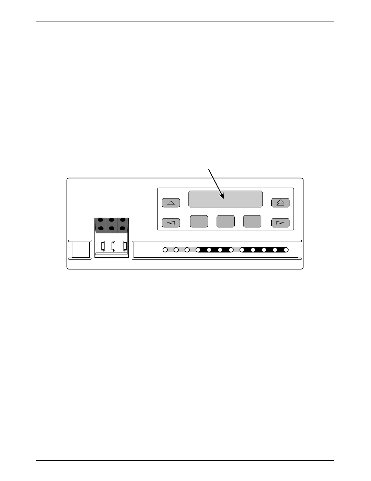
Standalone CSU Front Panel
The standalone CSU front panel contains,
• One 2-line, 16-alphanumeric-character-per-line
liquid crystal display (LCD)
• One 7-button keypad (three Function and four
directional keys)
• T welve light-emitting diodes (LEDs)
• Six test jacks
The front panel is shown in Figure 1-1.
LCD
F1 F2 F3
3150
NET MON EQPT
In
OutInOutInOut
OK
FAIL TEST SIG OOF ALRM
NETWORK
EER SIG ALRM PDVOOF BPV
Figure 1-1. 3150 CSU Front Panel
DTE
496-1493
1-33150-A2-GB21-80 February 1998
ACCULINK 315x CSU
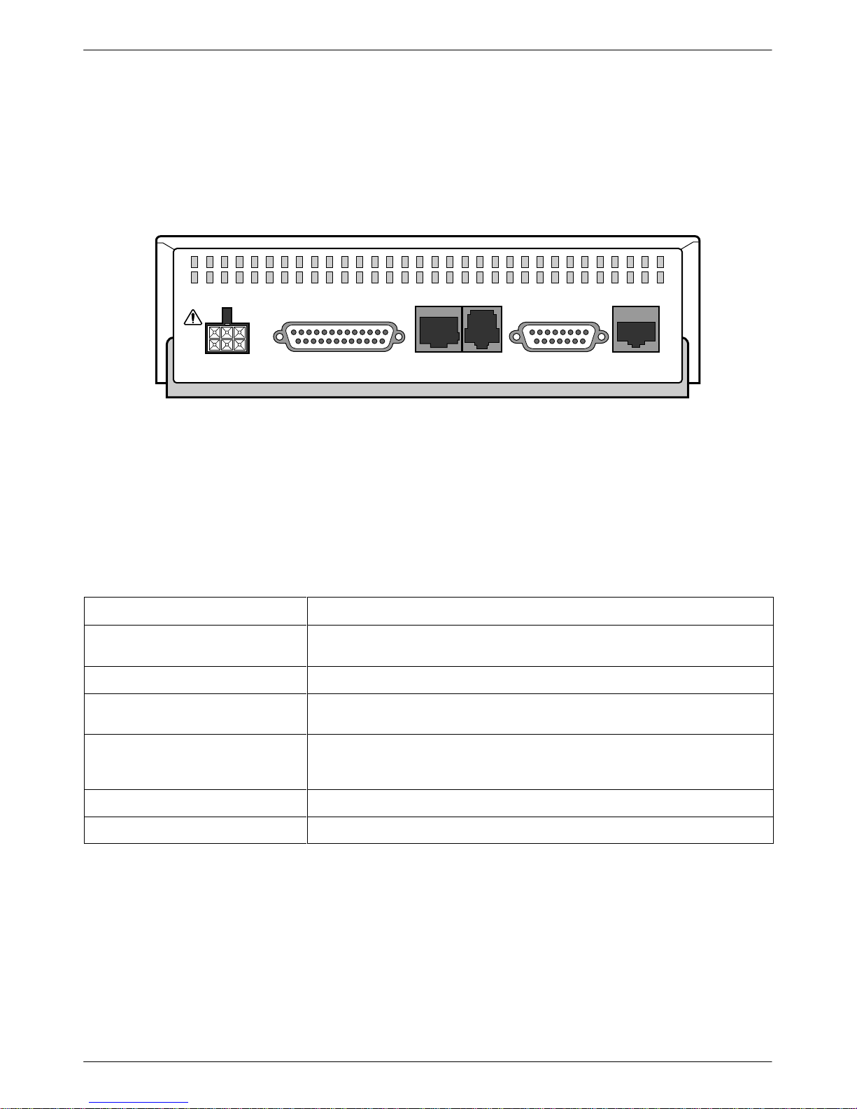
Standalone CSU Rear Panel
The standalone CSU rear panel contains the connectors
required for the operation of the CSU (Figure 1-2). The
connectors and their functions are listed in Table 1-1.
POWER
NEC
CLASS 2
INPUT
AUX PORT
CAUTION:
COM PORT MODEM
DTE
AUX PORT OR COM PORT MUST NOT BE CONNECTED TO PSTN OR T1 NETWORK
NETWORK
494-14538
Figure 1-2. 3150 CSU Rear Panel
Table 1-1
Standalone CSU Rear Panel Connectors
Name
POWER Supplies power to the CSU by providing an attachment for the ac power module
or the optional dc power cable (+24 or –48 Vdc).
AUX PORT Supports SNMP LAN Adapter or daisy-chain connections.
Function
COM PORT Provides access to a locally connected PC, ASCII terminal or printer, SNMP
MODEM Provides a connection to the integral modem for access to a remotely connected
NETWORK Provides access to the T1 network.
DTE Provides access to the T1 DTE interface.
1-4 February 1998 3150-A2-GB21-80
management link, or async terminal interface.
PC, ASCII terminal or printer, SNMP management link, or async terminal
interface.
Installation
Overview 2-1. . . . . . . . . . . . . . . . . . . . . . . . . . . . . . . . . . . . . . . . . . . . . . . . . . . . . . . . . . . . . . . . . . . . . . . . . .
Application Example 2-1. . . . . . . . . . . . . . . . . . . . . . . . . . . . . . . . . . . . . . . . . . . . . . . . . . . . . . . . . . . . . . . .
SNMP or Telnet Connection Examples 2-2. . . . . . . . . . . . . . . . . . . . . . . . . . . . . . . . . . . . . . . . . . . . . . . . . .
Important Instructions 2-4. . . . . . . . . . . . . . . . . . . . . . . . . . . . . . . . . . . . . . . . . . . . . . . . . . . . . . . . . . . . . . . .
Optional Power Sources 2-4. . . . . . . . . . . . . . . . . . . . . . . . . . . . . . . . . . . . . . . . . . . . . . . . . . . . . . . . . . . . . .
Installing the +24 Vdc Power Supply 2-4. . . . . . . . . . . . . . . . . . . . . . . . . . . . . . . . . . . . . . . . . . . . . . . . .
Installing the Single –48 Vdc Power Supply 2-5. . . . . . . . . . . . . . . . . . . . . . . . . . . . . . . . . . . . . . . . . . . .
Installing the Redundant –48 Vdc Power Supply 2-6. . . . . . . . . . . . . . . . . . . . . . . . . . . . . . . . . . . . . . . .
Cabling Examples 2-7. . . . . . . . . . . . . . . . . . . . . . . . . . . . . . . . . . . . . . . . . . . . . . . . . . . . . . . . . . . . . . . . . . .
Power-Up Self-Test 2-8. . . . . . . . . . . . . . . . . . . . . . . . . . . . . . . . . . . . . . . . . . . . . . . . . . . . . . . . . . . . . . . . . .
2
Overview
This chapter contains information for installing your
standalone CSU. It includes application examples,
cabling, and power-up information.
NOTE
Installation instructions for the
carrier-mounted CSU are located
in the
ACCULINK 3151 CSU and
3161 DSU/CSU General
Information Guide
COMSPHERE 3000 Series
Carrier Installation Manual
and the
.
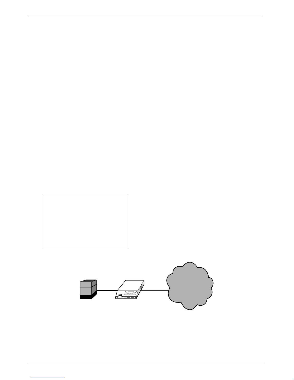
Application Example
The CSU acts as an interface between the T1 digital
network and the customer’s equipment. Figure 2-1 shows
an example of a CSU application.
The CSU is connected to the customer’s equipment
through the T1 DTE interface. It is connected to the T1
digital network through the network interface.
NETWORK
PBX
CSU
496-14821-02
Figure 2-1. Application Example
2-13150-A2-GB21-80 February 1998
ACCULINK 315x CSU
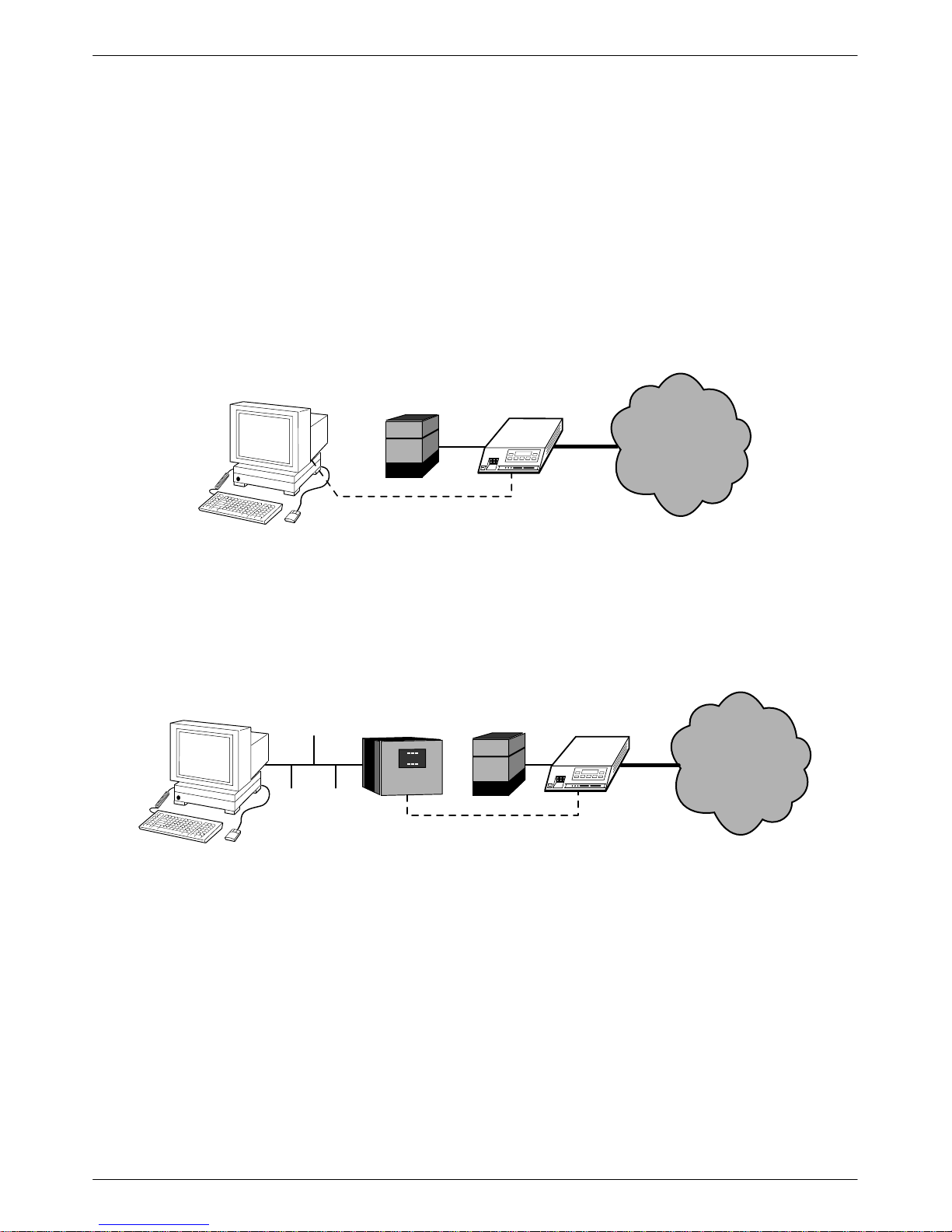
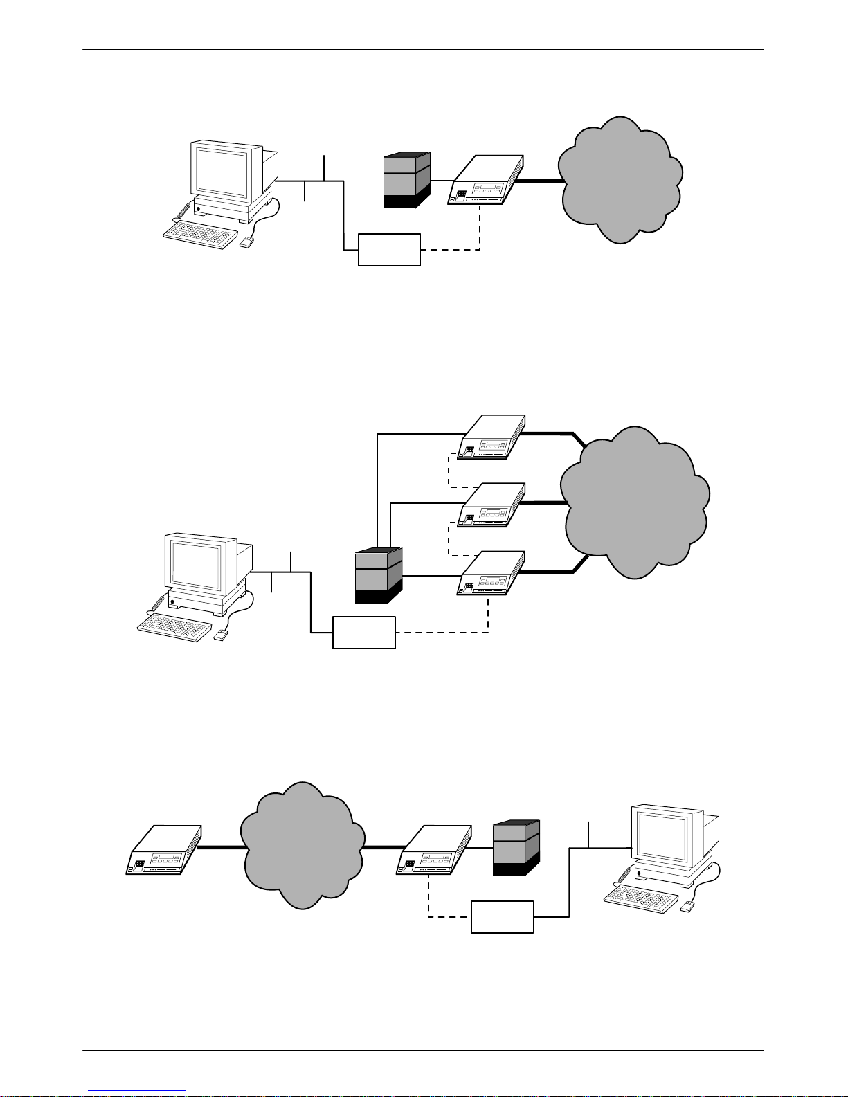
SNMP or Telnet Connection
Examples
The CSU can be connected to an SNMP or T elnet
system in a number of ways. Some examples include:
• Directly connecting the COM port to the SNMP or
T elnet device (Figure 2-2).
• Connecting the COM port to a network device (e.g.,
a router) (Figure 2-3).
PBX
PPP/SLIP
Figure 2-2. Direct Connection
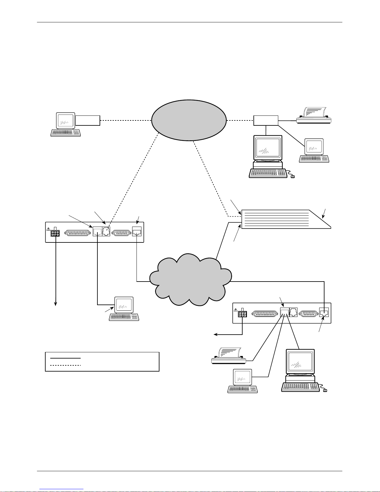
• Connecting the COM port or the AUX port to an
external LAN Adapter for Ethernet connectivity
(Figure 2-4).
• Daisy chaining the COM port of one device to the
AUX port of the other (Figure 2-5).
• Remotely accessing the CSU through the Facility
Data Link (FDL) (Figure 2-6).
CSU
NETWORK
496-14822-02
ETHERNET
LAN
ROUTER
PPP/SLIP
Figure 2-3. Connection through a Router
CSUPBX
NETWORK
496-14823-02
2-2 February 1998 3150-A2-GB21-80
Installation
2
ETHERNET
PBX
PBX
LAN
ADAPTER
PPP
CSU
Figure 2-4. Connection through a LAN Adapter
CSU
ETHERNET
PBX
PPP
PPP
CSU
CSU
NETWORK
496-14824-02
NETWORK
FDL
LAN
ADAPTER
PPP
Figure 2-5. LAN Adapter and Daisy Chaining
CSUCSU
PBX
NETWORK
PPP
LAN
ADAPTER
Figure 2-6. Remote Access through FDL
496-14825-02
ETHERNET
496-14826-0
2-33150-A2-GB21-80 February 1998

ACCULINK 315x CSU
1
Important Instructions
Read and follow all warning notices and instructions
marked on the CSU or included in this guide.
For a complete listing of the safety instructions, see the
Important Safety Instructions section at the beginning of
this guide.
HANDLING PRECAUTIONS
FOR
ST ATIC-SENSITIVE DEVICES
This product is designed to protect
sensitive components from damage
due to electrostatic discharge (ESD)
during normal operation. When
performing installation procedures,
however, take proper static control
precautions to prevent damage to
equipment. If you are not sure of the
proper static control precautions,
contact your nearest sales or service
representative.
Optional Power Sources
The CSU is typically powered by the ac power
module. Use the following procedures only if you want
to use an optional dc power source.
Using the optional dc power cable, the CSU is capable
of operating on either a +24 Vdc power source, –48 Vdc
single source battery, or –48 Vdc redundant source
batteries (for power backup). T o use dc power, choose one
of the following power supply types.
Installing the +24 Vdc Power Supply
T o install the CSU using a +24 Vdc power supply, refer
to Figure 2-7 and use the following procedure.
T o install the +24 Vdc power supply,
1. Connect the green wire to a suitable earth ground.
2. Connect the white wire to the +24 Vdc return.
3. Connect the orange wire to the +24 Vdc source.
DSU/CSU POWER
PLUG
1
2
3
4
5
6
Figure 2-7. +24 Vdc Power Supply Pinouts
BLACK
RED
GREEN
WHITE
ORANGE
BLUE
4. Cut the black, red, and blue wires off at the outer
insulation.
5. Plug the power connector into the CSU.
TO CUSTOMER-SUPPLIED BATTERY
X
X
EARTH GROUND
+24 VDC RETURN
+24 VDC SOURCE
X
496-14298-0
2-4 February 1998 3150-A2-GB21-80

Installation
1
Installing the Single –48 Vdc Power Supply
T o install the CSU using a single source –48 Vdc
power supply, refer to Figure 2-8 and use the following
procedure.
T o install the –48 Vdc single source power supply,
1. Connect the black and red wires to the –48 Vdc
return source.
DSU/CSU POWER
PLUG
1
2
3
4
5
6
BLACK
RED
GREEN
WHITE
ORANGE
BLUE
2. Connect the green wire to a suitable earth ground.
3. Connect the orange and blue wires to the –48 Vdc
input source.
4. Cut the white wire off at the outer insulation.
5. Plug the power connector into the CSU.
TO CUSTOMER-SUPPLIED BATTERY
–48 VDC RETURN
EARTH GROUND
X
–48 VDC INPUT
Figure 2-8. –48 Vdc Single Source Power Supply Pinouts
496-14299-0
2-53150-A2-GB21-80 February 1998

ACCULINK 315x CSU
1
Installing the Redundant –48 Vdc Power
Supply
T o install the CSU using a redundant –48 Vdc power
supply, refer to Figure 2-9 and use the following
procedure.
T o install the redundant –48 Vdc power supply,
1. Connect the black wire to the –48 Vdc return
source B.
2. Connect the red wire to the –48 Vdc return
source A.
DSU/CSU POWER
PLUG
1
2
3
4
5
6
BLACK
RED
GREEN
WHITE
ORANGE
BLUE
3. Connect the green wire to a suitable earth ground.
4. Connect the orange wire to the –48 Vdc input
source B.
5. Connect the blue wire to the –48 Vdc input
source A.
6. Cut the white wire off at the outer insulation.
7. Plug the power connector into the CSU.
TO CUSTOMER-SUPPLIED BATTERY
–48 VDC RETURN B
–48 VDC RETURN A
EARTH GROUND
X
–48 VDC INPUT B
–48 VDC INPUT A
496-14300-0
Figure 2-9. –48 Vdc Redundant Source Power Supply Pinouts
2-6 February 1998 3150-A2-GB21-80
Installation
Cabling Examples
The CSU is supplied with an ac power module and a
VF cable for the integral modem.
MODEM
TERMINAL
MODEM
PORT
AUX PORT
CAUTION:
COM PORT MODEM
AUX PORT OR COM PORT MUST NOT BE CONNECTED TO PSTN OR T1 NETWORK
NETWORK
DTE
PORT
NETWORK
3150
CSU
POWER
COM
PORT
NEC
CLASS 2
INPUT
PSTN
Optional cables are described in Appendix D, Pin
Assignments.
Figure 2-10 illustrates some cabling examples.
MODEM
PORT
NETWORK
PORT
MODEM
SNMP MANAGER
WORKSTATION
3150 CSU
OR
OR
PC
FRONT
PANEL
POWER
SERIAL
PORT
T1 OR SERIAL CONNECTIONS
DIAL CONNECTIONS
Figure 2-10. Cabling Examples
T1 NETWORK
POWER
3150
CSU
POWER
NEC
CLASS 2
INPUT
TERMINAL
COM PORT
AUX PORT
CAUTION:
COM PORT MODEM
AUX PORT OR COM PORT MUST NOT BE CONNECTED TO PSTN OR T1 NETWORK
OR
OR
SNMP MANAGER
WORKSTATION
NETWORK
DTE
NETWORK
PORT
496-14934
2-73150-A2-GB21-80 February 1998
ACCULINK 315x CSU
Power-Up Self-Test
After you connect the CSU to a power source, the unit
performs the power-up self-test to ensure that it is in good
working order. The CSU performs this test on itself upon
power-up or after a device reset, unless it has been
disabled by the Self-T est configuration option (see
Appendix C, Configuration Options).
The self-test includes a basic processor test, a limited
memory test, a code checksum test, and basic verification
tests of the internal components. The front panel LCD
displays the progress and pass/fail status of these
power-up tests.
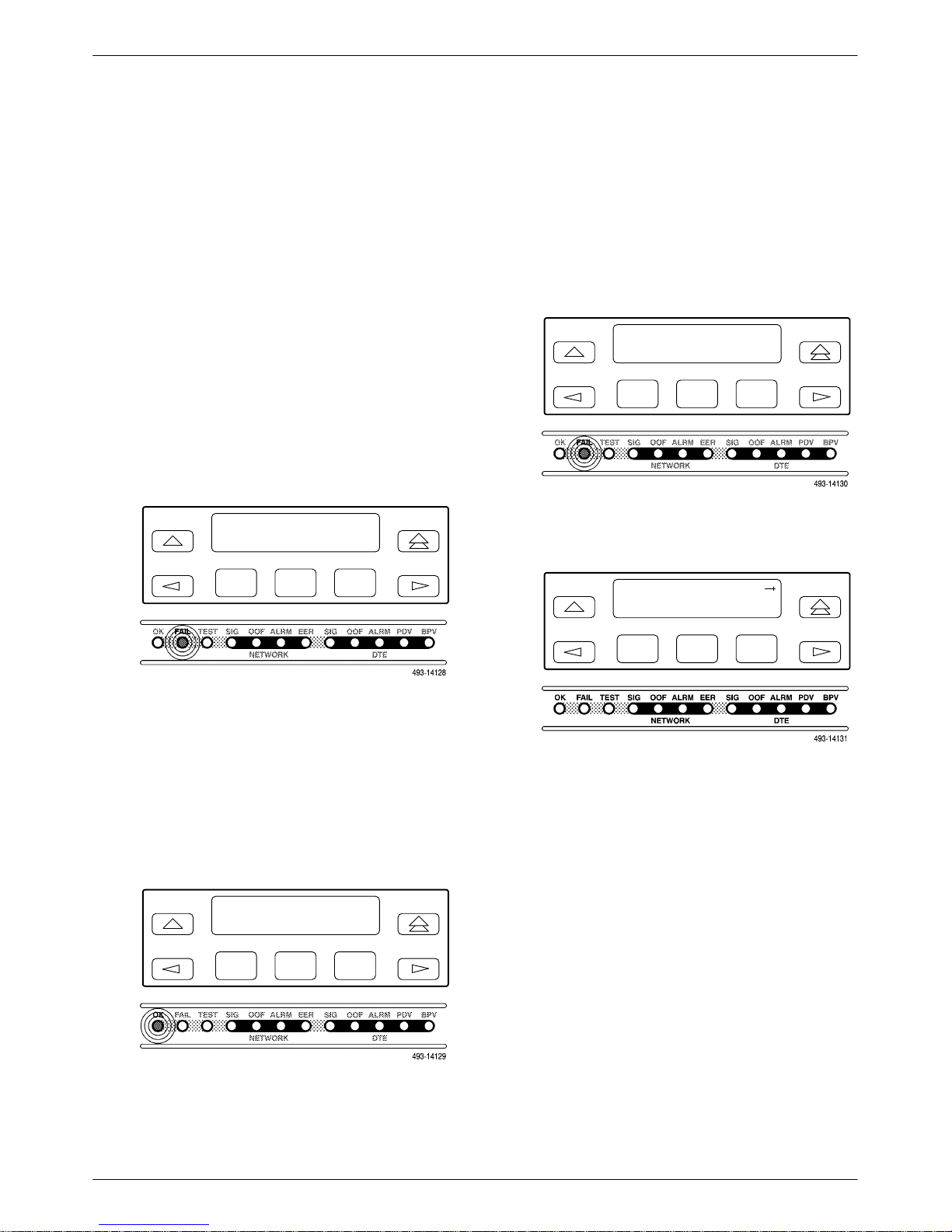
The power-up self-test consists of the following steps:
1. Once the CSU is plugged in, the In Progress
screen appears and the Fail LED blinks ON and
Off continuously.
Self-Test:
In Progress
F1
F2
F3
If the self-test fails, the Failed screen appears for
five seconds. The Fail LED lights, and an
eight-digit failure code (xxxxxxxx) is displayed for
use by service personnel to determine the cause of
the self-test failure. The CSU continues to try to
operate. If you are in doubt about the results of the
self-test, use the Self-T est Health command to
display the status of this test (see the Self-Test
Health section in Chapter 4, Maintenance).
Self-Test:
F1
xxxxxxxx
F2
F3
Failed
4. The top-level menu screen appears.
CSU ESF
Stat Test Cnfig
2. All the LEDs then start to flash simultaneously in
the pattern twice ON, then Off. Then, the LCD
begins to flash characters and numbers in the same
pattern, alternating with the flashing LEDs.
3. If the self-test is successful, the Passed screen
appears for one second, the Fail LED turns Off
and the OK LED lights.
Self-Test:
Passed
F1
F2
F3
F1
F2
F3
2-8 February 1998 3150-A2-GB21-80

Operation
Overview 3-2. . . . . . . . . . . . . . . . . . . . . . . . . . . . . . . . . . . . . . . . . . . . . . . . . . . . . . . . . . . . . . . . . . . . . . . . . .
Using the Front Panel 3-2. . . . . . . . . . . . . . . . . . . . . . . . . . . . . . . . . . . . . . . . . . . . . . . . . . . . . . . . . . . . . . . .
LCD 3-3. . . . . . . . . . . . . . . . . . . . . . . . . . . . . . . . . . . . . . . . . . . . . . . . . . . . . . . . . . . . . . . . . . . . . . . . . . .
Keypad. 3-3. . . . . . . . . . . . . . . . . . . . . . . . . . . . . . . . . . . . . . . . . . . . . . . . . . . . . . . . . . . . . . . . . . . . . . . .
Test Jacks. 3-4. . . . . . . . . . . . . . . . . . . . . . . . . . . . . . . . . . . . . . . . . . . . . . . . . . . . . . . . . . . . . . . . . . . . . .
LEDs 3-4. . . . . . . . . . . . . . . . . . . . . . . . . . . . . . . . . . . . . . . . . . . . . . . . . . . . . . . . . . . . . . . . . . . . . . . . . .
Displaying Unit Identity 3-7. . . . . . . . . . . . . . . . . . . . . . . . . . . . . . . . . . . . . . . . . . . . . . . . . . . . . . . . . . . . . .
Setting Customer Identification 3-8. . . . . . . . . . . . . . . . . . . . . . . . . . . . . . . . . . . . . . . . . . . . . . . . . . . . . . . .
Displaying LED Conditions 3-8. . . . . . . . . . . . . . . . . . . . . . . . . . . . . . . . . . . . . . . . . . . . . . . . . . . . . . . . . . .
Changing Configuration Options 3-9. . . . . . . . . . . . . . . . . . . . . . . . . . . . . . . . . . . . . . . . . . . . . . . . . . . . . . .
Displaying/Editing Configuration Options 3-10. . . . . . . . . . . . . . . . . . . . . . . . . . . . . . . . . . . . . . . . . . . . .
Saving Edit Changes 3-11. . . . . . . . . . . . . . . . . . . . . . . . . . . . . . . . . . . . . . . . . . . . . . . . . . . . . . . . . . . . . .
Configuring the CSU for SNMP or Telnet Access 3-11. . . . . . . . . . . . . . . . . . . . . . . . . . . . . . . . . . . . . . . . . .
Selecting the Port 3-11. . . . . . . . . . . . . . . . . . . . . . . . . . . . . . . . . . . . . . . . . . . . . . . . . . . . . . . . . . . . . . . . .
Setting the IP Address 3-12. . . . . . . . . . . . . . . . . . . . . . . . . . . . . . . . . . . . . . . . . . . . . . . . . . . . . . . . . . . . .
Selecting the Link Layer Protocol 3-13. . . . . . . . . . . . . . . . . . . . . . . . . . . . . . . . . . . . . . . . . . . . . . . . . . . .
Specifying the Community Name(s) and Access Type(s) 3-14. . . . . . . . . . . . . . . . . . . . . . . . . . . . . . . . . .
Configuring SNMP Traps 3-16. . . . . . . . . . . . . . . . . . . . . . . . . . . . . . . . . . . . . . . . . . . . . . . . . . . . . . . . . . . . .
Enabling SNMP Trap Messages 3-16. . . . . . . . . . . . . . . . . . . . . . . . . . . . . . . . . . . . . . . . . . . . . . . . . . . . .
Selecting the Number of Trap Managers 3-16. . . . . . . . . . . . . . . . . . . . . . . . . . . . . . . . . . . . . . . . . . . . . . .
Configuring a Destination for SNMP Traps 3-17. . . . . . . . . . . . . . . . . . . . . . . . . . . . . . . . . . . . . . . . . . . .
Establishing Access Security on a Port 3-18. . . . . . . . . . . . . . . . . . . . . . . . . . . . . . . . . . . . . . . . . . . . . . . . . . .
Setting a Password 3-18. . . . . . . . . . . . . . . . . . . . . . . . . . . . . . . . . . . . . . . . . . . . . . . . . . . . . . . . . . . . . . . . . .
Entering a Password to Gain Access 3-19. . . . . . . . . . . . . . . . . . . . . . . . . . . . . . . . . . . . . . . . . . . . . . . . . . . .
Acquiring/Releasing the User Interface 3-19. . . . . . . . . . . . . . . . . . . . . . . . . . . . . . . . . . . . . . . . . . . . . . . . . .
Acquiring the Active User Interface 3-19. . . . . . . . . . . . . . . . . . . . . . . . . . . . . . . . . . . . . . . . . . . . . . . . . .
Releasing the Active User Interface 3-20. . . . . . . . . . . . . . . . . . . . . . . . . . . . . . . . . . . . . . . . . . . . . . . . . .
Enabling/Disabling the Front Panel 3-20. . . . . . . . . . . . . . . . . . . . . . . . . . . . . . . . . . . . . . . . . . . . . . . . . . . . .
Using the Integral Modem in Standalone CSUs 3-21. . . . . . . . . . . . . . . . . . . . . . . . . . . . . . . . . . . . . . . . . . . .
Entering Numbers in the Phone Directories 3-21. . . . . . . . . . . . . . . . . . . . . . . . . . . . . . . . . . . . . . . . . . . .
Initiating a Call for Front Panel Pass-Through Operation 3-23. . . . . . . . . . . . . . . . . . . . . . . . . . . . . . . . . .
Initiating a Call for PC, ASCII Terminal/Printer, or SNMP Operation 3-23. . . . . . . . . . . . . . . . . . . . . . . .
Disconnecting the Modem Connection 3-24. . . . . . . . . . . . . . . . . . . . . . . . . . . . . . . . . . . . . . . . . . . . . . . .
Enabling the Communication Port for Carrier-Mounted CSUs 3-25. . . . . . . . . . . . . . . . . . . . . . . . . . . . . . . .
Deactivating the Alarm Relay for Carrier-Mounted CSUs 3-27. . . . . . . . . . . . . . . . . . . . . . . . . . . . . . . . . . . .
Resetting the CSU 3-27. . . . . . . . . . . . . . . . . . . . . . . . . . . . . . . . . . . . . . . . . . . . . . . . . . . . . . . . . . . . . . . . . . .
Download Operations 3-27. . . . . . . . . . . . . . . . . . . . . . . . . . . . . . . . . . . . . . . . . . . . . . . . . . . . . . . . . . . . . . . .
3
3-13150-A2-GB21-80 February 1998
ACCULINK 315x CSU
8
Overview
This chapter contains information for operating your
CSU. It includes a description of the front panel and
sample procedures for configuring the CSU.
NOTE
Additional information for the
carrier-mounted CSU is located in
the
ACCULINK 3151 CSU and
3161 DSU/CSU General
Information Guide
COMSPHERE 3000 Series
Carrier Installation Manual
and the
.
Using the Front Panel
The standalone CSU front panel (Figure 3-1) consists
of an LCD, a keypad, test jacks, and 12 LEDs. The
carrier-mounted CSU faceplate contains test jacks and
12 LEDs, however, the LCD and keypad are located on
the Shared Diagnostic Control Panel (SDCP) of the
3000 Series Carrier. For more information about the
SDCP, refer to the COMSPHERE 3000 Series Carrier
Installation Manual.
NOTE
You can display a graphical
representation of the CSU front
panel on an attached PC (see
Appendix G,
Emulation
LCD
Front Panel
).
ACCULINK
3150
NET MON EQPT
In
OutInOutInOut
F1 F2 F3
OK
FAIL TEST SIG OOF ALRM
NETWORK
EER SIG ALRM PDVOOF BPV
Figure 3-1. Standalone CSU Front Panel
DTE
496-1493
3-2 February 1998 3150-A2-GB21-80
Operation
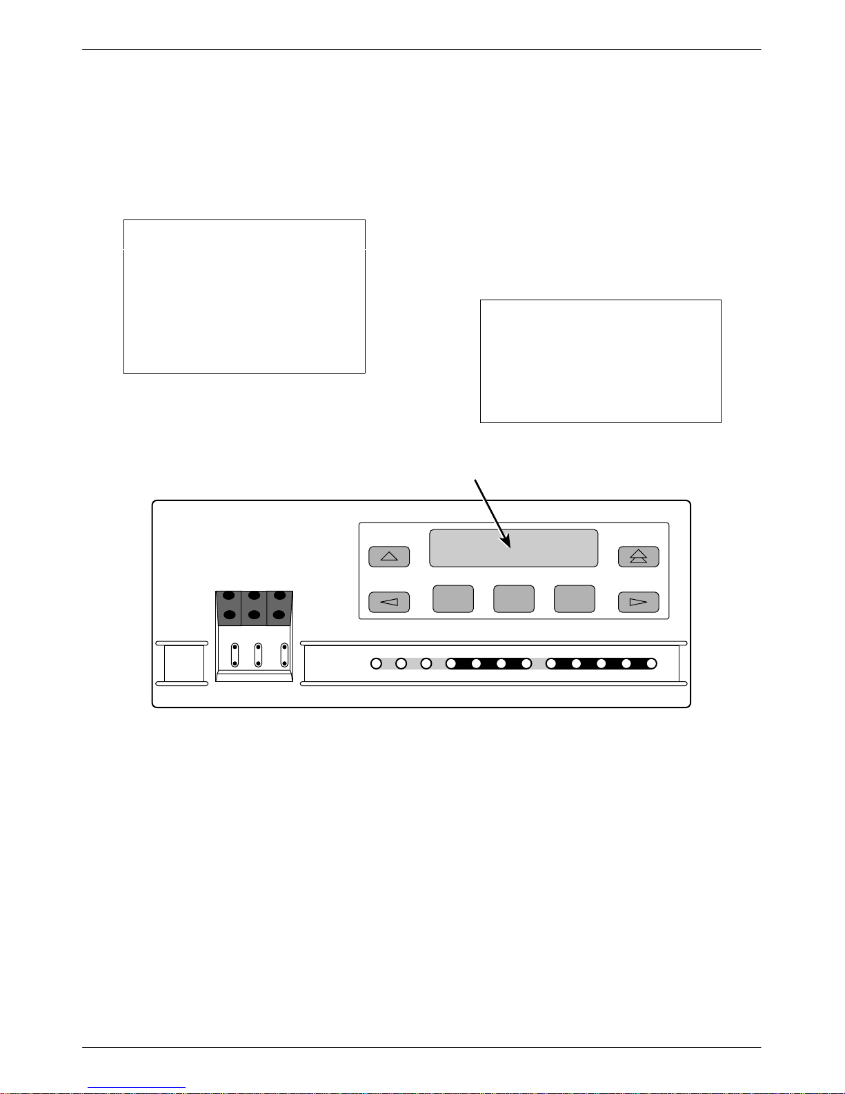
LCD
The LCD (Figure 3-2) displays two types of data:
• Messages such as alarms, command/test
completion, and action in progress
• Front panel menu tree information (see
Appendix A, Front Panel Menu)
F1 F2
Figure 3-2. LCD
The LCD displays status messages as requested via the
Device Health and Status branch of the front panel menu
(see the Device Health and Status section in Chapter 4,
Maintenance). In addition, the highest level status
message appears on the front panel automatically if no
front panel action has occurred at the CSU for the past
five minutes.
The LCD also lists commands, configuration options,
and test results. In most cases, the top line shows the
command or option name and default value, while the
second line displays options and responses. When a
response is required, select from the options displayed
directly above the Function keys (F1, F2, F3); make your
choice by pressing the corresponding Function key.
F3
Keypad
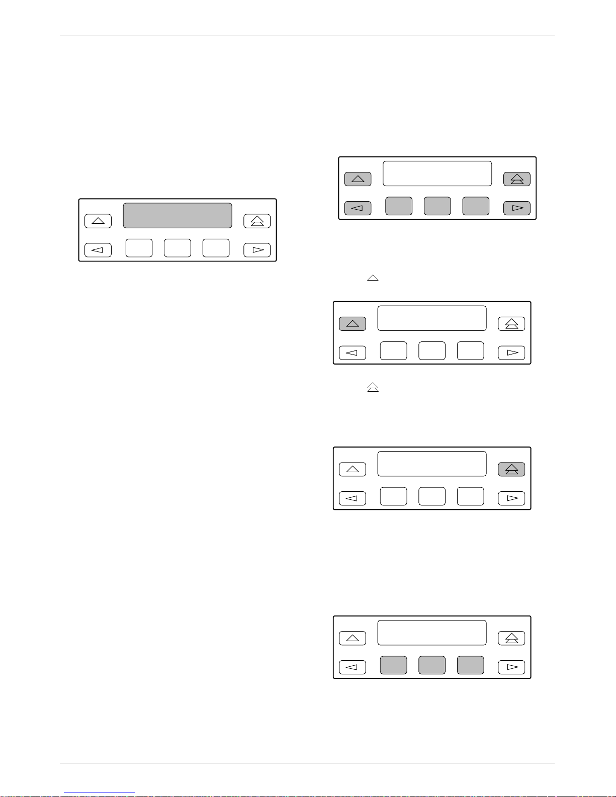
The 7-button keypad (Figure 3-3) enables you to
navigate through the menu tree and select choices
presented on the second line of the LCD.
F1 F2
Figure 3-3. Keypad
Use the
key to move up the menu.
F1 F2
Use the key to exit any part of the menu in which
you may be operating. You immediately return to the
top-level menu screen shown on the front panel menu (see
Appendix A, Front Panel Menu).
F3
F3
F1 F2
F3
Use the Function (F1, F2, F3) keys to make selections
from the choices presented on the second line of the LCD.
When this line presents choices, it is generally divided
into three sections, each displayed directly above one of
the Function keys. When your choice appears above one
of the Function keys, press that key to select that choice.
F1 F2
F3
3-33150-A2-GB21-80 February 1998
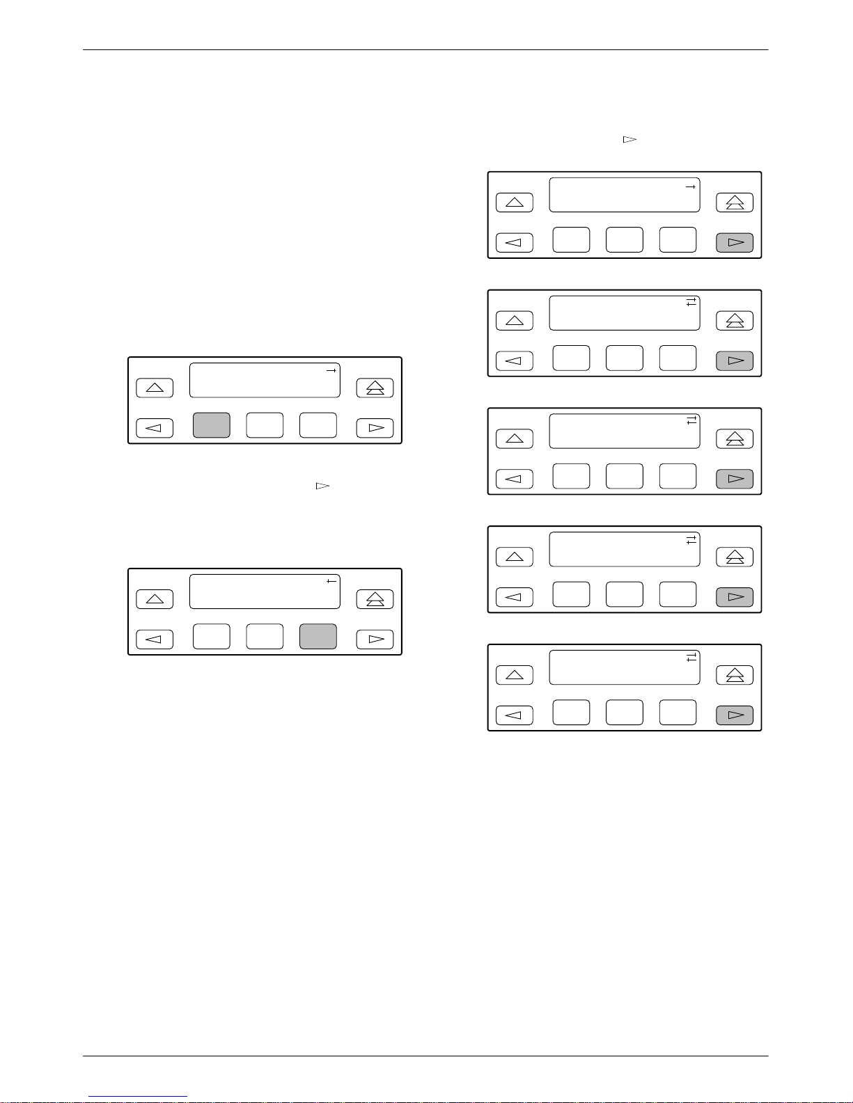
ACCULINK 315x CSU
8
The scroll keys ( and ) serve one of two functions,
depending on whether a menu screen or a data entry
screen appears on the front panel.
For data entry screens, the
character to the left while the
key scrolls one
key scrolls one
character to the right.
For menu screens, the
menu choice while the
key scrolls to the previous
key scrolls to the next menu
choice.
F1 F2
F3
If a choice is available to the left of the screen, the
character ← appears on the top line. If a choice is
available to the right of the screen, the → character
appears on the top line. If choices are available to both the
right and the left of the screen, two arrows appear (
).
The arrows indicate that you must use the scroll keys to
bring the additional options onto the screen.
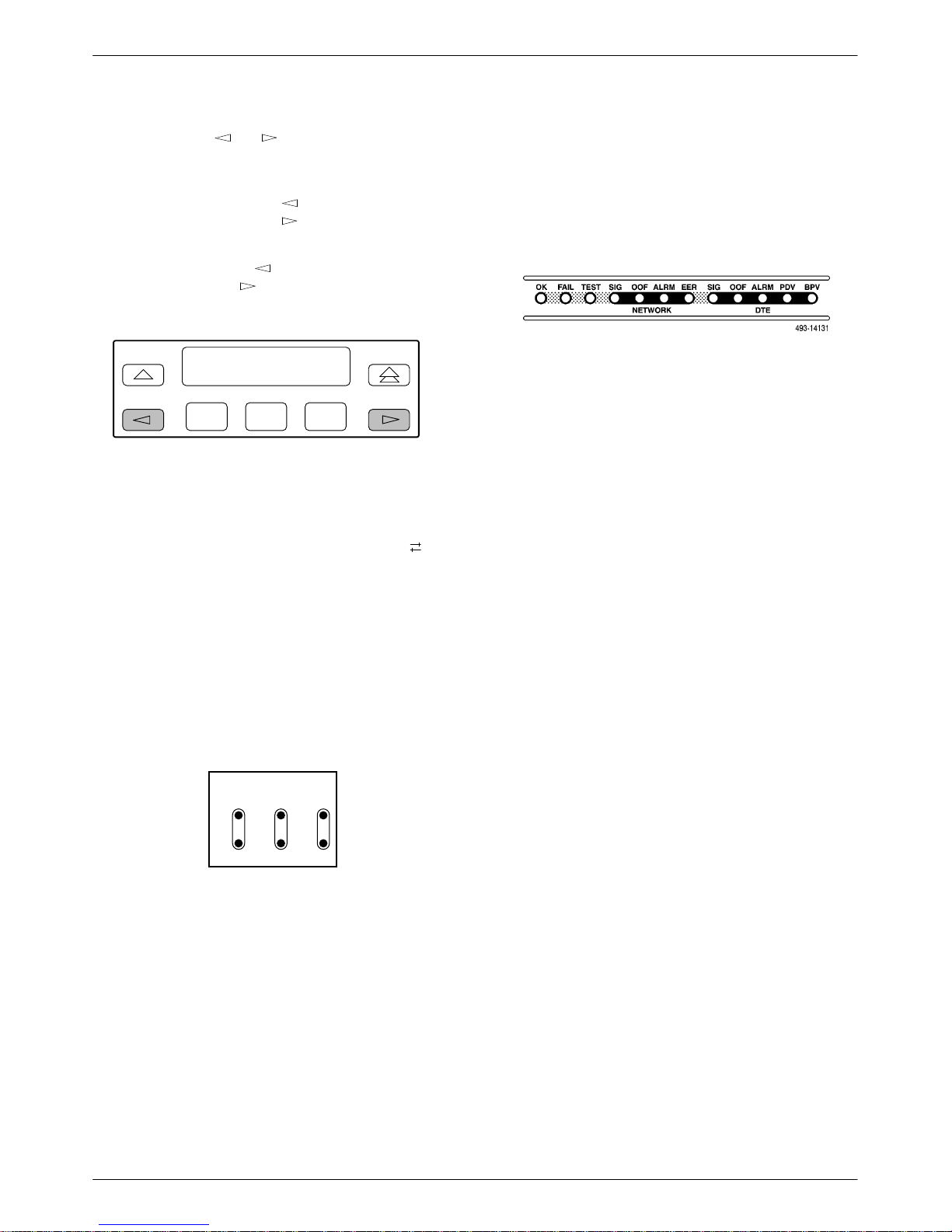
LEDs
There are twelve LEDs on the CSU front panel
(Figure 3-5). A green LED indicates normal operation. A
yellow LED indicates a warning. Conditions are sampled
every tenth of a second.
Figure 3-5. CSU LEDs
The twelve front panel LEDs are grouped into three
sections to indicate the status of the:
• System (Table 3-1)
• Network interface (Table 3-2)
• DTE interface (T able 3-3)
Test Jacks
T est jacks are located on the CSU front panel
(Figure 3-4). These are described in the Test Jacks section
in Chapter 4, Maintenance.
NET MON EQPT
In
OutInOutInOut
496-1480
Figure 3-4. Test Jacks (Standalone CSU)
3-4 February 1998 3150-A2-GB21-80

Table 3-1
System LEDs
Operation
Name
OK Green Indicates the current operational state of the CSU.
FAIL Yellow Indicates a system failure or a self-test.
TEST Yellow A system test is in progress.
Color Meaning
ON:
OFF:
BLINKING:
FAST BLINK:
ON:
OFF:
BLINKING
ON:
OFF:
The CSU is operational and has power.
The CSU is performing a power-up self-test or a system failure has
occurred.
A software download is in progress.
The carrier-mounted CSU is currently selected by the SDCP.
A device error/fault is detected or a reset has just occurred.
No system failures are detected.
: A self-test is in progress.
A loopback or pattern test has been initiated either locally , by the
network, or externally .
No tests are active.
Table 3-2
Network Interface LEDs
Name
SIG Green Monitors the signal being received from the network.
OOF Yellow Monitors Out Of Frame (OOF) conditions on the received network signal.
ALRM Yellow Indicates whether an alarm condition exists on the received network signal.
EER Yellow Indicates the Excessive Error Rate (EER) has been exceeded on the network interface.
Color Meaning
ON:
OFF:
ON
: At least one OOF was detected on the signal during the sampling
OFF:
ON:
OFF:
NOTE: This LED is only valid when ESF framing is being used.
ON:
OFF:
A recoverable signal is being received from the network.
The signal cannot be recovered from the network (a Loss of Signal
condition exists).
period.
No OOFs were detected on the signal during the sampling period.
An alarm condition (LOS, LOF, EER, Yellow, AIS) exists on the
received network signal. Use the Device Health and Status
command to determine the alarm type.
No alarm condition exists on the network interface signal.
The EER has been exceeded on the network interface.
The EER has not been exceeded on the network interface.
3-53150-A2-GB21-80 February 1998

ACCULINK 315x CSU
Table 3-3
DTE Interface LEDs
Name
SIG Green Monitors the signal being received from the T1 DTE interface.
OOF Yellow Monitors Out Of Frame (OOF) conditions on the received T1 DTE interface signal.
ALRM Yellow Indicates whether an alarm condition exists on the received T1 DTE interface signal.
PDV Yellow Monitors Pulse Density Violations (PDV) on the received T1 DTE interface signal.
BPV Yellow Monitors Bipolar Violations (BPV) on the received T1 DTE interface signal.
Color Meaning
ON:
OFF:
ON:
OFF:
ON:
OFF:
ON
: At least one PDV was detected (and corrected) on the received T1
OFF:
ON:
OFF:
A recoverable signal is being received from the T1 DTE interface.
The signal cannot be recovered from the T1 DTE interface (a Loss
of Signal condition exists).
At least one OOF was detected on the signal during the sampling
period.
No OOFs were detected on the signal during the sampling period.
An alarm condition (LOS, LOF, EER, Yellow, AIS) exists on the
received T1 DTE interface signal. Use the Device Health and Status
command to determine the alarm type.
No alarm condition exists on the T1 DTE interface signal.
DTE interface signal during the sampling period.
No PDVs were detected on the received T1 DTE interface signal
during the sampling period.
At least one BPV was detected (and corrected) on the received T1
DTE interface signal during the sampling period.
No BPVs were detected on the received T1 DTE interface signal
during the sampling period.
3-6 February 1998 3150-A2-GB21-80
Operation
Displaying Unit Identity
The identity of the CSU (serial number, model number,
software revision level, hardware revision level, and
customer identification) is available through the Status
branch of the front panel menu (see Appendix A, Front
Panel Menu).
The customer identification is the only identity number
you can change.
T o display the CSU’s identity (ID),
1. From the top-level menu screen, select Stat.
CSU ESF
Stat Test Cnfig
F1
F2
2. From the Status screen, press the key until the
ID selection appears on the screen.
F3
4. The following screens appear in the order listed
each time you press the
key.
Identity:
xxxxxxx
Ser=
F1
F2
F3
Identity:
xxxx-xx-xxx
Mod=
F1
F2
F3
Identity:
Cust ID=
F1
xxxxxxxx
F2
F3
3. Select ID.
Status:
TStat LED ID
F1
F2
F3
Identity:
SRev=
F1
Identity:
xxxx-xxx
CCA=
F1
xx.xx.xx
F2
F2
F3
F3
3-73150-A2-GB21-80 February 1998
ACCULINK 315x CSU
Setting Customer
Identification
The customer identification is the only identity number
you can change. It is used to uniquely identify the CSU.
NOTE
The following procedure is an
example only. Screen displays
may vary depending on the
model of the CSU.
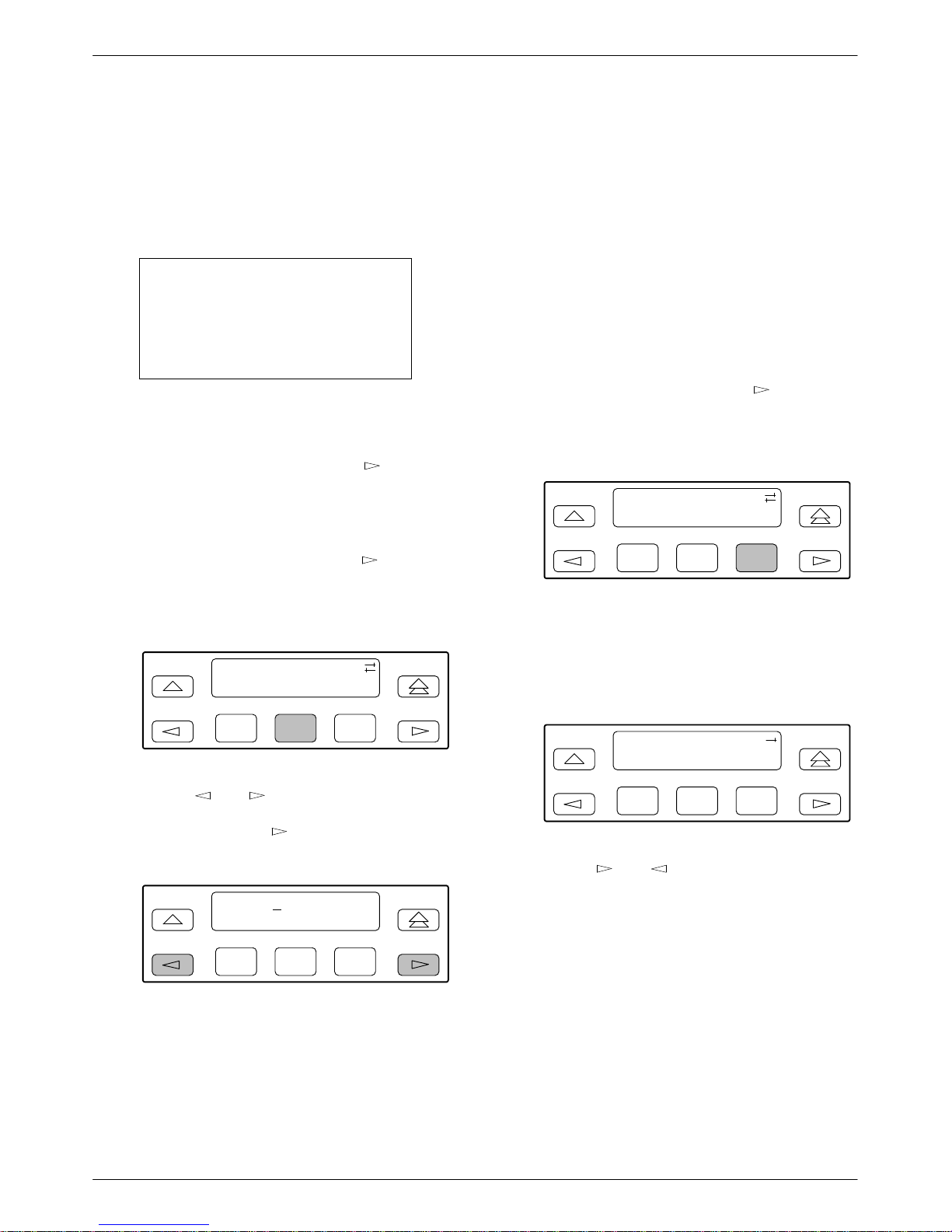
T o change the customer identification (CID),
1. From the top-level menu, press the
the Ctrl selection appears on the screen.
2. Select Ctrl.
3. From the Control screen, press the
the CID selection appears on the screen.
key until
key until
Displaying LED Conditions
The same conditions monitored by the front panel
LEDs can also be monitored by the LED command. This
command is most useful when the CSU is being accessed
remotely (see Appendix G, Front Panel Emulation).
When using Front Panel Emulation, no LEDs are shown
on the PC’s screen; you must use the Stat command
procedure described below to get LED information.
T o display LED conditions on the front panel screen,
1. From the top-level menu screen, select Stat.
2. From the Status screen, press the
LED selection appears on the screen.
3. From the Status screen, select LED.
Status:
Perf TStat LED
F1
F2
key until the
F3
4. Select CID.
Control:
Reset CID Passwd
F1
F2
F3
5. Use the and keys to position the cursor
under the desired character. You must enter a
character before the
moves the cursor to the
next space to the right.
CustID:
xxxxxxxx
Up Down Save
F1
F2
F3
6. Enter the desired ID. Press F1 (Up) and F2
(Down) to scroll up and down through the valid
characters/numbers for the customer ID. Valid
characters are 0 through 9, #, -, ., /, A to Z, and
blank space. Press F3 (Save) to save the ID.
The LED Display screen lists the LED signals,
two at a time, on the second line. A vertical bar at
the left of the LED name indicates the condition is
ON, while an underscore indicates the condition is
Off.
LED Display:
_Test _NetSig
F1
F2
F3
4. Use the and keys to scroll LED names
onto the screen.
3-8 February 1998 3150-A2-GB21-80
 Loading...