

Page 1

Command Line Interface
for 1813 and 1823 VoIP Gateways,
1862 SIP IAD, and 6212-A1 Router
User’s Guide
Document Number 1800-A2-GB20-00
June 2005
Page 2

Command Line Interface User’s Guide
Copyright 2005 Paradyne Corporation.
All rights reserved.
Printed in U.S.A.
Notice
This publication is protected by federal copyright law. No part of this publication may be copied or distributed,
transmitted, transcribed, stored in a retrieval system, or translated into any human or computer language in any form
or by any means, electronic, mechanical, magnetic, manual or otherwise, or disclosed to third parties without the
express written permission of Paradyne Corporation, 8545 126th Ave. N., Largo, FL 33773.
Paradyne Corporation makes no representation or warranties with respect to the contents hereof and specifically
disclaims any implied warranties of merchantability or fitness for a particular purpose. Further, Paradyne Corporation
reserves the right to revise this publication and to make changes from time to time in the contents hereof without
obligation of Paradyne Corporation to notify any person of such revision or changes.
Changes and enhancements to the product and to the information herein will be documented and issued as a new
release to this manual.
Warranty, Sales, Service, and Training Information
Contact your local sales representative, service representative, or distributor directly for any help needed. For
additional information concerning warranty, sales, service, repair, installation, documentation, training, distributor
locations, or Paradyne worldwide office locations, use one of the following methods:
Internet: Visit the Paradyne World Wide Web site at www.paradyne.com. (Be sure to register your warranty at
www.paradyne.com/warranty.)
Telephone: Call our automated system to receive current information by fax or to speak with a company
representative.
Within the U.S.A., call 1-800-870-2221
Outside the U.S.A., call 1-727-530-2340
Document Feedback
We welcome your comments and suggestions about this document. Please mail them to Technical Publications,
Paradyne Corporation, 8545 126th Ave. N., Largo, FL 33773, or send e-mail to userdoc@paradyne.com. Include
the number and title of this document in your correspondence. Please include your name and phone number if you
are willing to provide additional clarification.
Trademarks
Acculink, ADSL/R, Bitstorm, Comsphere, DSL the Easy Way, ETC, Etherloop, FrameSaver, GranDSLAM,
GrandVIEW, Hotwire, the Hotwire logo, Jetstream, MVL, NextEDGE, Net to Net Technologies, OpenLane, Paradyne,
the Paradyne logo, Paradyne Credit Corp., the Paradyne Credit Corp. logo, Performance Wizard, ReachDSL,
StormPort, TruePut are registered trademarks of Paradyne Corporation. Connect to Success, Hotwire Connected,
iMarc, JetFusion, JetVision, MicroBurst, PacketSurfer, Quick Channel, Reverse Gateway, Spectrum Manager, and
StormTracker are trademarks of Paradyne Corporation. All other products and services mentioned herein are the
trademarks, service marks, registered trademarks, or registered service marks of their respective owners.
2 1800-A2-GB20-00
Page 3

Command Line Interface User’s Guide
Preface
This instruction guide introduces the command line interface (CLI) for the Telnet management
of the 1813 and 1823 VoIP Gateways, the 1862 SIP IAD, and 6212 Router. If your device has a
console port, you can also access the CLI from a VT100 terminal or equivalent (such as a PC
running Hyperterminal or Telix).
This manual is written for a range of ADSL products. Some specific commands may not be
available for all devices. For example, wireless functions will only be available for products with
wireless functionality.
See the user’s guide for your device for information about web-based management.
1800-A2-GB20-00 3
Page 4

Command Line Interface User’s Guide
Table of Contents
CHAPTER 1 TELNET ACCESS ......................................................................................... 10
1.1 SETTING A COMMON IP ADDRESS.................................................................................. 10
1.2 LOGIN ............................................................................................................................ 12
CHAPTER 2 GENERAL OPERATION.............................................................................. 13
2.1 CLI REFERENCE............................................................................................................. 13
2.2 G
2.2.1 ls............................................................................................................................ 14
2.2.2 help........................................................................................................................ 14
2.2.3 accountstats........................................................................................................... 15
2.2.4 exit......................................................................................................................... 15
2.2.5 version................................................................................................................... 15
2.2.6 date........................................................................................................................ 16
2.2.7 erase...................................................................................................................... 16
2.2.8 save ....................................................................................................................... 16
2.2.9 reboot.................................................................................................................... 16
2.2.10 ping .......................................................................................................................16
2.2.11 time........................................................................................................................ 17
2.3
2.3.1 logSeverity............................................................................................................. 18
2.3.2 log .........................................................................................................................18
2.3.3 logFtpServer ......................................................................................................... 19
2.3.4 loginfo................................................................................................................... 19
2.4 U
2.5 E
2.5.1 Primary IP address............................................................................................... 24
2.5.2 Alias IP Address.................................................................................................... 25
2.6 R
2.6.1 add......................................................................................................................... 25
2.6.2 delete..................................................................................................................... 26
2.6.3 list.......................................................................................................................... 26
2.6.4 rarpd .....................................................................................................................27
2.7
2.8
ENERIC ........................................................................................................................ 14
LOGGER.......................................................................................................................... 18
SER ACCOUNT ............................................................................................................. 20
THERNET IP ADDRESS ................................................................................................. 23
ARPD ........................................................................................................................... 25
TIMEOUT ........................................................................................................................ 27
BAUDRATE ..................................................................................................................... 27
CHAPTER 3 QUICK CONFIGURATION.........................................................................29
3.1 RFC
1483 BRIDGED....................................................................................................... 29
3.1.1 PART 1 Create a PVC........................................................................................... 29
3.1.2 PART 2 Set the PVC to RFC 1483 Bridged..........................................................29
3.1.3 PART 3 Delete the PVC for RFC1483 Bridged....................................................30
3.2 RFC
1483 ROUTED........................................................................................................30
3.2.1 PART 1 Create a new VC...................................................................................... 30
3.2.2 PART 2 Set the PVC to RFC 1483 Routed............................................................ 31
4 1800-A2-GB20-00
Page 5

Command Line Interface User’s Guide
3.2.3 PART 3 Set up an IP address for the WAN interface............................................ 31
3.2.4 PART 4 Delete the PVC to RFC 1483 Routed...................................................... 31
3.3 IP
OA.............................................................................................................................. 32
3.3.1 PART 1 create a new PVC.................................................................................... 32
3.3.2 PART 2 Set the PVC to IPoA ................................................................................ 32
3.3.3 PART 3 Delete the PVC for IPoA......................................................................... 33
3.4 PPP
OE........................................................................................................................... 33
3.4.1 PART 1 Create a new VC...................................................................................... 33
3.4.2 PART 2 Set the PVC to PPPoE............................................................................. 33
3.4.3 PART 3 Delete the PVC for PPPoE...................................................................... 34
3.5 PPP
OA........................................................................................................................... 35
3.5.1 PART 1 Create a new VC...................................................................................... 35
3.5.2 PART 2 Set the PVC to PPPoA............................................................................. 35
3.5.3 PART 3 Delete the PVC for PPPoA...................................................................... 36
3.6 MER.............................................................................................................................. 36
3.6.1 PART 1 Create a new VC...................................................................................... 36
3.6.2 PART 2 Set the PVC to MER ................................................................................ 36
3.6.3 PART 3 Set up an IP address for the WAN interface............................................ 37
3.6.4 PART 4 Delete the PVC for MER......................................................................... 37
CHAPTER 4 COMMAND LINE INTERFACE SIP.......................................................... 38
4.1 SIP
HOST (USER AGENT)............................................................................................. 38
4.1.1 Configuration........................................................................................................ 38
4.1.2 Displaying............................................................................................................. 38
4.2 SIP
PROXY/REGISTRAR SERVER....................................................................................39
4.2.1 Configuration........................................................................................................ 39
4.2.2 Displaying............................................................................................................. 39
4.3 SIP
DOMAIN .................................................................................................................. 39
4.3.1 Configuration........................................................................................................ 39
4.3.2 Displaying............................................................................................................. 40
4.4 C
ODECS SUPPORTED ...................................................................................................... 40
4.4.1 Configuration........................................................................................................ 40
4.4.2 Displaying............................................................................................................. 41
4.5 P
HONE ........................................................................................................................... 41
4.5.1 Configuration........................................................................................................ 41
4.5.2 Displaying............................................................................................................. 42
4.5.3 Configuration........................................................................................................ 42
4.5.4 Displaying............................................................................................................. 43
4.5.5 Deleting................................................................................................................. 43
4.6 C
ALL FORWARD............................................................................................................. 43
4.6.1 Configuration........................................................................................................ 43
4.6.2 Displaying............................................................................................................. 44
4.7 A
UTHENTICATION.......................................................................................................... 44
4.7.1 Configuration........................................................................................................ 44
4.7.2 Displaying............................................................................................................. 45
4.8 R
4.9 I
EGISTRATION............................................................................................................... 45
NTER-DIGIT TIMEOUT ...................................................................................................46
1800-A2-GB20-00 5
Page 6

Command Line Interface User’s Guide
4.10 MAX RINGS.................................................................................................................... 46
4.11 D
4.12 V
IAL PLAN..................................................................................................................... 47
OICE CONFIGURATION................................................................................................. 47
4.12.1 Voice Options........................................................................................................ 47
4.12.2 Jitter Buffer Configuration ................................................................................... 48
4.12.3 Country ................................................................................................................. 48
4.13 P
HONE OPERATIONS ...................................................................................................... 48
4.13.1 Normal Call Hold .................................................................................................48
4.13.2 Consultation Call Hold......................................................................................... 49
4.13.3 Call Resume.......................................................................................................... 49
4.13.4 Call Switch............................................................................................................ 49
4.13.5 Call Waiting.......................................................................................................... 49
CHAPTER 5 ADVANCED CONFIGURATION................................................................ 50
5.1 S
5.2 E
TATIC ROUTE...............................................................................................................50
THERNET...................................................................................................................... 51
5.2.1 MAC Address........................................................................................................ 51
5.2.2 rmon...................................................................................................................... 52
5.2.3 pread..................................................................................................................... 52
5.2.4 pwrite .................................................................................................................... 52
5.2.5 elink....................................................................................................................... 53
5.2.6 Ethernet up/down..................................................................................................54
5.3 B
RIDGE .......................................................................................................................... 54
5.3.1 arpproxy................................................................................................................ 54
5.3.2 pvc......................................................................................................................... 55
5.3.3 group..................................................................................................................... 55
5.3.4 group3................................................................................................................... 56
5.3.5 cachetimer............................................................................................................. 57
5.3.6 setmultiport........................................................................................................... 57
5.3.7 list.......................................................................................................................... 58
5.3.8 stats....................................................................................................................... 58
5.3.9 bridge.................................................................................................................... 58
5.3.10 vstats ..................................................................................................................... 58
5.3.11 vlantable................................................................................................................ 59
5.3.12 vlanmode............................................................................................................... 59
5.3.13 fdbmode................................................................................................................. 60
5.3.14 igmpsnooping........................................................................................................ 60
5.3.15 stp.......................................................................................................................... 60
5.3.16 filter....................................................................................................................... 62
5.3.17 filterlist.................................................................................................................. 63
5.3.18 filterflush............................................................................................................... 63
5.3.19 l2_list..................................................................................................................... 63
5.3.20 l2_fil...................................................................................................................... 63
5.4 SNMP............................................................................................................................ 65
5.4.1 list.......................................................................................................................... 66
5.4.2 sysconf................................................................................................................... 66
5.4.3 shutdown............................................................................................................... 67
6 1800-A2-GB20-00
Page 7

Command Line Interface User’s Guide
5.4.4 start....................................................................................................................... 67
5.4.5 comconf................................................................................................................. 67
5.4.6 delcomm................................................................................................................ 67
5.4.7 trapconf................................................................................................................. 68
5.4.8 trap........................................................................................................................ 68
5.4.9 agconfig................................................................................................................. 69
5.5 F
IREWALL...................................................................................................................... 69
5.5.1 policy..................................................................................................................... 69
5.5.2 policy delete.......................................................................................................... 70
5.5.3 policy modify......................................................................................................... 70
5.5.4 policy enable......................................................................................................... 71
5.5.5 policy disable........................................................................................................ 71
5.5.6 policy list............................................................................................................... 71
5.5.7 nat ......................................................................................................................... 71
5.5.8 publicip .................................................................................................................72
5.5.9 links....................................................................................................................... 72
5.5.10 nataction ...............................................................................................................73
5.5.11 spoof...................................................................................................................... 73
5.5.12 setwt ...................................................................................................................... 74
5.5.13 listwt...................................................................................................................... 74
5.5.14..................................................................................................................................... 74
5.5.15 Attach....................................................................................................................75
5.5.16 listwfq.................................................................................................................... 76
5.5.17 remove................................................................................................................... 76
5.5.18 qstat....................................................................................................................... 77
5.5.19 createtc.................................................................................................................. 77
5.5.20 deletetc.................................................................................................................. 77
5.5.21 listtc....................................................................................................................... 78
5.5.22 tcstat...................................................................................................................... 78
5.5.23 firewall.................................................................................................................. 78
5.5.24 attack..................................................................................................................... 78
5.6 NAPT............................................................................................................................ 79
5.6.1 natif....................................................................................................................... 80
5.6.2 links....................................................................................................................... 80
5.6.3 nat ......................................................................................................................... 80
5.6.4 addressmap........................................................................................................... 82
5.6.5 portmap................................................................................................................. 83
5.6.6 delrdaddr............................................................................................................... 84
5.6.7 maplist................................................................................................................... 85
5.6.8 addpublic............................................................................................................... 85
5.6.9 delpublic................................................................................................................ 86
5.6.10 listpubaddrs........................................................................................................... 86
5.7 HTTP
5.8 DHCP
PROXY.................................................................................................................86
SERVER............................................................................................................... 87
5.8.1 start....................................................................................................................... 87
5.8.2 stop........................................................................................................................ 88
1800-A2-GB20-00 7
Page 8

Command Line Interface User’s Guide
5.8.3 subnet.................................................................................................................... 88
5.8.4 host........................................................................................................................ 89
5.8.5 lease ...................................................................................................................... 90
5.9 DHCP
RELAY................................................................................................................. 90
5.10 ADSL............................................................................................................................ 91
5.10.1 setmode ................................................................................................................. 91
5.10.2 readcmv................................................................................................................. 91
5.10.3 writecmv................................................................................................................ 92
5.10.4 mon........................................................................................................................ 92
5.10.5 addusercmv........................................................................................................... 92
5.10.6 delusercmv ............................................................................................................ 93
5.10.7 listusercmv ............................................................................................................ 93
5.10.8 eread .....................................................................................................................93
5.10.9 ewrite..................................................................................................................... 93
5.10.10 mwrite ............................................................................................................... 94
5.10.11 mread ................................................................................................................ 94
5.10.12 adslup................................................................................................................ 94
5.10.13 adsldown........................................................................................................... 94
5.10.14 tone.................................................................................................................... 95
5.10.15 bitalloc .............................................................................................................. 95
5.10.16 adslstat.............................................................................................................. 95
5.11 ADSL2+
CLI................................................................................................................. 96
5.11.1 Configuration........................................................................................................ 96
5.11.2 Displaying............................................................................................................. 97
5.12 DNS............................................................................................................................... 98
5.12.1 list.......................................................................................................................... 98
5.12.2 set.......................................................................................................................... 98
5.12.3 dnsr .......................................................................................................................99
5.13 IGMP
5.14 R
PROXY............................................................................................................... 100
IP...............................................................................................................................101
5.14.1 rip........................................................................................................................ 101
5.14.2 ver .......................................................................................................................101
5.14.3 list........................................................................................................................ 101
5.15 SNDCP........................................................................................................................ 102
5.15.1 pppoe................................................................................................................... 102
5.15.2 pppoedefault........................................................................................................ 104
5.15.3 pppoestart ........................................................................................................... 105
5.15.4 pppoestop............................................................................................................105
5.15.5 pppoelist.............................................................................................................. 105
5.15.6 pppoedel.............................................................................................................. 105
5.15.7 pppoa................................................................................................................... 105
5.15.8 pppoastart........................................................................................................... 107
5.15.9 pppoastop............................................................................................................ 107
5.15.10 pppoalist.......................................................................................................... 107
5.15.11 pppoadel.......................................................................................................... 107
5.15.12 pppoadefault ................................................................................................... 108
8 1800-A2-GB20-00
Page 9

Command Line Interface User’s Guide
5.15.13 list.................................................................................................................... 108
5.15.14 ipoa .................................................................................................................108
5.15.15 routedbridge.................................................................................................... 110
5.15.16 1483mer .......................................................................................................... 110
5.15.17 mer .................................................................................................................. 111
5.15.18 relay ................................................................................................................ 111
5.15.19 liststat.............................................................................................................. 112
5.15.20 ppptrace .......................................................................................................... 112
5.16
ATM ............................................................................................................................. 112
5.16.1 showatmconn....................................................................................................... 113
5.16.2 vcadd................................................................................................................... 113
5.16.3 vpadd................................................................................................................... 114
5.16.4 deletevc ............................................................................................................... 115
5.16.5 atmstats............................................................................................................... 115
5.16.6 f5lb ...................................................................................................................... 115
5.17
5.18 ACL
REMOTE WEB/TELNET/FTP/SNMP .................................................................................. 116
(ACCESS CONTROL LIST) .................................................................................... 116
5.18.1 addacl.................................................................................................................. 116
5.18.2 deleteacl.............................................................................................................. 118
5.18.3 listacls................................................................................................................. 119
CHAPTER 6 PERFORMANCE MONITORING ............................................................120
6.1 B
6.2 S
ITMAP........................................................................................................................120
TATISTIC .................................................................................................................... 121
CHAPTER 7 TFTP UPLOAD & DOWNLOAD............................................................... 122
7.1 U
7.2 A
7.3 U
7.4 U
7.5 D
PLOADING THE SOFTWARE FILE ................................................................................. 123
UTO UPGRADE........................................................................................................... 124
PLOADING THE CONFIGURATION FILE ........................................................................ 124
PGRADING THE SOFTWARE ........................................................................................ 126
OWNLOADING THE CONFIGURATIONS........................................................................ 127
CHAPTER 8 WIRELESS LAN.......................................................................................... 128
8.1 W
8.2 W
8.3 C
IRELESS LAN CONFIGURATION................................................................................ 128
IRELESS ASSOCIATION.............................................................................................. 132
OMMAND LINE INTERFACE ........................................................................................ 132
8.3.1 disassoc............................................................................................................... 132
8.3.2 association .......................................................................................................... 132
8.3.3 remaintime .......................................................................................................... 132
8.3.4 listdevices............................................................................................................ 133
8.3.5 Example............................................................................................................... 133
8.4 W
IRELESS LAN BATCH CONFIGURATION.................................................................... 134
1800-A2-GB20-00 9
Page 10

Command Line Interface User’s Guide
Chapter 1 Telnet Access
The Command Line Interface (CLI) can be used to configure your endpoint device. Telnet is
used to access the CLI.
To Telnet to the device, you can either set your PC’s IP address to the same domain as the
endpoint, or set the endpoint’s IP address to the same domain as your PC. The default IP address
of the endpoint is 192.168.1.1.
The timeout period of the Telnet session is three minutes. If no command is entered for three
minutes, the Telnet session is terminated.
1.1 Setting a Common IP Address
To log on to the device using Telnet, your PC and the endpoint should both be on the same
network segment. You can either modify the IP address of your PC to the same domain of the
endpoint, or modify the IP address of the endpoint to the same domain as your PC.
You can modify the IP address of the endpoint by completing the following steps:
STEP 1: Enter a management tool (http or cli) for your endpoint
STEP 2: Change the IP address to the same domain as your workstation.
STEP 3: Save the settings to the flash and reboot the endpoint.
10 1800-A2-GB20-00
Page 11
Command Line Interface User’s Guide
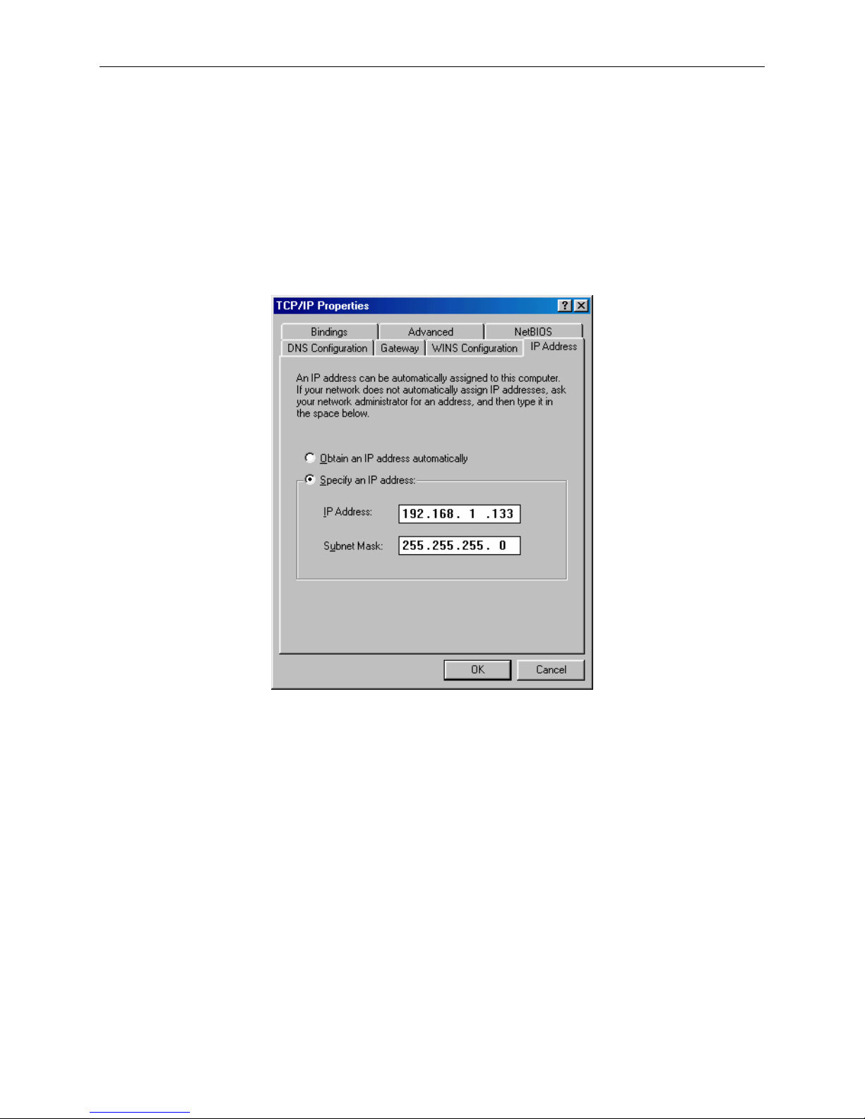
You can modify the IP address of your PC by from its TCP/IP definition. Follow the steps
below:
STEP 1: Enter the TCP/IP screen. (Under Windows XP, for example, click on Control Panel
from the Windows Start menu. Double-click on Network Connections.Right-click on
Local Area Connection and select Properties. Then select Internet Protocol and select
Properties.)
STEP 2: Change the IP address to the same domain as your endpoint (which has a default
address of 192.168.1.1 and a default subnet mask of 255.255.255.0). For example:
STEP 2: Click on OK to submit the settings.
1800-A2-GB20-00 11
Page 12

Command Line Interface User’s Guide
1.2 Login
To access Telnet to manage your endpoint, complete the following steps: The default IP address
is 192.168.1.1. Use the default IP address to log on to the endpoint if it was not changed.
STEP 1
STEP 2
STEP 3
STEP 4
STEP 5
Make sure that the endpoint and your PC are on the same network
segment.
Connect your endpoint to a PC via the LAN
Click RUN from Windows Start menu and type:
telnet x.x.x.x
(where x.x.x.x represents the IP address of the endpoint).
You will be prompted to enter a User Name and Password. Enter
root
for the User Name and
1234
for the Password.
The first prompt of the CLI interface appears. The prompt shows the
user name (ex. 1234) used to log to the endpoint.
login: root
Password:
[1234@ home]$
Note: If you fail to access the endpoint, make sure both your PC and th e endpoint are in the sam e IP
domain. If you do not know the e ndpoi nt’s IP ad dress, pr ess the re cessed b utton o n the rear
panel to restore the default L AN IP a ddress (192.168 .1.1).
12 1800-A2-GB20-00
Page 13

Command Line Interface User’s Guide
Chapter 2 General Operation
2.1 CLI Reference
All the system commands for various modules are organized in different directories. All these
directories are put under the directory called home. However, they can be listed using the ls
command. All the administration commands are put in home/auth. The current working
directory’s name is included in the command prompt (for example, [1234@bridge]$).
Each prompt consists of two parts: user name and directory. The two parts are divided by the
character @. For example, in the prompt 1234@bridge the first part (1234) is the user logged to
the endpoint. The second part (bridge) shows the current working directory.
The commands in the CLI are case sensitive.
1800-A2-GB20-00 13
Page 14

Command Line Interface User’s Guide
2.2 Generic
The CLI provides generic commands for navigating between directories, listing the commands in
a directory, and providing help. All the generic commands can be executed from any directory.
2.2.1 ls
ls
When you enter a directory, you can use the ls command to display the available commands. It
lists all the commands registered in the current working directory.
EXAMPLE
[1234 @ ethernet]$ ls
A <CMD> setemac
A <CMD> rmon
A <CMD> pread
A <CMD> pwrite
A <CMD> elink
A <CMD> up
A <CMD> down
A <CMD> stat
[1234 @ ethernet]$
2.2.2 help
The help command is useful when you are not sure of the functions and usages of a command. It
displays help and usage text for the specified command. If nothing is specified, it displays help
text for all general commands.
The following line is an example usage of the help command you type at the home prompt.
[1234 @ home]$ help –o <command>
EXAMPLE
14 1800-A2-GB20-00
Page 15

Command Line Interface User’s Guide
The following screen is an example of displaying the usage for the rip command.
[1234 @ home]$ help -o rip
DESCRIPTION
Contains RIP related commands
USAGE
rip
If nothing is specified, it displays information about all general commands.
2.2.3 accountstats
accountstats modulename
This command displays accounting details of the specified module.
2.2.4 exit
exit
If the user is working in the home directory, the session is closed. Otherwise exit changes the
working directory to its immediate parent directory.
2.2.5 version
version
This command displays the endpoint software version.
EXAMPLE
[1234 @ home]$ version
WLAN Gateway SoftwareV1.6.9
1800-A2-GB20-00 15
Page 16

Command Line Interface User’s Guide
2.2.6 date
date
This command displays the endpoint date and time.
EXAMPLE
[1234 @ home]$ date
DATE (MM:DD:YYYY) 1:10:2002 TIME (H:M:S) 4:56:59
2.2.7 erase
erase
This command erases all the configurations in the system. That means the factory default settings
are retrieved.
2.2.8 save
save
This command saves the current configurations into flash memory. The current configurations
will be available after the system is booted or reset.
2.2.9 reboot
reboot
This command restarts the endpoint. You must reconnect to the endpoint after you run this
command. The endpoint will be rebooted with the saved configurations on the flash. If you
reboot the endpoint without saving the changes, those parameters will be lost.
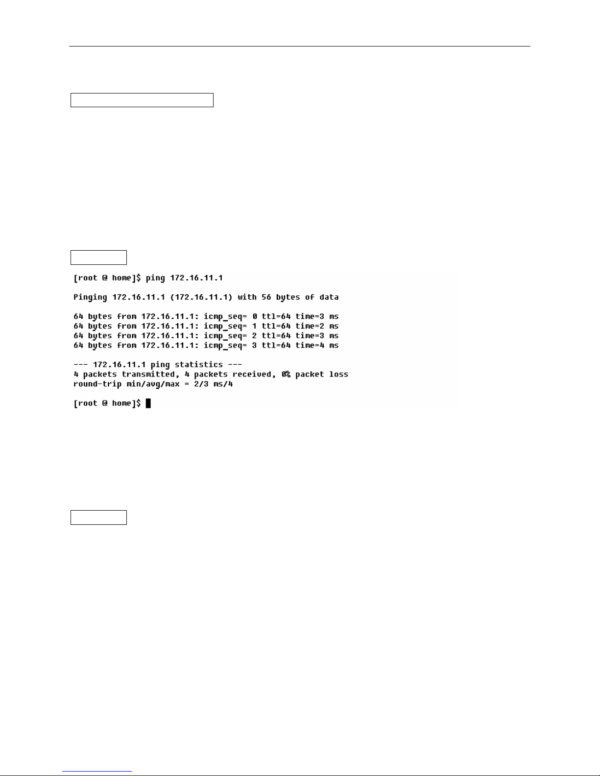
2.2.10 ping
ping address [ -o [ -s size ] ]
The utility ping utilizes the ICMP protocol's ECHO_REQUEST datagram to elicit an ICMP
ECHO_RESPONSE from the specified host or network gateway. If the host responds, ping will
print the response. By default, the ping command will send four ping requests to the host. This
diagnostic function can verify if the remote host is reachable for Telnet or FTP purposes.
If data size is not specified in the command, it will try 64 bytes for four times.
16 1800-A2-GB20-00
Page 17
Command Line Interface User’s Guide
COMMAND DESCRIPTION
address
destination IP address you wish to ping in the form x.x.x.x, where each x is a decimal number 0
to 255.
size
Data size to ping the host. The accepted size is 56 bytes to 1492 bytes.
EXAMPLE
2.2.11 time
time
The time command reveals the elapsed time of how long the endpoint is powered on.
EXAMPLE
[1234 @ home]$ time
System Elapse Time : 23:21:46:
[1234 @ home]$
1800-A2-GB20-00 17
Page 18

Command Line Interface User’s Guide
2.3 logger
logseverity
log
logftpserver
loginfo
logadd
2.3.1 logSeverity
logseverity -o error/info on/off
This command is used to set the trace for the log severity level.
COMMAND DESCRIPTION
error/info
This option specifies the severity level.
on/off
This option specifies weather the trace is set or not.
EXAMPLE
logseverity -o error on
This command will set the trace for the log level “error”.
logSeverity -o [error/info] [on/off ]
This command is used to set the specified log level as ON or OFF. By default, error and info log
level messages are off. There is no on/off option for exception log level messages. The exception
log messages are always displayed (on).
2.3.2 log
log -o [ [all] / [<modulename>] [<loglevel>]]
This command is used to display the logged messages. The logged messages will be displayed
based on the specified module name or the log level or both the module and log levels.
COMMAND DESCRIPTION
<loglevel>
18 1800-A2-GB20-00
Page 19

Command Line Interface User’s Guide
Loglevel can be given as exception, error or info.
<module name>
Module name can be all, ip, tcp, udp, sockets, rawip, icmp, arp, igmp, app, cdcli, if, telnet, dns,
snmp, http, ping, ftp, ftpd, tftp, bootp, dhcpc, dhcps, qosbw, ipsec, ike, nat, firewall, diffserv,
logger, queuing, ipoa, pppoa, ethoa, httpproxy, ftpproxy.
EXAMPLE
log –o all
This command will displays all the logged messages.
log –o firewall
This command will display messages logged from the firewall module.
log –o error
This command will display messages logged based on the log level “error”.
log –o firewall error
This command will display the messages logged based on the log level “error” from the firewall
module.
2.3.3 logFtpServer
logFtpServer [server_address] [username] [password]
This command is used to configure the ftp server address, user login and password to store the
logger messages.
EXAMPLE
logftpserver 192.168.1.100 snaidu 12345
This command will configure the ftp server address as 192.168.1.100, username as snaidu and
password as 12345. While uploading the logged messages it opens a connection to the ftp server
on 192.168.1.100 and login as “snaidu”. Then it will store the log messages in the file named
“fwlogfile”.
2.3.4 loginfo
loginfo
1800-A2-GB20-00 19
Page 20

Command Line Interface User’s Guide
This command displays the configured logger information. This will contain the trace
information, ftpserver, and login information.
EXAMPLE
[1234 @ logger]$ loginfo
Error Trace : OFF
Info Trace : OFF
Server Address : 192.168.26.10
User Name : firewall
Password : firewall
2.4 User Account
A default user account is provided to configure, maintain, and operate the endpoint in HTTP
(web), CLI, and FTP modes. The default user name is 1234, and the default password 1234. To
add, modify, delete, or list the user name and password, enter the auth directory.
[1234 @ home]$ auth
At the auth directory, you can use the ‘ls’ command to display the available commands:
[1234 @ home]$ auth
[1234 @ auth]$ ls
A <CMD> adduser
A <CMD> deluser
A <CMD> changepasswd
A <CMD> modifyuser
A <CMD> listusers
A <CMD> resetuser
[1234 @ auth]$
There are three management modes and two access privileges. The three modes are cli, http, and
ftp. The cli and http modes provide full parameters to configure, maintain, operate, and monitor
the endpoint. The ftp mode only allows software upgrade, configuration upgrade, and
configuration backup.
20 1800-A2-GB20-00
Page 21

Command Line Interface User’s Guide
The two access privileges are admin and ordin. The admin privilege provides full right including
read and write accesses. The ordin privilege only allows reading and monitoring the parameters
via http or cli. An ftp user must have an admin privilege.
adduser
adduser username -o -services [services] -permissions [permissions]
services : [cli/ftp/http]
permissions : [admin/ordin]
Adds a new user to the system. This command asks to set password for the user. Only
administrators can use this command.
EXAMPLE
[1234 @ auth]$ adduser mrpizza -o -services cli -permissions ordin
Enter password:
Confirm password:
User Name Succesfully Added.
[1234 @ auth]$
deluser
Deluser <username>
Enter this command followed by the name of the user to be deleted. Only administrators can use
this command.
EXAMPLE
[1234 @ auth]$ deluser mrpizza
Successfully Deleted
[1234 @ auth]$
modifyuser
modifyuser <username> -o
-addservices <cli | ftp | http>
-delservices <cli | ftp | http>
-permissions <admin | ordin>
The modifyuser command modifies the properties of a user’s account.
1800-A2-GB20-00 21
Page 22

Command Line Interface User’s Guide
COMMAND DESCRIPTION
<username>
The name of the user whose services or permissions are to be modified.
EXAMPLE
-addservices <cli | ftp | http>
Adds cli, ftp, or http services to the user.
-delservices <cli | ftp | http>
Removes cli, ftp, or http services from the user.
modifyuser xyz –o -addservices ftp -permissions ordin
Allows user “xyz” ordinary permissions to access the system via ftp. In addition, gives the user
“xyz” ordinary permissions. In other words user “xyz” is not an administrator.
modifyuser abc -o -delservices http
Prohibits user “abc” from accessing the system via http.
modifyuser xyz -o -addservices ftp delservices http -permissions ordin
Allows user “xyz” to access the system via ftp and prohibits that user from accessing the system
via http. In addition, gives the user “xyz” ordinary permissions. In other words user “xyz” is not
an administrator.
changepasswd
changepasswd <username>
Changes password of the existing user. This is an administrators command; ordinary users can
not use this. This command prompts for entering the old password before setting up the new
password.
EXAMPLE
[1234 @ auth]$ changepasswd
changepasswd username
[1234 @ auth]$ changepasswd pppoe
Enter old password:
Enter New password:
Confirm New password:
Password changed
[1234 @ auth]$
The command changes the password for user “pppoe.”
22 1800-A2-GB20-00
Page 23

Command Line Interface User’s Guide
listusers
listusers
The listusers command lists all registered users to use cli/http/ftp.
EXAMPLE
[1234 @ auth]$ listusers
1 1234 cli http ftp ADMIN
2 pppoe http ADMIN
3 maylyne ORDIN
4 may ORDIN
5 pizza cli ftp ADMIN
[1234 @ auth]$
resetuser
The resetuser command resets the user password. This is an administrators command; ordinary
users can not use this. This command won’t prompt for inputting the old password while
command “changepasswd” will.
EXAMPLE
[1234 @ auth]$ resetuser pppoe
Enter New password:
Confirm New password:
Password changed
[1234 @ auth]$
Resets the password for user “pppoe.”
2.5 Ethernet IP Address
There are two configurable Ethernet interfaces, identified with eth0 and eth1 in CLI. Each
Ethernet interface provides two default IP addresses.
z Interface eth0- 192.168.1.1 (primary) and 192.168.1.2 (alias)
z Interface eth1- 192.168.2.1 (primary) and 192.168.2.2 (alias)
1800-A2-GB20-00 23
Page 24

Command Line Interface User’s Guide
To set up an IP address and subnet mask for the Ethernet interface, use the following command
after the prompt of [1234 @ home]$.
ifconfig -o <interface-name> inet <address> [parameters]
ifconfig -o -a displays the information of the interfaces
ifconfig -o -l
parameters- mtu <n 72-1500>, broadcast <address>, netmask <mask>, up, down
COMMAND DESCRIPTION
<interface name>
The LAN interface to be configured. Type eth0 for Interface Ethernet 1, and type eth0 for
Interface Ethernet 2.
<address>
The IP address or subnet mask to be assigned to the interface. Dot-notation is used to enter the IP
address (for example 192.168.2.1).
netmask <mask>
The netmask is used to extract the network portion of the IP address. It also specifies how much
of the IP address is to be reserved for subdividing the network into sub networks, which are
taken from the host field of the address. Netmask is added with the interface IP address to get a
network ID that is used in routing to indicate that this network is reachable through these
interfaces. The mask can be specified as a single hexadecimal number with a leading 0x for
example 0xffffff00, or with a dot-notation Internet address 255.255.255.0
alias <address>
To add the alias IP address
-alias <address>
To delete the alias IP address
2.5.1 Primary IP address
To assign an IP address of 172.0.0.1 with a 24-bit subnet mask to the eth1 interface, use this
command:
ifconfig eth1 172.0.0.1 netmask 255.255.255.0
After typing the command, the home prompt displays. Save the changes by typing save. The
following message displays and shows that the changes are successful.
Configuration saved successfully
24 1800-A2-GB20-00
Page 25

Command Line Interface User’s Guide
2.5.2 Alias IP Address
To set up the alias IP address, use this command:
[1234 @ home]$ ifconfig –o <interface name> inet <address> alias netmask <address>
EXAMPLE
[1234 @ home]$ ifconfig -o eth0 inet 172.1.1.1 alias netmask 255.255.255.0
The above example assigns an alias IP address of 172.1.1.1 with a 24-bit subnet mask to the eth0
interface.
[1234 @ home]$ ifconfig -o <interface name> inet <address> -alias netmask <address>
To delete the alias IP address, use this command:
2.6 Rarpd
add
list
rarpd
delete
The rarpd commands are put in the rarpd directory, used to get the IP address of diskless system.
2.6.1 add
add <0xH/Waddress > <IPAddress >
Used to add Hardware address and IP address into the DataBase.
COMMAND DESCRIPTION
<0xH/Waddress >
Hardware address in hexadecimal format.
<IPAddress >
IP address in dot notation.
1800-A2-GB20-00 25
Page 26

Command Line Interface User’s Guide
EXAMPLE
add 0x112233445566 192.168.3.4
Adds the H/W address and IP Address mapping in the database.
2.6.2 delete
delete <0xH/Waddress >
Deletes an entry in the existing RARP DataBase.
<0xH/Waddress >
Hardware address in hexadecimal format.
EXAMPLE
delete 0x112233445566
Deletes mapping of H/W address 11:22:33:44:55:66 to IP Address, from the database.
2.6.3 list
list
Lists the RARP DataBase entries.
EXAMPLE
[1234 @ rarpd]$ list
H/W ADDR IP ADDRESS
11:22:33:44:55:66 192.168.3.4
26 1800-A2-GB20-00
Page 27

Command Line Interface User’s Guide
2.6.4 rarpd
rarpd <-a | interface>
The rarpd command starts the RARPD on the specified interface or all the interfaces.
EXAMPLE
rarpd eth0
This command starts the RARPD on eth0 interface.
rarpd eth0
If RARPD is already running the above command, it displays: “Rarpd is already running on the
interface”
rarpd -a
This command starts the RARPD on all the interfaces.
2.7 timeout
timeout -t(telnet) n(seconds)
The timeout command sets up the timeout period for the telnet session
COMMAND DESCRIPTION
<seconds>
the timeout period in seconds, which can be up to 300 seconds.
EXAMPLE
timeout -t 300
The command configures the timeout period to 300 seconds.
2.8 baudrate
baudrate <value>
1800-A2-GB20-00 27
Page 28

Command Line Interface User’s Guide
COMMAND DESCRIPTION
<value>
The baud rate of the console session. 0 represents 9600 bps; 1 represents 38400 bps; 2 represents
57600 bps. 3 represents 115200 bps.
EXAMPLE
baudrate 3
The baudrate command configures the baud rate to 115200 bps.
28 1800-A2-GB20-00
Page 29
Command Line Interface User’s Guide
Chapter 3 Quick Configuration
This chapter describes how to configure the endpoint for the first time using the CLI. The
endpoint can work after these settings are complete.
3.1 RFC 1483 Bridged
To enable the bridging function of the endpoint, enter the sndcp directory from the prompt of
[1234 @ sndcp]$. In the sndcp directory, type bridge to enter the bridge directory.
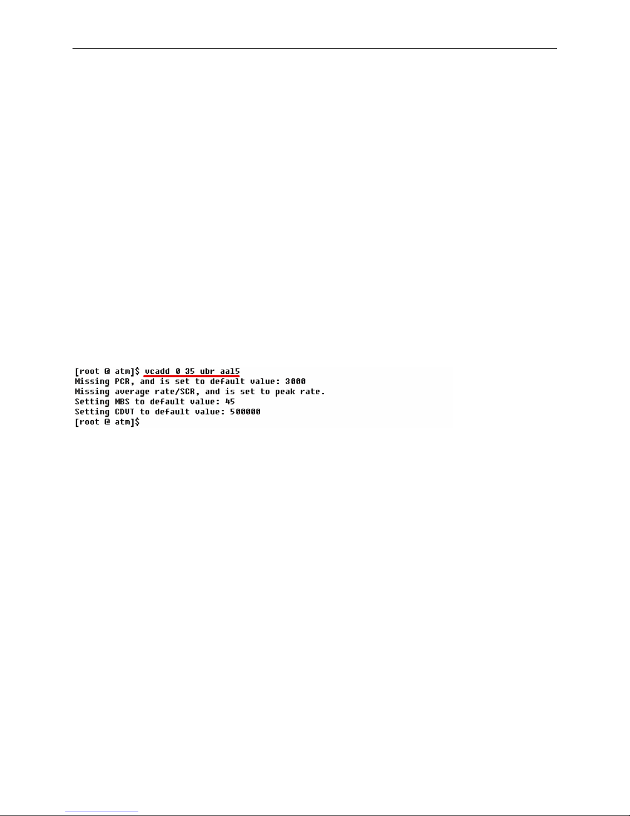
3.1.1 PART 1 Create a PVC
1. Type atm at the home prompt to enter the atm directory.
2. Type vcadd 0 35 ubr aal5
3. At the atm prompt, type home or exit to return to the home prompt.
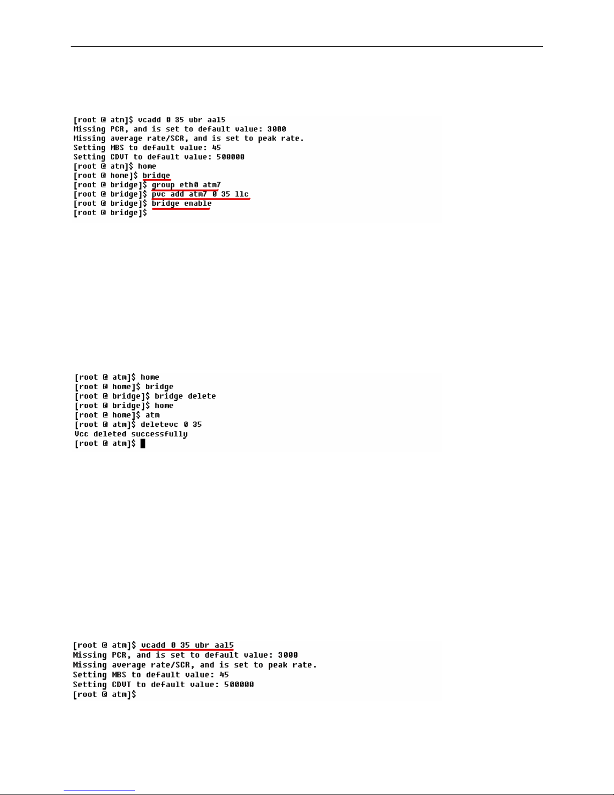
3.1.2 PART 2 Set the PVC to RFC 1483 Bridged
1. If there is no other RFC 1483 PVC set up, you must join the Ethernet interface to an ATM
interface (atm0 to atm7). Therefore, traffic can be transferred between the two interfaces. To
do this, type bridge to enter the bridge prompt. By factory default, interfaces Ethernet, atm7,
and wlan0 are joined to the bridge.
2. Type group eth0 atm7. In this case, atm7 is used. You can choose any other atm interface
you wish.
3. If the setup is successful, the bridge prompt pops up. If a PVC was set up other than the new
one, the message pops up: Group Exist or Interface Busy
You must delete the old PVC or PVCs to add the new group.
4. Under the bridge prompt, type pvc add atm7 0 35 llc. In this case, atm7 is used. You must
choose the atm interface that is joined to the bridge.
1800-A2-GB20-00 29
Page 30
Command Line Interface User’s Guide
5. Type bridge enable.
6. If the bridge prompt pops up, a PVC 0/35 is successfully enabled for the RFC 1483 Bridged
mode.
3.1.3 PART 3 Delete the PVC for RFC1483 Bridged
To delete the PVC set up for the RFC 1483 Bridged, you must delete the service first under the
bridge prompt. Secondly, delete the VC under the atm prompt. The following screen is an
example.
3.2 RFC 1483 Routed
There are two major parts to set up a RFC 1483 Bridged PVC. The first part is to add a PVC
under the atm directory. The second part is to assign the new PVC to the RFC1483 Bridged
mode under the bridge directory. The following is an example of adding an RFC1483 Bridged
PVC at 0/35.
3.2.1 PART 1 Create a new VC
1. Type atm to enter the home prompt.
2. Type vcadd 0 35 ubr aal5
30 1800-A2-GB20-00
Page 31

Command Line Interface User’s Guide
3. At the atm prompt, type home or exit to return to the home prompt.
3.2.2 PART 2 Set the PVC to RFC 1483 Routed
1. Return to the home prompt.
2. Type sndcp to enter the sndcp prompt.
3. Type routedbridge atm0 enable 0 35 -o -enc LLC. In this case, atm0 is used. You can
choose other atm interface if you wish. In addition, in the command, LLC must be
capitalized.
4. If the sndcp prompt pops up, a PVC 0/35 is successfully created for RFC 1483 Routed mode.
3.2.3 PART 3 Set up an IP address for the WAN interface
1. Return to the home prompt and type the following command.
If you need the usage of the ifconfig command, type ifconfig.
2. If the Ethernet IP address is successfully set up, the home prompt pops up.
3.2.4 PART 4 Delete the PVC to RFC 1483 Routed
To delete the PVC set up for the RFC 1483 Routed, you must disable the service first under the
sndcp directory. Secondly, delete the VC under the atm directory. The following screen is an
example.
1800-A2-GB20-00 31
Page 32

Command Line Interface User’s Guide
3.3 IPoA
3.3.1 PART 1 create a new PVC
1. Type atm at the home prompt to enter the atm directory.
2. Type vcadd 0 35 ubr aal5
3. At the atm directory, type home or exit to return to the home prompt.
3.3.2 PART 2 Set the PVC to IPoA
1. Return to the home prompt.
2. Type sndcp to enter the sndcp directory.
3. Type ipoa to display the command usage to set up an ipoa entry. The command usage is
shown below.
EXAMPLE
32 1800-A2-GB20-00
Page 33

Command Line Interface User’s Guide
4. If the sndcp prompt pops up, a PVC 0/35 is successfully created for the IPoA mode.
3.3.3 PART 3 Delete the PVC for IPoA
To delete the PVC set up for IPoA, you must delete the profile first under the sndcp prompt.
Secondly, delete the VC under the atm prompt. The following screen is an example.
3.4 PPPoE
3.4.1 PART 1 Create a new VC
1. Type atm at the home prompt to enter the atm directory.
2. Type vcadd 0 35 ubr aal5
3. At the atm prompt, type home or exit to return to the home prompt.
3.4.2 PART 2 Set the PVC to PPPoE
1. Return to the home prompt.
2. Type sndcp to enter the sndcp prompt.
3. Type pppoe to display the command usage to set up a PPPoE entry. The command is shown
below.
1800-A2-GB20-00 33
Page 34

Command Line Interface User’s Guide
The pppoe command covers the settings for the PPPoE entry number, encapsulation type,
timeout period, authentication, user name, password, VPI, VCI, and NAT. You can complete a
PPPoE entry by typing this command that covers these basic settings. If you need a complete
setting, refer to the usage instruction above.
4. If the sndcp prompt pops up, a PVC 0/35 is successfully created for PPPoE mode.
3.4.3 PART 3 Delete the PVC for PPPoE
To delete the PVC set up for the PPPoE, you must delete the profile first under the sndcp prompt.
Secondly, delete the VC under the atm prompt. The following screen is an example.
34 1800-A2-GB20-00
Page 35

Command Line Interface User’s Guide
3.5 PPPoA
3.5.1 PART 1 Create a new VC
1. Type atm to enter the atm directory.
2. Type vcadd 0 35 ubr aal5
3. At the atm prompt, type home or exit to return to the home prompt.
.
3.5.2 PART 2 Set the PVC to PPPoA
1. Return to the home prompt.
2. Type sndcp at the home prompt to enter the sndcp prompt.
3. Type PPPoA to display the command to set up a PPPoA entry. The command usage is
shown below.
1800-A2-GB20-00 35
Page 36

Command Line Interface User’s Guide
The pppoa command covers the basic settings for the PPPoA profile number, encapsulation
type, timeout period, authentication, user name, password, VPI, VCI, and NAT. You can
complete a PPPoA entry by typing this command that covers these basic settings. If you need a
complete setting, refer to the usage instruction above.
4. If the sndcp prompt pops up, a PVC 0/35 is successfully created for PPPoA mode.
3.5.3 PART 3 Delete the PVC for PPPoA
To delete the PVC set up for the PPPoA, you must delete the profile first under the sndcp
prompt. Secondly, delete the VC under the atm prompt. The following screen is an example.
3.6 MER
3.6.1 PART 1 Create a new VC
1. Type atm to enter the home prompt.
2. Type vcadd 0 35 ubr aal5
3. At the atm prompt, type home or exit to return to the home prompt.
3.6.2 PART 2 Set the PVC to MER
1. Return to the home prompt.
2. Type sndcp at the home prompt to enter the sndcp prompt.
36 1800-A2-GB20-00
Page 37

Command Line Interface User’s Guide
3. Type 1483mer to display the command to set up an MER entry. The command usage is
shown below. For the port parameter specified in the command, always type mer0. Only one
MER entry can be created.
EXAMPLE
4. If the sndcp prompt pops up, a PVC 0/35 is successfully created for MER mode.
3.6.3 PART 3 Set up an IP address for the WAN interface
1. Return to the home prompt and type the following command.
If you need the usage of the ifconfig command, type ifconfig.
2. If the WAN IP address is successfully set up, the home prompt pops up.
3.6.4 PART 4 Delete the PVC for MER
To delete the PVC set up for the MER, you must delete the profile first under the sndcp prompt.
Secondly, delete the VC under the atm prompt. The following screen is an example.
1800-A2-GB20-00 37
Page 38

Command Line Interface User’s Guide
Chapter 4 Command Line Interface SIP
SIP Configuration
4.1 SIP Host (User Agent)
4.1.1 Configuration
Command syntax:
confighost <Interface> -o [-up <useproxy(yes/no)>]
Usages:
This command configures binding interface and proxy info for Host.
Description:
Interface: Binding interface of SIP User-Agent
useproxy: Option of Using Proxy/Registrar server if it is configured.
Example:
confighost eth0
confighost eth0 –o –up yes
4.1.2 Displaying
Command syntax:
listhost
Usages:
Display the Configured Host information.
Example:
####HostINFO####
Interface Port Transport UseProxy MaxDigits
------------------------------------------------eth0 5060 UDP NO 14
38 1800-A2-GB20-00
Page 39

Command Line Interface User’s Guide
4.2 SIP Proxy/Registrar Server
4.2.1 Configuration
Command syntax:
configproxyreg <proxy/register Addr> -o [-p <proxy/register
Port>]
Usages:
This command configures the Proxy/Registrar Server host address and Port
Number.
Description:
Address: Ip Address or FQDN of outbound SIP-Proxy/Registrar server .
Port: Port Number of SIP-Proxy server where it will Receive all the SIP
messages.
Default Port Number is 5060.
Example:
configproxyreg 192.168.1.254
configproxyreg 192.168.1.254 -o -p 5060
4.2.2 Displaying
Command syntax:
listproxyreg
Usages:
Display the Configured Proxy/Registrar Server information.
4.3 SIP Domain
4.3.1 Configuration
Command syntax:
configdomain <Domain>
Usages:
1800-A2-GB20-00 39
Page 40

Command Line Interface User’s Guide
This command configures the Domain.
Description:
Domain: Configured domain.
Example:
configdomain paradyne.com
4.3.2 Displaying
Command syntax:
listdomain
Usages:
Display the Configured Domain information.
Example:
#### Domain LIST ####
Domain
-------------------- paradyne.com
4.4 Codecs Supported
4.4.1 Configuration
Command syntax:
configcodecs -o [PCMU] [PCMA] [G729]
Usages:
This command configures Codecs to be supported for the configured User-
Agent.
Description:
PCMU, PCMA, G729 : Name of the Codecs
Example:
configcodecs –o PCMU PCMA G729
40 1800-A2-GB20-00
Page 41

Command Line Interface User’s Guide
4.4.2 Displaying
Command syntax:
listcodecs
Usages:
Displays all the Configured Codecs.
Example:
#### CODECS INFO ####
PCMU PCMA G729
--------------------on on on
4.5 Phone
4.5.1 Configuration
Command syntax:
configphone <portNumber> <phoneUserName> -o [-d<DispName>]
[-e<expires>] [-q<qvalue>] [-c<PreferCodec>]
Usages:
This command Configures sip parameter required to build SIP messages for
phone(s) attached to SIP UA to send signaling information to peer.
Description:
portNumber: port number of the SIP UA to which Phone is attached.
Presently Valid values are 1or 2.
phoneUserName: Name of the User who is using the phone connected to
above portNumber.
phoneDisplayName:
Display Name of the above user.
expires: Time period for registering to Registrar/ProxyServer.
PreferCodec: preferred codec of this user.
Qvalue: Preference for the phone registered to proxy/registrar.
Example:
configphone 1 600 -o -c PCMU
1800-A2-GB20-00 41
Page 42

Command Line Interface User’s Guide
4.5.2 Displaying
Command syntax:
listphones
Usages:
Display the Configured sip parameters of all the configured phones.
Example:
#### PHONELIST ####
port User DispName Expires QValue Codec Frame CallerID DTMF
--------------------------------------------------------------------------- 1 600 600 120 0.8 PCMU 20 ENABLE
Buddy List (List of remote user(s) one wish to call, only works when not using proxy)
4.5.3 Configuration
Command syntax:
addbuddy <speeddial> <userName> <destIPAddr> -o [-d<displayName>] [-p<destPort>]
Usages:
The BUDDY LIST is used to setup SIP URI of the parties that one wish to call.
Description:
speeddial: is speedDial number which maps to remote party SIP-URI after
dialing on key/phone pad.This should be unique for different SIP-URI.
userName: Name of the remote User who is to be contacted.
destIPAddr: is the IP address of the party one wish to call.
displayName: Display Name of the above remote user.
destPort: Port Number of Remote User-Agent where it will Receive
all the SIP messages.Default Port Number is 5060.
Example:
addbuddy 1234 5551234 192.168.1.2
42 1800-A2-GB20-00
Page 43

Command Line Interface User’s Guide
4.5.4 Displaying
Command syntax:
listbuddy
Usages:
List all the Configur ed buddy with their information .
Example:
#### BUDDYLIST####
Index Name Host Dial Port DispName
-------------------------------------------------1 5551234 192.168.1.2 1234 5060 5551234
4.5.5 Deleting
Command syntax:
deletebuddy <index>
Usages:
Delete the Configured buddy information in the Buddy List according the specified
index.
Example:
deletebuddy 1
4.6 Call forward
4.6.1 Configuration
Command syntax:
configcf <portnumber> <username> <Host Ipaddr>
Usages:
The configcf command is used to configure the call forward information for the
particular phone.
Description:
portnumber: phone port number for which the configuration will be done.
1800-A2-GB20-00 43
Presently Valid values are 1or 2.
Page 44

Command Line Interface User’s Guide
username: Sip User name of the forwarding address where the calls will
be forwarded.
Host Ipaddr: Sip host addr of the forwarding address where the calls will
be forwarded.
Example:
Configcf 1 102 192.168.1.102
Command syntax:
callforward <portnumber> -o [-cf <yes/n o>] [-u f <yes/no> ]
Usages:
To enable call forward to the given port only when the configuration is done.
Example:
callforward 1 -o -cf yes -uf yes
4.6.2 Displaying
Command syntax:
listcf
Usages:
List all the call forward information.
Example:
#### Call forward configuration ####
port Cf_flag Uf_Flag User_Name Host_Ipaddr NumRings
----------------------------------------------------------1 YES YES 102 192.168.1.102 5
4.7 Authentication
4.7.1 Configuration
Command syntax:
configauth <portNumber> <username> <password>
Usages:
44 1800-A2-GB20-00
Page 45

Command Line Interface User’s Guide
The configcf command is used to configure the authentication username and
password.
Description:
portnumber: phone port number for which the configuration will be done.
Presently Valid values are 1or 2.
username: Username for authentication.
password: Password for authentication.
Example:
configauth 1 123 abc
4.7.2 Displaying
Command syntax:
listauth
Usages:
Display the authentication information.
Example:
#### AUTHLIST####
--------------------------------1 123 abc
4.8 Registration
Command syntax:
register <PortNumber>
Usages:
send Register request to Registrar server and phone corresponding to the port
number is registered with proxy/registrar.
Description:
portNumber: port number of the Phone connected to SIP UA.
1800-A2-GB20-00 45
Page 46

Command Line Interface User’s Guide
Presently Valid values are 1or 2.
Example:
register 1
4.9 Inter-digit Timeout
Command syntax:
digitimeout <sec>
Usages:
Used to set inter digit timeout value.
Description:
sec: Inter digit timeout value, valued value are from 1 to 10, 0 to disable.
Example:
digitimeout 4
4.10 Max Rings
Command syntax:
maxrings <num>
Usages:
Used to set max ring numbers for call forward on no reply/answer.
Description:
num: Number of rings for activating CFNR.
Example:
maxrings 5
46 1800-A2-GB20-00
Page 47

Command Line Interface User’s Guide
4.11 Dial Plan
Command syntax:
dialplan -o list
dialplan -o add <dialnumber> <outnumber>
dialplan -o del <index>
Usages:
Used to configure dialplan for converting dialed digits to out-dialing digits.
Description:
dialnumber: User dialed digits.
outnumber: Out-dialing digits.
Example:
dialplan –o add xxxx 555xxxx
dialplan –o add 949xxxxxxx xxxxxxx
4.12 Voice Configuration
4.12.1 Voice Options
Command syntax:
voiceopt -o -vad <on/off> -plc <on/off> -ec <on/off> -t
<val>
Usages:
Configuring voice options parameters.
Description:
vad: Voice Active Detection.
plc: Packet Lose Concealment.
ec: Echo Cancellation
t: Echo Cancellation Tail Length
Example:
voiceopt -o -vad off -plc on -ec on -t 20
1800-A2-GB20-00 47
Page 48

Command Line Interface User’s Guide
4.12.2 Jitter Buffer Configuration
Command syntax:
jitter -o [-t <Type>] [-thr <Threshold>]
Usages:
Configuring jitter parameters.
Description:
Type: FJB or AJB.
Threshold: Thresold is only for Fixed Jitter Buffer scheme.
Example:
jitter -o -t FJB -thr 20
4.12.3 Country
Command syntax:
countryopt -o -c <country>
Usages:
Used to set/display country options.
Description:
country: Specifies the country.
AUSTRALIA, FRANCE, GERMANY, JAPAN, NETHERLANDS, SPAIN,
TAIWAN, USA
Example:
countryopt -o -c TAIWAN
4.13 Phone Operations
4.13.1 Normal Call Hold
This feature provides the user to suspend his conversation until he resumes it.
Pressing * key followed by 2 while talking enables this feature. No audio data flows
when a session is on hold.
48 1800-A2-GB20-00
Page 49

Command Line Interface User’s Guide
4.13.2 Consultation Call Hold
This feature enables the user to hold his conversation and allows making a new
connection (consulting connection) to another user. User by pressing * key followed
by 2(Normal Hold) and dialing a valid number after getting dial tone invokes
consultation.
4.13.3 Call Resume
This feature provides the user to Resume his conversation after it was hold.
Pressing * key followed by 3 enables this feature.
4.13.4 Call Switch
This feature allows user is to switch between the connections if there are 2 calls
active at one time. User by pressing * key followed by 2 then pressing * key followed
by 5 enables this feature.
4.13.5 Call Waiting
This feature provides user to switch and talk to two different remote users. User by
pressing * key followed by 2 after hearing intermittent call-waiting tone hold the
active call. Then pressing * key followed by 5 allow the waiting user to talk. Now user
can either terminate the by pressing * key followed by 9 or hold by pressing * key
followed by 2 current active call and switch to earlier call by pressing * key followed
by 5.
1800-A2-GB20-00 49
Page 50

Command Line Interface User’s Guide
Chapter 5 Advanced Configuration
5.1 Static Route
To set up the static route, type route at the prompt to display the static route commands. These
commands are used to add, delete, modify, and flush the static route table.
route add -o -dest {dest ip addr} -gateway {gateway ip addr} [{-option value}*]
route add -o -dest {dest ip addr} -interface {interface name} [{-option value }*]
route delete -o -dest {dest ip addr}
route change -o -dest {dest ip addr} -gateway {new ip addr}
route get -o -dest {ip addr}
route flush
options : mtu & hopcount &netmask
The command route add -o -dest {dest ip addr} -interface {interface name} [{-option value
}*] is reserved only.
EXAMPLE
50 1800-A2-GB20-00
Page 51

Command Line Interface User’s Guide
5.2 Ethernet
The ethernet command is used to configure the Ethernet interface parameters. Ethernet
commands are located in the “ethernet” directory.
setemac
rmon
pread
pwrite
elink
up
down
stat
5.2.1 MAC Address
setemac <xx:xx:xx:xx:xx:xx>
This sets up the MAC address. In order for the MAC changes to take effect, the configuration
must be saved (using ‘save’command in the home directory) and the system rebooted.
< xx:xx:xx:xx:xx:xx >
The MAC address in colon separated notation. Two hex digits must be supplied between the
colons. Twelve hex digits comprise a MAC address. (i.e. “aa:bb:cc:01:22:05”).
EXAMPLE
[1234 @ ethernet]$ setemac
setemac xx:xx:xx:xx:xx:xx
[1234 @ ethernet]$ setemac 11:01:0b:ab:00:00
Base MAC address updated. Don't forget to SAVE it
[1234 @ ethernet]$home
[1234 @ home]$save
1800-A2-GB20-00 51
Page 52

Command Line Interface User’s Guide
5.2.2 rmon
This command reads the MAC RMON counters. Type rmon eth0 at the prompt to collect the
Ethernet interface statistics.
5.2.3 pread
pread <interface> <port(decimal)>
Reads PHY register
EXAMPLE
[1234 @ ethernet]$ pread eth0 1
Register 1 value 0xffff
Displays the register 1 value of eth0 interface.
5.2.4 pwrite
[1234 @ ethernet]$ pwrite <interface> <port(decimal)> <value(hex)>
Writes PHY register
52 1800-A2-GB20-00
Page 53

Command Line Interface User’s Guide
5.2.5 elink
elink <interface> -o [[auto] | [10 | 100 | auto_speed ] | [half | full | auto_duplex]
The elink command configures the speed and/or duplex of the Ethernet interface. The default
setting is auto for auto negotiation. With auto negotiation, both the speed and duplex are
configured based upon what the link is connected to. It is also possible to configure the duplex,
say half and full, and specify auto_speed so that only the speed is auto negotiated. Similarly for
auto_duplex.
COMMAND DESCRIPTION
<interface>
The name of the Ethernet interface. This is eth0.
Auto
This specifies that both the speed and duplex are auto negotiated.
10
This specifies that the speed is set to 10M bits per second.
100
This specifies that the speed is set to 100M bits per second.
auto_speed
This specifies that the speed is auto negotiated.
half
This specifies half duplex
full
This specifies full duplex
auto_duplex
This specifies that the duplex is auto negotiated.
EXAMPLE
[1234 @ ethernet]$ elink eth0 -o 10 half
This command sets the Ethernet to a speed of 10Mbps half duplex.
[1234 @ ethernet]$ elink eth0 -o auto_speed full
The speed will be auto negotiated and the link will use full
1800-A2-GB20-00 53
Page 54

Command Line Interface User’s Guide
5.2.6 Ethernet up/down
The default setting of the Ethernet function is enabled. To disable it, use the down eth0
command. To enable it, use the up eth0 command. When the Ethernet interface is disabled, the
telnet or web session will be terminated. The endpoint can be only accessible from the console
port.
5.3 Bridge
The bridge commands sets up the bridge functions, covering the following commands. They are
located in the “bridge” directory.
arpproxy
pvc
group
group3
cachetimer
setmultiport
list
stats
bridge
vstats
vlantable
vlanmode
fdbmode
igmpsnooping
stp
filter
filterlist
filterflush
l2_list
l2_fil
5.3.1 arpproxy
arpproxy [on/off]
The arpproxy command enables or disables the ARP (Address Resolution Protocol) proxy (L3
bridging)
COMMAND DESCRIPTION
on
This enables the ARP proxy
54 1800-A2-GB20-00
Page 55

Command Line Interface User’s Guide
off
This disables the ARP proxy
5.3.2 pvc
pvc add/delete port vpi vci encapsulation -o <-vpn OUI vpnId>
The pvc command attaches a PVC to the WAN interface.
COMMAND DESCRIPTION
add
This adds the specified PVC to the bridge.
delete
This deletes the specified PVC to the bridge.
<port>
A string identifying the wan interfaces e.g. atm0.
<vpi> <vci>
Virtual Path Identifier and Virtual Circuit Identifier for the ATM connection.
<encapsulation>
This specifies the encapsulation type. The possible values are llc or vc which represent Logical
Link Control or VC multiplexing respectively.
- vpn OUI vpnId
Enable VPN Encapsulation on this interface. The OUI (Organizationally Unique Identifier) and
VPN identifier are specified as numbers.
5.3.3 group
group if if
group if if –o if
The group command assigns or groups two interfaces or three interfaces to the bridge. To group
two interfaces, use the command:
group if if
To group three interfaces, use the command
group if if –o if
1800-A2-GB20-00 55
Page 56

Command Line Interface User’s Guide
If the bridge group was already set up, to configure the new group, delete the previous group by
using the bridge delete command, and then group the new interfaces you wish to the bridge.
The group and group3 commands are similar functions, but they group different number of
interfaces to the bridge.
COMMAND DESCRIPTION
interface_name
The name of an interface e.g. eth0, atm0… atm1 etc.
EXAMPLE
group eth0 atm0
The interfaces eth0 and atm0 are assigned to the bridge.
group eth0 atm0 –o atm1
The interfaces eth0, atm0, and atm1 are assigned to the bridge.
[1234 @ bridge]$ group eth0 atm1
Group Exist or Interface Busy
[1234 @ bridge]$ bridge delete
[1234 @ bridge]$ group eth0 atm0
[1234 @ bridge]$
Bridge group already exists. You must delete the group and then assign interfaces eth0 and atm0
to the bridge.
5.3.4 group3
group if if if
group if if if –o if
The group command assigns or groups three interfaces or four interfaces to the bridge. To group
three interfaces, use the command:
group if if
To group four interfaces, use the command
group if if –o if
56 1800-A2-GB20-00
Page 57

Command Line Interface User’s Guide
If the bridge group was already set up, to configure the new group, delete the previous group by
using the bridge delete command, and then group the new interfaces you wish to the bridge.
COMMAND DESCRIPTION
interface_name
The name of an interface e.g. eth0, atm0… atm1 etc.
EXAMPLE
group eth0 atm0 atm4
The interfaces eth0, atm0, and atm4 are assigned to the bridge.
group eth0 atm0 atm2 atm4–o atm5
The interfaces eth0, atm0, atm2, atm4, and atm5 are assigned to the bridge.
[1234 @ bridge]$ group3 eth0 atm1 atm2
Group Exist or Interface Busy
[1234 @ bridge]$ bridge delete
[1234 @ bridge]$ group eth0 atm1 atm3
[1234 @ bridge]$
Bridge group already exists. Delete the group and then assign interfaces eth0, atm1, and atm3 to
the bridge.
5.3.5 cachetimer
cachetimer <timeout>
Specifies the idle timeout for bridge table entries. The timeout value is in seconds. Whenever
there is any traffic passing through bridge, bridge will maintain the lookup table with the MAC
addresses coming from configured interface( through LAN). If the traffic is destined to any
MAC address which is found in the lookup table, that packet is not sent to the ATM interface. If
there is no traffic from particular machine for certain time period then that entry is deleted from
the lookup table. The time that the bridge will clear the bridge lookup entry is the cachetimer
timeout.
5.3.6 setmultiport
setmultiport enable | disable
Enables or disables flooding between ATM PVCs.
1800-A2-GB20-00 57
Page 58

Command Line Interface User’s Guide
5.3.7 list
list
Lists bridge parameters.
EXAMPLE
5.3.8 stats
stats
Displays bridge statistics.
EXAMPLE
5.3.9 bridge
bridge enable | disable | delete
Enables, disables, or deletes the configuration of the bridge.
5.3.10 vstats
vstats
lists the VLAN groups.
58 1800-A2-GB20-00
Page 59

Command Line Interface User’s Guide
5.3.11 vlantable
vlantable groupNumber(0 - 3) -o ethernetPort(1 - 4) -atm vci vpi
configures the VLAN groups. Up to four groups (0-3) can be set up, and four Ethernet ports (0-
3) can be joined to these groups.
COMMAND DESCRIPTION
groupNumber(0 - 3)
There are four groups. Use the number (0-3) to represent each group.
ethernetPort[0] -> Link4
ethernetPort[1] -> Link3
ethernetPort[2] -> Link2
ethernetPort[3] -> Link1
ethernetPort(0 - 3)
Each LAN interface can only be attached to one VLAN.
0- Ethernet port 1
1- Ethernet port 2
2- Ethernet port 3
3- Ethernet port 4
vci vpi
Type the VCI/VPI value for the VLAN. You can only select from values that have been
configured as Bridge mode on the WAN interface.
EXAMPLE
vlantable 0 -o 0 1 2 3 -atm 0 33
5.3.12 vlanmode
vlanmode [on/off]
Enables or disables VLAN. After VLAN is enabled, also configure it’s functions like fdbmode,
igmpsnooping, and
COMMAND DESCRIPTION
1800-A2-GB20-00 59
Page 60

Command Line Interface User’s Guide
on
enables VLAN
off
disables VLAN
5.3.13 fdbmode
fdbmode [single/multi]
configures the forwarding database learning type.
COMMAND DESCRIPTION
multiple
The learned entries will be distributed to five databases, (VLAN 1~4 and non-VLAN)
single
The learned entries will be collected into a single database.
5.3.14 igmpsnooping
igmpsnooping on/off
Enables or disables IGMP snooping for VLAN.
COMMAND DESCRIPTION
on
enables IGMP snooping
off
disables IGMP snooping
5.3.15 stp
The spanning tree commands are located in the “stp” directory (which is located in the “bridge”
directory).
port
port <portname> -o -priority <priority> -linkcost <linkcost>
Specifies properties of the port or interface of the bridge.
60 1800-A2-GB20-00
Page 61

Command Line Interface User’s Guide
COMMAND DESCRIPTION
<portname>
A string identifying the port e.g. eth0, atm0
-priority <priority>
A positive integer indicating the port priority. Must be a value between 0 and 255.
-linkcost <linkcost>
A positive integer indicating the cost associated with the port. The value can range from 0 to
65535.
EXAMPLE
port eth0 -o -priority 20 -linkcost 100
Assigns a priority of 20 to Eth0 with a linkcost of 100.
config
config -o -priority <priority> -hellotime <hellotime>-maxagetime <maxagetime> fwddelaytime <fwddelaytime>
Configuring the bridge wide parameters.
COMMAND DESCRIPTION
-priority <priority>
The priority of the individual bridge. The value can range from 0 to 65000.The lower the
number, more the priority.
-hellotime <hellotime>
The time interval between HELLO bridge protocol data unit. The time interval can be any value
between 1 to 10 seconds.
-maxagettime <maxagettime>
The maximum age of the stored BPDUs. The time interval can be any value between 1 and 60
seconds.
-fwddelaytime<fwddelaytime>
The time spent by bridge in the listening and learning state before moving to learning or
forwarding state respectively. The time interval can be any value between 10 and 200 seconds.
1800-A2-GB20-00 61
Page 62

Command Line Interface User’s Guide
span
span enable | disable
Enables to disable the spanning tree protocol.
list
list
Lists the spanning tree configuration.
5.3.16 filter
filter <action> <mac_address> -o [-fwd | -drop]
Configures the filtering capability of MAC addresses for the bridge. Up to 128 addresses may be
specified.
COMMAND DESCRIPTION
<action>
Action may be add, delete, or modify.
<mac_address>
The MAC address that is to be filtered. The address is specified by a hex code for each byte
separated by a colon (:). For example: 00:01:33:44:5F:2C.
-fwd
When specified, the frame will be forwarded. This is the default.
-drop
When specified, the frame will be dropped.
EXAMPLE
filter add 1:2:3:4:5:6
Forward packets whose MAC destination address is 1:2:3:4:5:6.
filter add 2:3:4:4:5:2 -o -fwd
Forward packets whose MAC destination address is 2:3:4:4:5:2.
filter add 11:22:33:44:55:66 -o -drop
Drop packets whose MAC destination address is 11:22:33:44:55:66
filter delete 1:2:3:4:5:6
Remove the filter action for MAC address 1:2:3:4:5:6
62 1800-A2-GB20-00
Page 63

Command Line Interface User’s Guide
filter modify 2:3:4:4:5:2 -o -drop
Change the filter action for MAC address 2:3:4:4:5:2 to drop.
5.3.17 filterlist
filterlist
Lists the contents of the filter database.
EXAMPLE
5.3.18 filterflush
filterflush
Flush the dynamic entries of the filter database.
5.3.19 l2_list
List the layer 2 entries.
EXAMPLE
[1234 @ bridge]$ l2_list
L2 Module is [enable]
List All Active rule
[19]00:00:00:00:00:00[0]->01:00:5E:00:00:00[1,1] 0000,TxPort:[2,wlan0][Deny]
5.3.20 l2_fil
l2_fil add -o -pri priority_number -src srMac -dst [multicast|dstMac] -type Eth_type -if
1800-A2-GB20-00 63
Page 64

Command Line Interface User’s Guide
ifname -act allow|deny
l2_fil del -o priority_number
Sets up the layer 2 filter. L2 Filters for this endpoint are based on MAC addresses.
COMMAND DESCRIPTION
<priority>
This is the priority level of the rule, smaller numbers have higher priorities, if a conflict between
rules occurs. The number ranges from 0 to 19.
srMac
The Source MAC address that is to be filtered. The address is specified by a hex code for each
byte separated by a colon (:). For example: 00:01:33:44:5F:2C.
[multicast|dst Mac]
This is the destination MAC address of the packet. The address is specified by a hex code for
each byte separated by a colon (:) If multicast is typed, the Multicast MAC address is used for
the destination MAC address.
Eth_type
Enter the Ethernet Type in hexadecimal format. For example, enter 0800 for IP address, or enter
0806 for ARP.
ifname
This option selects the interface for the packet, from the Interface dropdown list. The available
interface options are eth0, wlan0 and atm0.
allow|deny
When allow is specified, the frame will be forwarded. When drop is specified, the frame will be
dropped.
64 1800-A2-GB20-00
Page 65

Command Line Interface User’s Guide
5.4 SNMP
The SNMP commands allow listing and setting of current SNMP configuration.
list
sysconf
shutdown
start
comconf
delcomm
trapconf
agconfig
trap
1800-A2-GB20-00 65
Page 66

Command Line Interface User’s Guide
5.4.1 list
list
This command lists the current SNMP configuration like system version, system contact, System
location, system id etc.
EXAMPLE
5.4.2 sysconf
sysconf [-d] [-c] [-l] [-i] value
-d: System Version Description
-c: System Contact
-l: System Location
-i: Assigned Enterprise Number
The sysconf command configures system version description, system contact, system location,
and assigned enterprise number.
66 1800-A2-GB20-00
Page 67

Command Line Interface User’s Guide
EXAMPLE
[1234 @ snmp]$ sysconf -d office1
This command configures the system version description to office1.
5.4.3 shutdown
shutdown
This command shuts down the SNMP agent. To configure the SNMP agent, shut down the agent
first.
5.4.4 start
strat
This command starts the SNMP agent.
5.4.5 comconf
comconf $ipaddress $community_name -o $access
This command configures the community string.
COMMAND DESCRIPTION
$ipaddress
IP Address of accessing station
$community_name
community string to access MIB
$access
Type 1 for ReadOnly access, or type 2 for ReadWrite access.
EXAMPLE
comconf 10.0.0.1 test -o 2
5.4.6 delcomm
delcomm $index
This command deletes the community string
1800-A2-GB20-00 67
Page 68

Command Line Interface User’s Guide
COMMAND DESCRIPTION
$index
Community index in list. The index number can be displayed using the list command.
EXAMPLE
delcomm 0
5.4.7 trapconf
trapconf [1][2] $IPADDRESS $community
this command sets up the SNMP trap 1 and trap 2
COMMAND DESCRIPTION
1
SNMP Version 1
2
SNMP Version2
IPADDRESS
IP Address of Trap Server
community
community string to authenticate at manager side
EXAMPLE
trapconf 2 1.1.1.1 test
5.4.8 trap
trap [1][2] enable/disable
This command enables or disables trap 1/ tap 2.
EXAMPLE
[1234 @ snmp]$ trap 1 enable
68 1800-A2-GB20-00
Page 69

Command Line Interface User’s Guide
5.4.9 agconfig
agconfig $interface -o $port
This command sets up the SNMP agent
COMMAND DESCRIPTION
$interface
interface on which agent will run, such as eth0, mer0, atm0….atm7, and ppp0….ppp7.
$port
Port Number (the default port No is 161)
EXAMPLE
agconfig atm0 -o 121
If the SNMP agent is running, to configure its parameters, first shut it down by using the
shutdown command, and then you can configure the parameters.
5.5 Firewall
Stateful dynamic filtering with transparent proxies is provided to meet the demanding security
needs of today's Internet. Stateful firewalls store state and context data, which are updated
dynamically. This provides virtual session information for tracking connection-oriented and
connectionless protocols. Each connection also keeps the set of actions that need to be performed
on the packets, to avoid the classification process for further IP datagrams in the same
connection. Once the connection entry for a flow is created, then all other packets that belong to
the connection only need to recognize the classification for flow identification. This way, the
throughput is significantly boosted.
5.5.1 policy
firewall rule setting
1800-A2-GB20-00 69
Page 70

Command Line Interface User’s Guide
COMMAND DESCRIPTION
policy set <Policy-ID > <RxIfName> <TxIfName> <Sequence> {Allow|Deny}
[srcip <a.b.c.d> [<e.f.g.h>]]
[dstip <a.b.c.d> [<e.f.g.h>]]
[sport <p1> [<p2>]]
[dport <p1> [<p2>]]
[proto <Protocol>]
[nat <NAT-Action-ID>]
This command is used to add firewall rule.
5.5.2 policy delete
policy delete <QoS-Policy-ID>
Delete the firewall rule.
5.5.3 policy modify
policy modify
policy modify <Policy-ID> <RxIfName> <TxIfName> <Sequence>
{Allow|Deny}
[srcip <a.b.c.d> [<e.f.g.h>]]
[dstip <a.b.c.d> [<e.f.g.h>]]
[sport <p1> [<p2>]]
[dport <p1> [<p2>]]
[proto <Protocol>]
[nat <NAT-Action-ID>]
Modify the firewall rule.
70 1800-A2-GB20-00
Page 71

Command Line Interface User’s Guide
5.5.4 policy enable
policy enable <QoS-Policy-ID>
Enable the firewall rule.
5.5.5 policy disable
policy disable <QoS-Policy-ID>
Disable the firewall rule.
5.5.6 policy list
policy list [default] [<IfName1>] [<IfName2>]
List the firewall rule.
EXAMPLE
policy set eth0 atm0 2 allow srcip 192.168.1.23 dstip 172.16.1.100 proto tcp
5.5.7 nat
nat
nat <interface> [-alias_address <addr>]
[-unregistered_only yes|no]
[-same_ports yes|no]
[-status]
[-disable]
[-enable]
The nat command contains several command options to set up different functions of the NAT.
COMMAND DESCRIPTION
-alias_address a.b.c.d
Address to use for aliasing
-unregistered_only [yes|no]
1800-A2-GB20-00 71
Page 72

Command Line Interface User’s Guide
Alias only unregistered addresses
-same_ports [yes|no]
Try to keep original port numbers for connections
-status
Display currently configured NAT options
-disable
Disable NAT
-enable
Enable NAT
5.5.8 publicip
publicip
publicip add/delete <public address>
publicip list
NAT Public Address Configuraton
COMMAND DESCRIPTION
publicip add/delete <public address>
Add or delete public address
publicip list
List current public address
5.5.9 links
links
links
Show the NAT links table
EXAMPLE
links
72 1800-A2-GB20-00
Page 73

Command Line Interface User’s Guide
LOCAL-ADDR/PORT ALIAS-ADDR/PORT REMOT-ADDR/PORT LINK/EX.TIME IN /OUT-PKTS
~~~~~~~~~~~~~~~ ~~~~~~~~~~~~~~~ ~~~~~~~~~~~~~~~ ~~~~~~~~~~~~ ~~~~~~~~~~~
192.168.1.127 0.0.0.0 192.168.1.151 TCP 88
3322 0 23 172800 128
5.5.10 nataction
nataction
nataction add static/rdaddr/rdport <addr1 [addr2]> [-tp port1 [port2]]
nataction delete/list/enable/disable <action-id>
Redirect the IP address or the port.
COMMAND DESCRIPTION
nataction add
Add static NAT address, redirect address, or redirect port.
nataction delete <action-id>
Delete NAT action list.
nataction list
List NAT action.
nataction enable <action-id>
Enable NAT action.
nataction disable <action-id>
Disable NAT action.
5.5.11 spoof
spoof
spoof [ list | enable | disable | <If name> [ trusted | untrusted ] ]
This command sets which interface is trusted or untrusted. When a interface is trusted, the packet
will not be check with the attack rule.
1800-A2-GB20-00 73
Page 74

Command Line Interface User’s Guide
COMMAND DESCRIPTION
spoof list :
list the all the trusted and untrusted interfaces along with status
spoof enable :
Enable spoof protection
spoof disable :
Disable spoof protection
spoof eth1 trusted :
Set eth1 as trusted interface
spoof eth1 untrusted :
Set eth1 as untrusted interface
5.5.12 setwt
setwt
setwt <default_wt> <low_wt> <high_wt> <medium_wt>
<critical_wt> <real-time_wt> <premium_wt> <urgent_wt>
This command is used to configure weights to different traffic. The total weight of these queues
are 100. Weight Zero queues traffic will use default queue bandwidth
EXAMPLE
setwt 5 5 5 5 5 65 5 5
5.5.13 listwt
5.5.14
listwt
This command is used to display the pre-configured WFQ Weights.
EXAMPLE
listwt
WFQ Weights
====================
74 1800-A2-GB20-00
Page 75

Command Line Interface User’s Guide
Traffic Name Weight (%)
-------------------------------- Default 5
Low 5
Medium 5
High 5
Critical 5
Real Time 65
Premium 5
Urgent 5
5.5.15 Attach
attach
attach <interface_name> -o linkspeed <kbps> admission <yes/no> borrow <yes/no> ackpriority
<enable/disable>
This command is used to attach an interface to WFQ.
Default Link Speed : Baud rate of the interface
Default admission: no
Default Borrow: yes
Default AckPriority : Disable
COMMAND DESCRIPTION
<interface_name>
Attach the traffic scheduler to outgoing interface.
linkspeed <kbps>
Set the link speed of the interface.
admission <yes/no>
Set “yes”, the all weights will be in default queue.
borrow <yes/no>
Decide the residue bandwidth can be reuse or not.
1800-A2-GB20-00 75
Page 76

Command Line Interface User’s Guide
ackpriority <enable/disable>
ACK packet can be transferred first.
EXAMPLE
attach adsl0 –o linkspeed 800 admission no borrow yes ackpriority no
5.5.16 listwfq
listwfq
This command is used to show all configured WFQ
EXAMPLE
listwfq
1.
Interface Information:
--------------------- Name Link Speed Admission Borrow Ack Priority
adsl0 800 no yes disable
Weights:
------ Default Low Medium High critical real-time premium urgent
5 5 5 5 5 65 5 5
5.5.17 remove
remove
remove $interface_name
This command is used to de-attach WFQ from an interface
76 1800-A2-GB20-00
Page 77

Command Line Interface User’s Guide
EXAMPLE
remove adsl0
5.5.18 qstat
qstat
qstat $interface_name
This command is used to show queues statistics on a interface.
5.5.19 createtc
createtc
createtc <dfmark/dfnomark> <priority_class> -o assuredbw <value> maxbw <value>
This command is used to create a Traffic Conditioning rule.
COMMAND DESCRIPTION
<dfmark/dfnomark>
Mark the packet with color.
<priority_class>
Set the priority of the TC rule. Each priority attach a WFQ.
assuredbw <value>
The assured bandwidth of this TC rule.
maxbw <value>
The maximum bandwidth of this TC rule
EXAMPLE
createtc dfnomark 3 –o assuredbw 600 maxbw 800
5.5.20 deletetc
deletetc
deletetc <action_id/all( which are not attached to any policy)>
1800-A2-GB20-00 77
Page 78

Command Line Interface User’s Guide
This command is used to delete TC.
EXAMPLE
deletetc all
5.5.21 listtc
listtc
listtc <action_id/all>
This command is used to list the TC rule.
EXAMPLE
Listtc all
ActionId DF-Marking Priority Assured BW(kbps) Max BW(kbps)
-------------------------------------------------------------- 1 dfnomark Critical NA NA
---------------------------------------------------------------
5.5.22 tcstat
tcstat
listtc <action_id>
This command is used to list TC Statistics.
5.5.23 firewall
firewall
firewall enable/disable/status
This command is used to enable or disable firewall and also can show firewall status.
5.5.24 attack
attack
attack set <attack_type> [<threshold> <timeout>]
78 1800-A2-GB20-00
Page 79

Command Line Interface User’s Guide
attack enable/disable <attack_type>
attack list
This command is used to setup rules to avoid some attacks from network.
COMMAND DESCRIPTION
attack set <attack_type> [<threshold> <timeout>]
Set the attack type rule with threshold and timeout value.
attack enable/disable <attack_type>
Enable or disable the rule of the attack type.
attack list
List the current attack list.
EXAMPLE
attack set tcpportscan 15 50
5.6 NAPT
Network Address Translation (NAT) hides internal IP addresses of a network from the outside
world and provides access to the Internet for multiple machines using a single or fixed number of
public IP addresses. The NAT framework supports both dynamic and static NAT.
The NAPT-relevant commands are put in the qosc directory. These commands are used to set up
the NAT. Among the commands, the natif command enables dynamic NAT processing. The
addressmap and portmap support NAT features.
nat
natif
addressmap
portmap
delrdaddr
maplist
addpublic
delpublic
listpubaddrs
links
1800-A2-GB20-00 79
Page 80

Command Line Interface User’s Guide
5.6.1 natif
natif [enable/disable/list] -o ifname
The natif command enables or disables the dynamic NAPT for the WAN interface (e.g., atm0,
ppp0, mero…), or displays the interface status.
EXAMPLE
natif enable -o mer0
enables NAPT for mero.
natif disable –o atm0
disables NAPT for atm0.
natif list
display the NAPT status of the interface.
5.6.2 links
links
This command displays the dynamic link table for NAPT.
5.6.3 nat
The nat command contains several command options to set up different functions of the NAT.
nat –o -unregistered_only
nat –o -same_ports [yes|no]
nat –o -alias_address x.x.x.x
nat –o --ifa network_if_name
nat –o --status [yes|no]
nat –o --disable [yes|no]
80 1800-A2-GB20-00
Page 81

Command Line Interface User’s Guide
unregistered_only
nat -o -unregistered_only [yes|no]
If yes, only the outbound packets with unregistered source IP addresses are translated. All the
outbound packets with the registered source IP addresses are forwarded on the WAN interface
without translation. This is useful if you have one more subnet having a registered IP address
that shares the common WAN link with the subnet having an unregistered IP address.
Registered addresses are addresses reachable and advertised in the Internet whereas unregistered
addresses are private addresses which are not reachable through the Internet. Currently there is
no command to display registered addresses.
EXAMPLE
nat -o -unregistered_only yes
Tells the NAT module to translate only those outgoing packets that bears a unregistered IP
address in the source address field of the packet header.
same_ports
nat -o -same_ports [yes|no]
This command tries to keep original port numbers for connections. If yes, nat will try to retain
the source port without modification for outgoing packets. This can only be done if the port is
not already in use by another connection. The default is yes.
EXAMPLE
nat -o -same_ports yes
This command tells the NAT module to retain the same source port while translating outbound
packets. However, if this causes conflicts with existing entries in the NAT table then the source
port will be modified.
alias_address x.x.x.x
nat -o alias_address x.x.x.x
This command sets up the address to use for aliasing. The source address field of the outbound
packets from the WAN interface will be overwritten with the specified ip_address.
EXAMPLE
1800-A2-GB20-00 81
Page 82

Command Line Interface User’s Guide
nat -o –alias_address 202.54.30.50
This command configures alias address as 202.54.30.50 and maps this IP address to a interface
and takes that as NAT interface.
ifa network_if_name
This command configures the specified WAN interface to use dynamic Network Address
Translation. For all packets transmitted from the WAN interface, the source address is modified
to use IP address of the WAN interface. The source port of the packet may be modified as
required. Packets received on the WAN interface will have their destination address modified
appropriately to reach the appropriate machine on the LAN network.
EXAMPLE
nat –o –ifa atm0
This command configures the WAN interface atm0 to use network address translation.
status
nat –o status
This command displays the NAT configurations, including NAT interface, alias IP address, same
port, and unregistered-only setting. This will display all the configured parameters on the nat
interface.
EXAMPLE
[1234 @ qosc]$ nat -o -status
Nat Interface: NONE
Alias Address: 0.0.0.0
same ports : YES
unregistered only : NO
disable
nat –o -disable
This command disables the NAT interface.
5.6.4 addressmap
addressmap -local [<local_addr> | <local_addr_range> | <local_subnet>] -public
82 1800-A2-GB20-00
Page 83

Command Line Interface User’s Guide
[<public_addr>]
Maps one or more single local IP addresses to a public IP address. One to one mapping is used
for both inbound and outbound connections and many to one mapping are used only for
outbound connections. For outbound connections, the packets matches a static link then it creates
dynamic link with that static link information on outgoing path. For incoming path packets are
match with the dynamic link and the destination (public) address is translated with the local
address.
COMMAND DESCRIPTION
-local [<local_addr> | <local_addr_range> | <local_subnet>]
The option specifies the local address (es) that will be mapped. There are three ways of
specifying the local address. Using local_addr the local IP address can be expressed on dotnotation. Using local_addr_range a range of IP addresses can be expressed in dot notation
separated by a dash (-). An example of an address range is:
192.168.1.10-192.168.1.30. Using local_subnet the local IP addresses can be specified using dot
notation. In this form the host part of the IP address is set to zero. For example: 192.168.1.0.
-public [<public_addr>]
This option specifies the public IP address that the local addresses are mapped to. Dot notation is
used.
EXAMPLE
addressmap -local 192.168.2.1 -public 202.54.30.2
Maps a local address to a public address.
addressmap -local 192.168.2.10-192.168.2.100 -public 202.54.30.3
Maps a range of local addresses to a single public address.
addressmap -local 192.168.2.0 -public 202.54.30.4
This command maps all IP addresses on the 192.168.2.0 subnet to a single public address
202.54.30.4.
5.6.5 portmap
portmap add/delete –o tcp | udp <local_addr>:[<port>/<port range>]
<public_addr>:[<port>/<port range>]
Packets that arrive with the specified public_addr:[port/ port range] are mapped to the specified
local_addr:[port/port range]. Here the range of local ports mapped with the range of public ports.
This facility allows the system to permit certain kinds of traffic from the public Internet, pass
through the WAN interface and be directed to the specified machine on the local network.
COMMAND DESCRIPTION
add/delete
1800-A2-GB20-00 83
Page 84

Command Line Interface User’s Guide
This option is used to add or delete the portmap link.
tcp | udp
This option specifies whether the ports numbers for these arguments are TCP or UDP port
numbers.
<local_addr>:[<port>/<port range>]
The IP address (local_addr) of the machine on the local LAN that the packet will be directed to.
The value of the destination port in the packet header is specified by port or the port should fall
in the specified range of ports.
<public_addr>:[<port>/<port range>]
Any packet whose IP header contains the specified public_addr as the destination IP address and
port or the port in the range of ports as the destination port number will be mapped or redirected.
EXAMPLE
portmap add –o tcp 192.168.2.1:21 202.54.30.2:2000
Packets that whose destination address is 202.54.30.2 and whose TCP port number is 2000 will
have its destination address changed to 192.168.2.1 and its port number changed to 21. The
packet will be forwarded accordingly.
portmap add –o tcp 192.168.2.1:21-30 202.54.30.2:2001-2010
Packets whose destination address is 202.54.30.2 and whose TCP port will fall in the ports range
between 2001 and 2010. The packet destination address will change to 192.168.2.1 and its port
number changed to identical port number between 21 and 30. The packet will be forwarded
accordingly.
portmap delete –o tcp 192.168.2.1:21 202.54.30.2:2000
This command will delete the entry from the maplist using the specified fields.
portmap add –o tcp 192.168.2.1:21-30 202.54.30.2:2001-2010
This command will delete the entry from the maplist using the specified fields.
5.6.6 delrdaddr
delrdaddr <local_addr>
COMMAND DESCRIPTION
<local_addr>
84 1800-A2-GB20-00
Page 85

Command Line Interface User’s Guide
The local_addr specified in the addrdaddr command. If the local address is a single address or a
subnet address, the user should specify the local address/subnet address. If it is a range of
addresses, the user should specify the first address in the range.
Removes an address mapping that was specified in the addressmap command.
EXAMPLE
addressmap -local 192.168.2.1 -public 202.54.30.2
addressmap -local 192.168.2.10-192.168.2.100 -public 202.54.30.3
addressmap -local 192.168.2.0 -public 202.54.30.4
delrdaddr 192.168.2.1 (single ip address)
delrdaddr 192.168.2.10 ( range of ip address)
delrdaddr 192.168.2.0 (subnet address)
5.6.7 maplist
maplist
This command displays addressmap and port map entries.
EXAMPLE
5.6.8 addpublic
addpublic <public_addr>
This specifies the public IP address. Dot notation should be used.
EXAMPLE
1800-A2-GB20-00 85
Page 86

Command Line Interface User’s Guide
addpublic 217.15.52.34
This command enters the public IP address 217.15.52.34 into the pool.
5.6.9 delpublic
delpublic <index>
This command removes the entered IP addresses specified by index.
5.6.10 listpubaddrs
listpubaddrs
This command lists the public IP addresses that were configured with addpublic
5.7 HTTP proxy
httpproxy -o [enable/disable] [-stat] [-display] [-auth [enable/disable]]
Proxy servers restrict users from communicating directly with the public servers. A proxy server
takes the user's request for Internet services (such as HTTP, FTP and Telnet) and forwards them
to the actual servers after proper authentication. Secondary sets of rules are applied to the
application data to provide further security from the known threats associated with these
applications. These proxies support URL filtering (specified web links).
The httpproxy command configures HTTP proxy including authentication and display of
statistics.
httpproxy –o -auth [enable | disable]
This command enables or disables user authentication. Before enabling the user authentication,
the http proxy must be enabled.
COMMAND DESCRIPTION
httpproxy -o enable/disable
This option is used to enable or disable the httpproxy.
86 1800-A2-GB20-00
Page 87

Command Line Interface User’s Guide
httpproxy -o –display
This option is used to display the configured information of httpproxy.
httpproxy -o -stat
This option is used to display the statistics of the connections passing through the httpproxy,
including inbound packets, outbound packets, inbound bytes, and outbound bytes.
httpproxy -o -auth[enable/disable]
This option is used to enable or disable the authentication module in httppproxy.
5.8 DHCP server
start
stop
subnet
host
lease
The dhcpserver commands configure the DHCP server function. They are put in the dhcpserver
directory. There is a pre-set DHCP subnet entry. To configure a new subnet
1. If it is run, use the stop command to stop it.
2. Use the subnet if delete command to delete the subnet.
3. Use the subnet add… command to configure the new subnet.
4. Use the start command to run the new subnet.
5.8.1 start
start
Starts the DHCP server. The subnet and host commands are used to configure DHCP server.
EXAMPLE
[1234 @ dhcpserver]$ start
DHCP Server started !!!
1800-A2-GB20-00 87
Page 88

Command Line Interface User’s Guide
5.8.2 stop
stop
This command stops the DHCP server.
EXAMPLE
[1234 @ dhcpserver]$ stop
DHCP Server stoppped !!!
[1234 @ dhcpserver]$
5.8.3 subnet
subnet if add -o -subnet <subnet> -netmask <mask> -startip <startip> -endip <endip> leasetime <lease time in days> -broadcast <broadcast-address> -dns <name-server> -dns2
<name-server2> -gateway <gateway> -server <serverip> -file <filename>
subnet if delete
subnet if list
Configuration of DHCP to serve the specified IP addresses. There are three subnet commands
configuring the DHCP entry. The add option is used to specify the IP addresses and other aspects
of the configuration. The list option shows the configured subnets. The delete command removes
the serving of the specified subnet.
COMMAND DESCRIPTION
-subnet <subnet>
The subnet that the server will serve IP addresses on.
-netmask <mask>
The subnet mask for the subnet that the server will serve IP addresses on.
-startip <startip> -end ip <endi p>
The range of IP addresses that will be served. The startip and endip define this range with the
beginning and ending IP addresses to be served. These addresses are specified in dot notation.
-gateway <gateway-address>
The IP address of the gateway. This information is passed to the DHCP clients which they use
for a default route entry. By default the IP address of this endpoint is passed to the DHCP clients
as the gateway.
-leasetime <leasetime>
88 1800-A2-GB20-00
Page 89

Command Line Interface User’s Guide
The amount of time the DHCP lease of the IP address will last. This is specified in days. The
default is 7 days.
-broadcast <broadcast-address>
The IP broadcast address that the server will listen to for DHCP requests. By default a standard
broadcast address for the subnet is used.
-dns <name-server>
The IP address of the DNS server that should be passed to DHCP clients. By default the dns
address configured on the WAN interface from the Internet Service Provider (via DHCP server
or PPPoA/PPPoE) is used.
-server <server> -file <filename>
These options are used to support Bootp clients. The client will go to the specified server to
retrieve the specified file as the boot image. The 6680 based endpoint does not support storage of
a file for a remote client to boot from. So the server specified will be another machine on the
network.
EXAMPLE
subnet add -o -subnet 192.168.5.0 -startip 192.168.5.200 -endip 192.168.5.210 \-leasetime
3 -dns 192.168.5.7
IP addresses will be assigned to up to 11 DHCP clients. The IP addresses assigned will begin
with 192.168.5.200 and end with 192.168.5.210. The length of the IP address assignment (the
lease) is 3 days. The address of the DNS server (192.168.5.7) will also be sent to the DHCP
clients.
subnet delete -o -subnet 192.168.5.0
The DHCP server will no longer serve address for the 192.168.5.0 network.
5.8.4 host
host add -o -macaddr <mac-address> -ipaddr <ipaddr> [-leasetime host add -o -macaddr
<mac-address> -ipaddr <ipaddr> -leasetime <lease time> -broadcast <broadcast-address> dns <name-server> -gateway <gateway> -server <server-name> -file <filename>
host delete -o -macaddr <mac-address>
host list
These commands control the configuration of specific hosts and are useful when specific
machines need to have permanent IP addresses assigned to specific machines. The host
commands have precedence over subnet commands. The add option is used to specify the IP
address for a particular host. The list option shows the configured hosts. The delete option will
remove a host configuration. These commands are available in the dhcpserver directory.
1800-A2-GB20-00 89
Page 90

Command Line Interface User’s Guide
EXAMPLE
host add -o -macaddr 00.00.00.d1.26.95 -ipaddr 192.168.5.34
This command specifies that the machine with the MAC address of 00.00.00.d1.26.95 will be
assigned the IP address 192.168.5.34.
host delete -o -macaddr 00.00.00.d1.26.95
This command removes this host configuration for the machine with the MAC address of
d1.26.95.
5.8.5 lease
lease list
lease delete -o -ipaddr <ipaddr>
This command displays or deletes the lease configuration. Leases represent which IP addresses
are allocated to which machines and for how long. The list option lists all outstanding leases.
delete -o -ipaddr <ipaddr>
This command deletes the lease for the specified IP addresses. Dot notation is used to specify the
IP address.
5.9 DHCP relay
dhcpr start -o <remote_server>
dhcpr stop
dhcpr status
The dhcpr command is used for setting up the DHCP relay function. The system acts as a proxy
for DHCP requests. When enabling the DHCP Relay, the address of the DHCP server is
specified and DHCP requests are relayed to the specified server. On enabling DHCP relay
functionality, the DHCP server functionality gets disabled (if it is enabled) and vice versa.
COMMAND DESCRIPTION
start -o <remote_server>
This option starts DHCP relay. The remote_server is the IP address of the DHCP server.
stop
This option disables or stops the DHCP relay service.
status
90 1800-A2-GB20-00
Page 91

Command Line Interface User’s Guide
This option shows the status of the DHCP Relay.
5.10 ADSL
Commands for setting and viewing ADSL parameters are in the “adsl” directory.
5.10.1 setmode
setmode <mode> [-trellis on/off] [-vendor default/broadcom/gsv/infineon/ti] -o [-bitswap
on/off]
This command sets the mode of the ADSL link to ANSI (T1.413), G.DMT, G.Lite, or multimode. After executing this command, the configuration can be saved and the next time the
machine is rebooted, the mode will take effect.
COMMAND DESCRIPTION
<mode>
The mode may be ansi, gdmt, glite, or multi.
[-trellis on/off]
on enables the trellis code; off disables it.
-o [-bitswap on/off]
on enables bitswap; off disables it.
5.10.2 readcmv
readcmv <cmv_index> <offset>
The ADSL Configuration and Management Variables (CMV) can be read with the readcmv
command. The CMV variables are documented in “CMV Reference Manual”. This command
will only provide meaningful results when the link is operational.
COMMAND DESCRIPTION
<cmv_index>
The cmv index may be one of the following values.
Note that they must be specified in uppercase: ADPT, CNTL, CODE, DIAG, DOPT, FLAG,
INFO, INTL, MASK, OPTN, PFCL, PFRX, PFTX, PSDM, RATE, RXDA, STAT, TEST,
TONE, TXDA, UOPT.
<offset>
This is a numeric value between 0 and 65535.
1800-A2-GB20-00 91
Page 92

Command Line Interface User’s Guide
5.10.3 writecmv
writecmv <cmv_index> <offset> <value>
The ADSL Configuration and Management Variables (CMV) can be written with the writecmv
command. The CMV variables are documented in “CMV Reference Manual”. This command
will take effect only after the link is reconnected.
COMMAND DESCRIPTION
<cmv_index>
The cmv index may be one of the following values. Note they must be specified in uppercase:
ADPT, CNTL, CODE, DIAG, DOPT, FLAG,
INFO, INTL, MASK, OPTN, PFCL, PFRX, PFTX, PSDM, RATE, RXDA, STAT, TEST,
TONE, TXDA, UOPT.
<offset>
This is a numeric value between 0 and 65535.
<value>
The value for the variable specified in hexadecimal format.
5.10.4 mon
mon
It displays the state of the ADSL connection. It only gives meaningful information when the link
is operational.
5.10.5 addusercmv
addusercmv <cmv name> <offset> <value>
This command allows the adding or setting of a CMV. The CMV values will be used the next
time the system is rebooted. Note that the configuration must be saved after using this command
in order for them to take effect on the next reboot.
COMMAND DESCRIPTION
<cmv_name>
The following values are permitted for the cmv name: MASK/ OPTN/ PSDM/ RXDA/CNTL/
TEST/ TXDA/ ADPT/ DIAG/ FLAG
<offset>
92 1800-A2-GB20-00
Page 93

Command Line Interface User’s Guide
The offset value which is a decimal in the range of 0 to 65535.
<value>
Value of the CMV. Value is expected in hexadecimal format.
<command>
Type of operation ( Read or Write ).
<msgid>
Message Id in decimal digits.
5.10.6 delusercmv
delusercmv <index>
Deletes the specified user CMV. The user cmv was added with the “addusercmv” command.
<index>
Index of CMV: MASK/ OPTN/ PSDM/ RXDA/CNTL/ TEST/ TXDA/ ADPT/ DIAG/ FLAG.
5.10.7 listusercmv
listusercmv
This command lists the User CMVs added by the addusercmv command.
5.10.8 eread
eread <offset> <size>
This command displays the Eagle 16 bit data memory
COMMAND DESCRIPTION
<offset >
0 - 3ffff (hexadecimal)
<size >
1 - 256 (decimal)
5.10.9 ewrite
ewrite <offset> <value>
This command writes one 16-bit word into Eagle 16 bit data memory.
1800-A2-GB20-00 93
Page 94

Command Line Interface User’s Guide
COMMAND DESCRIPTION
<offset >
0 - 3ffff (hexadecimal)
< value >
0 - ffff (hexadecimal)
5.10.10 mwrite
mwrite <offset> <value>
This command writes 1 32-bit word into Eagle 16 bit data memory
COMMAND DESCRIPTION
<offset>
0xa0000000 - 0xbfffffff (hexadecimal)
<value>
0 - ffffffff (hexadecimal)
5.10.11 mread
mread <offset> < size >
This command displays the Falcon 32 bit data memory.
COMMAND DESCRIPTION
<offset>
0xa0000000 - 0xbfffffff (hexadecimal)
<size>
1 - 100 (decimal)
5.10.12 adslup
adslup
This command starts the ADSL link
5.10.13 adsldown
adsldown
94 1800-A2-GB20-00
Page 95

Command Line Interface User’s Guide
This command terminates the ADSL link
5.10.14 tone
tone <offset1> <offset2>
Options offset1 and offset2 are the numeric value from 0 to 287
EXAMPLE
To read all the tone information, enter the command:
tone 0 287
To read the tone 11 to 20 information, enter the command:
tone 11 20
5.10.15 bitalloc
bitalloc
This command reads the bit allocation information
5.10.16 adslstat
adslstat
This command displays the current ADSL link status.
EXAMPLE
If the ADSL link is down, it displays the following information after typing adslstat.
[1234 @ adsl]$ adslstat
The current ADSL status is STATE_UNTRAINED.
[1234 @ adsl]$
1800-A2-GB20-00 95
Page 96

Command Line Interface User’s Guide
5.11 ADSL2+ CLI
5.11.1 Configuration
Command syntax:
setmode <Hex value>
Usages:
This command sets the mode of the ADSL link to ANSI (T1.413),
G992.1(G.dmt), G992.2(G.Lite), G992.3(ADSL2), G992.5(ADSL2+)
or multi-mode. After executing this command, the
configuration can be saved and the next time the machine is
rebooted, the mode will take effect.
Description:
Hex value :
ANSI(T1.413) = 0x1
G992.2_AB (G.lite AnnexA/B) = 0x2
G992.1_A (G.dmt AnnexA) = 0x4
G992.1_B (G.dmt AnnexA) = 0x8
G992.1_C (G.dmt AnnexC) = 0x10
G992.2_C (G.lite AnnexC) = 0x20
G992.3_A (ADSL2 AnnexA) = 0x100
G992.3_B (ADSL2 AnnexB) = 0x200
G992.3_I (ADSL2 AnnexI) = 0x400
G992.3_J (ADSL2 AnnexJ) = 0x800
G992.3_L (RE-ADSL2) = 0x1000
G992.5_A (ADSL2+) = 0x8000
Example:
Set ADSL link compatible ADSL/ADSL2/ADSL2+
setmode 0x9105
96 1800-A2-GB20-00
Page 97

Command Line Interface User’s Guide
5.11.2 Displaying
Command syntax:
mon
Usages:
It displays the state of the ADSL connection. It only gives meaningful information when the link is
operational.
Example:
ADSL Monitoring is Successful.
The values are:
adslLineStatus : OPERATIONAL
adslMode : G992_5_A
Upstream = 1016 Kb ( Interleave )
Downstream = 23996 Kb ( Interleave )
======================================================
DIAG Info : Near-end Far-end
======================================================
Attenuation ( dB ) : 5.5 3.0
SNR margin ( dB ) : 8 15
HEC counter : 28060
CRC counter : 4472
RTFirmwareVer : 0x0e1b0a01
Command syntax:
showstream
Usages:
It only displays the link rate of the ADSL connection.
Example:
up stream:1016 Kb (Interleave)
down stream:23996 Kb (Interleave)
1800-A2-GB20-00 97
Page 98

Command Line Interface User’s Guide
5.12 DNS
list
help
set
dnsr
Commands for setting DNS parameters are in the “dns” directory. From the “home” directory,
type “dns” to enter the directory. The available commands are shown below after typing ls.
Among the commands, help is used to give instructions about how to use the other commands.
5.12.1 list
list
This command lists DNS domain name and name server.
5.12.2 set
set -d <domain_name>
set [–n1 <name_server>] [–n2 <name_server>]
This command sets DNS entries for the system. The domain_name specifies the name of this
domain for the endpoint. The name_server specifies the IP address of the server resolving DNS
requests. To clear a domain entry, specify double quotes (“”) for the domain name. To clear the
name server entry, specify 0 as the name server.
COMMAND DESCRIPTION
-n1 <name_server>
This specifies the primary name server.
-n2 <name_server>
This specifies the secondary name server.
EXAMPLE
[cli @ dns]$ set -d wang.com
This command sets the domain name to “wang.com”.
[cli @ dns]$ set -d “”
This command removes the domain name.
98 1800-A2-GB20-00
Page 99

Command Line Interface User’s Guide
[cli @ dns]$ set –n1 137.23.41.2
This command sets the primary name server for DNS queries.
[cli @ dns]$ set –n1 0
This command removes the primary name server.
5.12.3 dnsr
dnsr start -o [<server1>] [<server2>]
dnsr stop -o [<server1>] [<server2>]
This command enables/disables the DNS relay function.
COMMAND DESCRIPTION
start
This starts the DNS relay function
stop
This stops the DNS relay function.
<server1>
IP address of the primary DNS server.
<server2>
IP address of the secondary DNS server.
1800-A2-GB20-00 99
Page 100

Command Line Interface User’s Guide
5.13 IGMP Proxy
To set up the IGMP proxy, use the command igmp proxy to display the commands for IGMP.
igmp -o -proxyif <interface>
igmp -o -routerif <interface>
igmp -o -deleteif <interface>
igmp -o -display
COMMAND DESCRIPTION
-proxyif <interface>
This option sets the proxy interface. Typically a LAN interface (eth0) is specified. When the
proxy interface is successfully configured, the home prompt displays.
EXAMPLE
[1234 @ home]$ igmp -o -proxyif eth0
[1234 @ home]$
-routerif <interface>
This option sets the router interface. Typically a WAN interface (ATM0, PPP0) is specified.
When the router interface is successfully configured, the home prompt displays.
EXAMPLE
[1234 @ home]$ igmp -o -routerif atm0
[1234 @ home]$
-deleteif <interface>
This option deletes either the proxy or router interface.
-display
This option displays the group in all interfaces.
100 1800-A2-GB20-00
 Loading...