

Page 1

1810 VoIP Gateway (SIP)
User’s Guide
Document Number 1810-A2-GB20-10
April 2005
Page 2

Copyright 2005 Paradyne Corporation.
All rights reserved.
Printed in U.S.A.
Notice
This publication is protected by federal copyright law. No part of this publication may be copied or distributed,
transmitted, transcribed, stored in a retrieval system, or translated into any human or computer language in any form
or by any means, electronic, mechanical, magnetic, manual or otherwise, or disclosed to third parties without the
express written permission of Paradyne Corporation, 8545 126th Ave. N., Largo, FL 33773.
Paradyne Corporation makes no representation or warranties with respect to the contents hereof and specifically
disclaims any implied warranties of merchantability or fitness for a particular purpose. Further, Paradyne Corporation
reserves the right to revise this publication and to make changes from time to time in the contents hereof without
obligation of Paradyne Corporation to notify any person of such revision or changes.
Changes and enhancements to the product and to the information herein will be documented and issued as a new
release to this manual.
Warranty, Sales, Service, and Training Information
Contact your local sales representative, service representative, or distributor directly for any help needed. For
additional information concerning warranty, sales, service, repair, installation, documentation, training, distributor
locations, or Paradyne worldwide office locations, use one of the following methods:
Internet: Visit the Paradyne World Wide Web site at www.paradyne.com. (Be sure to register your warranty at
www.paradyne.com/warranty.)
Telephone: Call our automated system to receive current information by fax or to speak with a company
representative.
Within the U.S.A., call 1-800-870-2221
Outside the U.S.A., call 1-727-530-2340
Document Feedback
We welcome your comments and suggestions about this document. Please mail them to Technical Publications,
Paradyne Corporation, 8545 126th Ave. N., Largo, FL 33773, or send e-mail to userdoc@paradyne.com. Include
the number and title of this document in your correspondence. Please include your name and phone number if you
are willing to provide additional clarification.
Trademarks
Acculink, ADSL/R, Bitstorm, Comsphere, DSL the Easy Way, ETC, Etherloop, FrameSaver, GranDSLAM,
GrandVIEW, Hotwire, the Hotwire logo, Jetstream, MVL, NextEDGE, Net to Net Technologies, OpenLane, Paradyne,
the Paradyne logo, Paradyne Credit Corp., the Paradyne Credit Corp. logo, Performance Wizard, ReachDSL,
StormPort, TruePut are all registered trademarks of Paradyne Corporation. Connect to Success, Hotwire Connected,
iMarc, JetFusion, JetVision, MicroBurst, PacketSurfer, Quick Channel, Reverse Gateway, Spectrum Manager, and
StormTracker are trademarks of Paradyne Corporation. All other products and services mentioned herein are the
trademarks, service marks, registered trademarks, or registered service marks of their respective owners.
CE Marking
When the product is marked with the CE mark on the equipment label, a supporting Declaration of Conformity may be
downloaded from the Paradyne World Wide Web site at www.paradyne.com. Select Library → Technical Manuals
→ CE Declarations of Conformity.
Page 3

18 10 VoIP Gateway User’ s Guide
VoIP Gateway settings
LAN port IP: 192.168.1.101
None WAN port PVC:
Phone 1x URI- sip: 801@192.168.1.101
Preface
This manual is designed to provide information to network administrators. It covers the installation,
operation and applications of the VOIP Gateway.
Important Safety Instructions
1. Read and follow all warning notices and instructions marked on the product or included in the manual.
2. Slots and openings in the cabinet are provided for ventilation. To ensure reliable operation of the
product and to protect it from overheating, these slots and openings must not be blocked or covered.
3. Do not allow anything to rest on the power cord and do not locate the product where persons will walk
on the power cord.
4. Do not attempt to service this product yourself, as opening or removing covers may expose you to
dangerous high voltage points or other risks. Refer all servicing to qualified service personnel.
5. When installed in the final configuration, the product must comply with the applicable Safety
Standards and regulatory requirements of the country in which it is installed. If necessary, consult
with the appropriate regulatory agencies and inspection authorities to ensure compliance.
6. A rare phenomenon can create a voltage potential between the earth grounds of two or more
buildings. If products installed in separate buildings are interconnected, the voltage potential may
cause a hazardous condition. Consult a qualified electrical consultant to determine whether or not this
phenomenon exists and, if necessary, implement corrective action prior to interconnecting the
products.
7. Input power to this product must be provided by one of the following: (1) a UL Listed/CSA certified
power source with a Class 2 or Limited Power Source (LPS) output for use in North America, or (2) a
certified transformer, with a Safety Extra Low Voltage (SELV) output having a maximum of 240 VA
available, for use in the country of installation.
8. In addition, since the equipment is to be used with telecommunications circuits, take the following
precautions:
— Never install telephone wiring during a lightning storm.
— Never install telephone jacks in wet locations unless the jack is specifically designed for wet
locations.
— Never touch uninsulated telephone wires or terminals unless the telephone line has been
disconnected at the network interface.
— Use caution when installing or modifying telephone lines.
— Avoid using a telephone (other than a cordless type) during an electrical storm. There may be a
remote risk of electric shock from lightning.
— Do not use the telephone to report a gas leak in the vicinity of the leak.
3
Page 4

1810 VoIP Gateway User’s Guide
CE Marking
When the product is marked with the CE mark on the equipment label, a supporting Declaration of
Conformity may be downloaded from the Paradyne World Wide Web site at www.paradyne.com. Select
Support -> Technical Manuals -> Declarations of Conformity.
FCC Part 15 Declaration
An FCC Declaration of Conformity may be downloaded from the Paradyne World Wide Web site at
www.paradyne.com. Select Support -> Technical Manuals -> Declarations of Conformity.
This device complies with Part 15 of the FCC Rules. Operation is subject to the following two conditions:
(1) this device may not cause harmful interference, and (2) this device must accept any interference
received, including interference that may cause undesired operation.
The authority to operate this equipment is conditioned by the requirement that no modifications will be
made to the equipment unless the changes or modifications are expressly approved by the responsible
party.
This equipment has been tested and found to comply with the limits for a Class B digital device, pursuant
to Part 15 of the FCC Rules. These limits are designed to provide reasonable protection against harmful
interference in a residential installation. This equipment generates, uses, and can radiate radio frequency
energy and, if not installed and used in accordance with the instructions, may cause harmful interference
to radio communications. However, there is no guarantee that interference will not occur in a particular
installation. If this equipment does cause harmful interference to radio or television reception, which can
be determined by turning the equipment off and on, the user is encouraged to try to correct the
interference by one or more of the following measures:
• Reorient or relocate the receiving antenna.
• Increase the separation between the equipment and receiver.
• Connect the equipment into an outlet on a circuit different from that to which the receiver is
connected.
Consult the dealer or an experienced radio/TV technician for help.
4
Page 5

18 10 VoIP Gateway User’ s Guide
Table of Contents
CHAPTER 1 INTRODUCTION................................................................................................................. 7
1.1 PRODUCT OVERVIEW ........................................................................................................................7
1.2 FEATURES ........................................................................................................................................7
1.3 APPLICATIONS .................................................................................................................................. 7
1.4 FRONT PANEL LED INDICATORS ........................................................................................................ 8
CHAPTER 2 HARDWARE INSTALLATION ...........................................................................................9
2.1 RESET BUTTON................................................................................................................................. 9
CHAPTER 3 INSTALLING PCTOOL .................................................................................................... 10
CHAPTER 4 STATUS............................................................................................................................ 11
CHAPTER 5 CONFIGURATION............................................................................................................ 12
5.1 CONNECTION MODES ......................................................................................................................12
CHAPTER 6 SIP .................................................................................................................................... 16
6.1 LOCAL ............................................................................................................................................17
6.2 CALL FORWARD ..............................................................................................................................18
6.3 STUN ............................................................................................................................................ 20
CHAPTER 7 TELEPHONE BOOK ........................................................................................................21
7.1 ADDING AN ENTRY .......................................................................................................................... 21
7.2 DELETING AN ENTRY .......................................................................................................................23
CHAPTER 8 TOOLS.............................................................................................................................. 24
8.1 UPGRADE .......................................................................................................................................25
8.2 DIAGNOSTIC ................................................................................................................................... 26
8.3 SYSTEM.......................................................................................................................................... 27
APPENDIX A: GLOSSARY........................................................................................................................ 31
5
Page 6

1810 VoIP Gateway User’s Guide
This page intentionally blank.
6
Page 7
18 10 VoIP Gateway User’ s Guide
Chapter 1 Introduction
This chapter introduces the 1810 VOIP Gateway. It includes a product overview, description of the product’s
features and applications, and an explanation of the front panel LED indicators.
1.1 Product Overview
The 1810 VoIP Gateway provides predictable, real-time, toll-quality voice over the Internet. The 1810 VoIP
Gateway is designed for residential and business users. It connects to an external cable or DSL modem
for broadband service.
An ordinary telephone connects to the RJ11 port (telephone jack) on the back of the 1810 VoIP Gateway,
allowing calls to be routed to anywhere in the world – significantly reducing or eliminating long distance
charges.
1.2 Features
z Supports Voice over IP (VoIP)
z Uses an ordinary telephone to make Internet calls free of charge
z Use just one IP address to access the Internet over your entire network
z Supports Caller ID
z Supports silence suppression
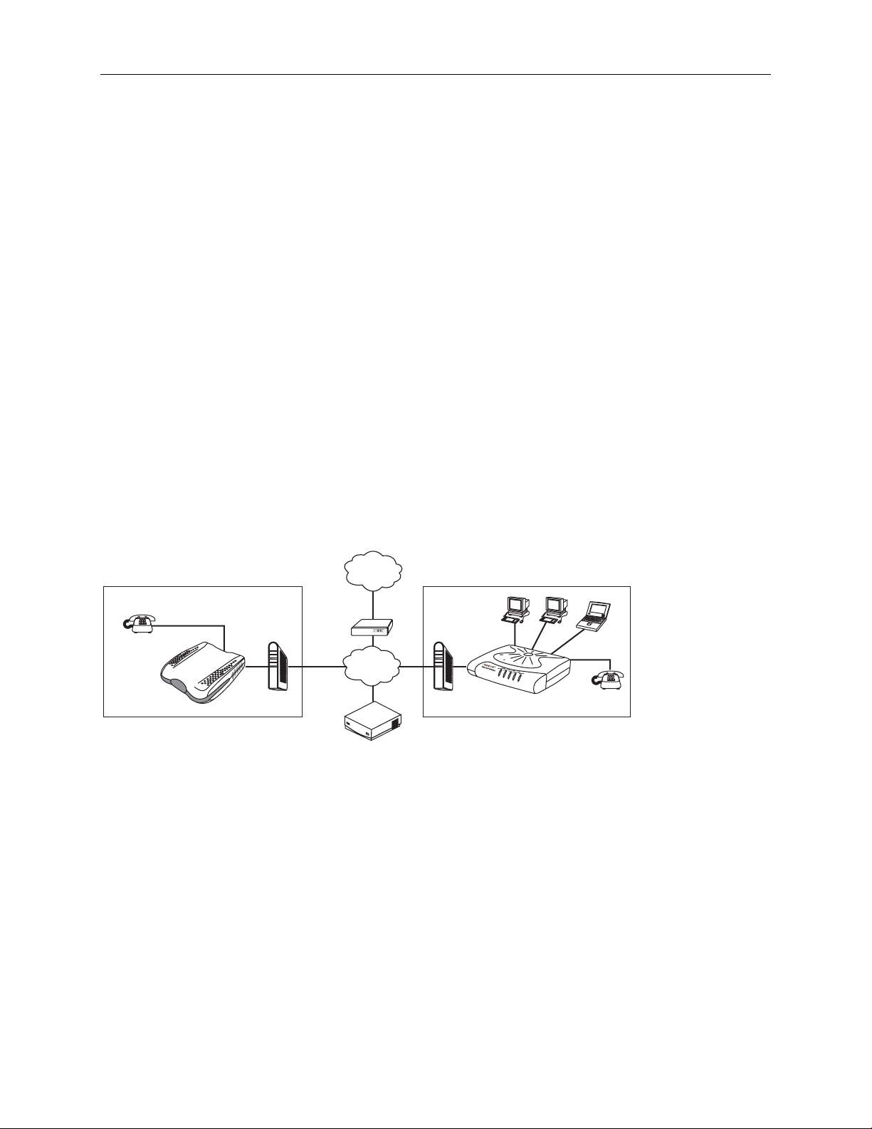
1.3 Applications
PSTN
Trunking
FXS
1810
Location 1 Location 2
DSL/Cable
Modem
Gateway
VoIP
Gatekeeper/Proxy Server
IP
Ethernet
1813
FXS
05-17635
7
Page 8
1810 VoIP Gateway User’s Guide
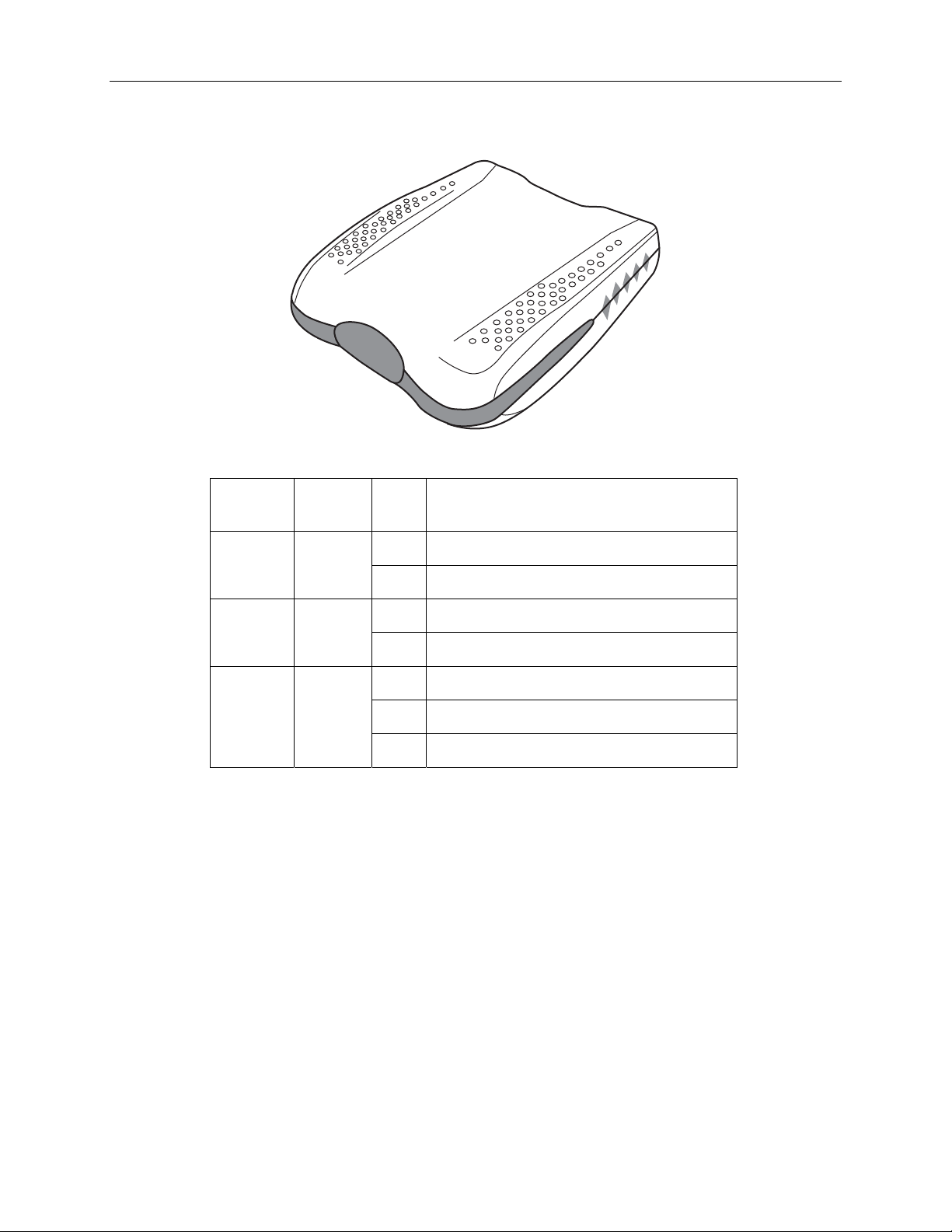
1.4 Front Panel LED Indicators
WA
N
PHONE
POWER
05-17624
LED
Indicator
Color Mode Function
On A power connection is established. POWER Green
Off No power connection is established.
On The WAN link is established. WAN Green
Off The WAN link is not established.
PHONE
Green
On Phone is off-hook.
Off Phone is on-hook.
Flash Hardware is initializing.
Note: If the device fails to power on, or it malfunctions, first verify that the power supply is correctly
connected, and then power on the device again.
8
Page 9

18 10 VoIP Gateway User’ s Guide
Chapter 2 Hardware Installation
The figure below illustrates the back panel of the gateway.
P
hone
P
Telephone
Cable
(RJ11)
Telephone
ower
Power Cable
3
1
W
AN
2
Internet
05-17623
DSL LAN Port
DSL Modem
1. Connect the power adapter to the POWER jack of the device, and then plug the power adapter into
the wall outlet.
2. Connect the WAN port to your DSL modem’s LAN port using a standard RJ45-to-RJ45 cable.
3. Connect the telephone set to PHONE port for VoIP service using a standard RJ11-to-RJ11 cable.
If the device fails to power on, or it malfunctions, first verify that the power supply is correctly connected,
and then power it on again.
2.1 Reset Button
In the middle of the rear panel is a reset button. This button is used to reload the factory default settings.
Use a small object like a ballpoint pen to press the button and hold it down for over three seconds. The
gateway will reset itself and all parameters will return to their factory default settings. You can verify this
process by monitoring the PHONE LED, which will turn off and then on again as the gateway restarts.
9
Page 10
1810 VoIP Gateway User’s Guide
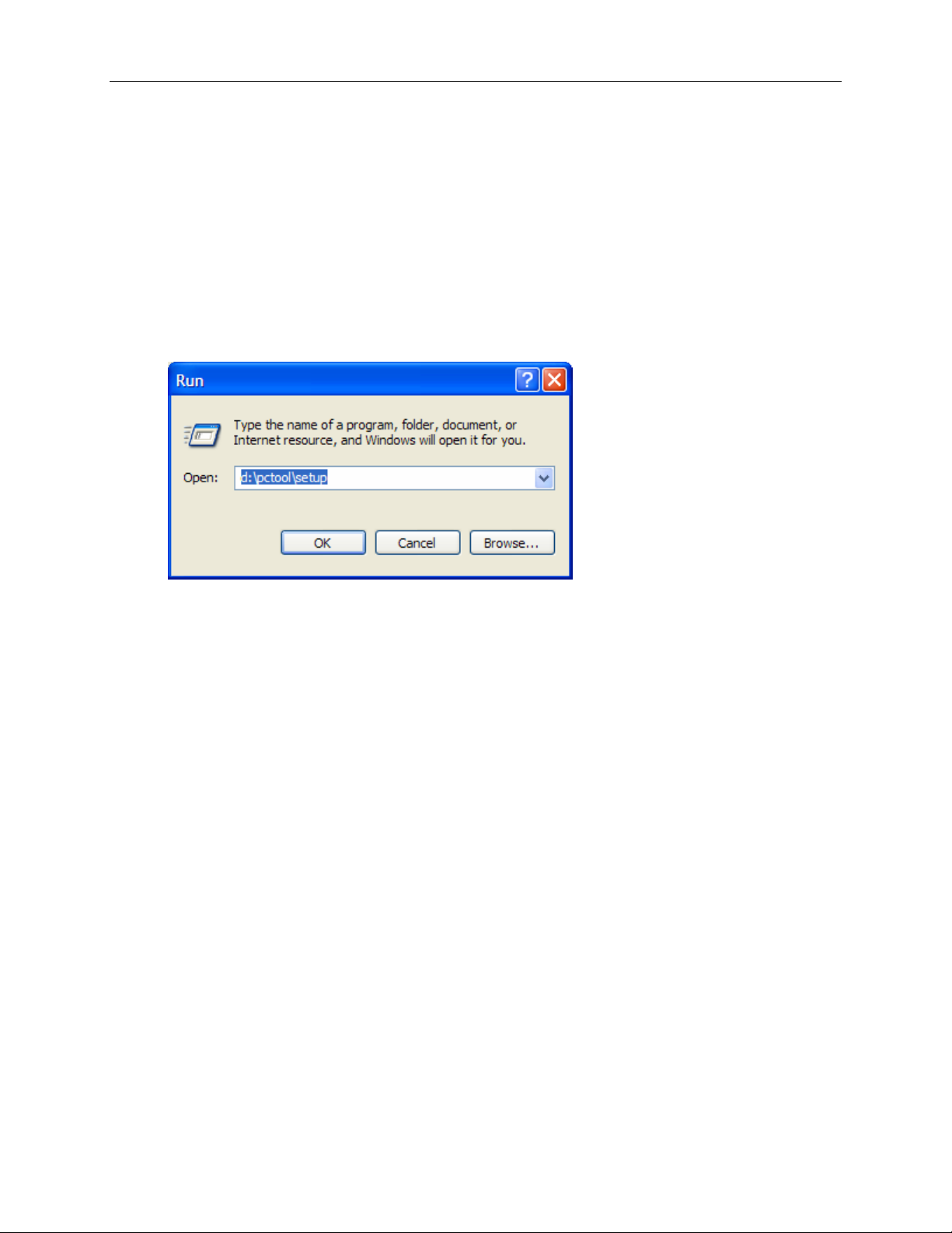
Chapter 3 Installing and Starting PCTool
You can configure and manage the gateway using the provided PCTool application.
To install and run PCTool:
1. Connect the WAN port of the gateway to the Network Interface Card (NIC) of your PC using the
supplied Ethernet cable.
2. Insert the provided CD in the CD drive of your PC.
3. From the Windows Start menu, select Run. Type:
d:\pctool\setup
where d: is the drive identifier for your CD drive. Click on OK.
4. The installer will install PCTool in the c:\Program Files\JetFusion 1810 directory and start it. In
the future you can initiate the program by browsing to that directory using Windows Explorer and
double-clicking on PCTool.exe. The gateway must be attached to your PC when you use PCTool.
5. When you are done using PCTool, reconnect the LAN port of your DSL modem to the WAN port
of the gateway as shown in Hardware Installation, above.
10
Page 11

18 10 VoIP Gateway User’ s Guide
Chapter 4 Status
Upon startup of PCTool the screen below is displayed.
11
Page 12

1810 VoIP Gateway User’s Guide
Chapter 5 Configuration
Click on the Connection Mode tab to configure the connection mode.
5.1 Connection Modes
There are three connection modes:
PPPoE
DHCP
Fixed IP
The Refresh button refreshes the screen, and the Close button closes the application.
12
Page 13

18 10 VoIP Gateway User’ s Guide
5.1.1 PPPoE
To configure PPPoE as the connection mode, select it on the left side of the screen. Then enter the User
name, Password and Confirm Password parameters.
User name: Enter the required user name.
Password: Enter your new password (letters are case sensitive) as provided by your Internet service
provider.
Confirm Password: Enter the password again for confirmation purposes.
Click on Apply to submit the settings. If the connection is successful, the following message is displayed:
Note: The same message should be displayed for the successful connection of DCHP or Fixed IP.
13
Page 14

1810 VoIP Gateway User’s Guide
5.1.2 DHCP
To configure DHCP as the connection mode, select it on the left side of the screen and click on Apply to
submit the settings.
14
Page 15

18 10 VoIP Gateway User’ s Guide
5.1.3 Fixed IP
To configure Fixed IP as the connection mode, select it on the left side of the screen. Then enter the IP
Address, Subnet Mask, Default Gateway and DNS (Domain Name Server) parameters.
IP Address: Enter your fixed IP address as given to you by your Internet service provider.
Subnet Mask: Enter a subnet mask to identify the subnet portion of your network address.
Default Gateway: Enter the address of the next-hop router.
DNS: Enter the IP address of your primary Domain Name Server (DNS 1), and if available, your
secondary DNS (DNS 2).
15
Page 16

1810 VoIP Gateway User’s Guide
Chapter 6 SIP
SIP, the Session Initiation Protocol, is a signaling protocol for Internet conferencing, telephony, presence,
events notification, and instant messaging. It is the Internet Engineering Task Force's (IETF's) standard
for multimedia conferencing over IP. It is designed to address the functions of signaling and session
management within a packet telephony network. Signaling allows call information to be carried across
network boundaries. Session management provides the ability to control the attributes of an end-to-end
call.
Session Initiation Protocol is a peer-to-peer protocol. There are four components in the SIP standard:
User Agent (UA)
Proxy Server
Registrar Server
Redirect Server
This document is concerned with SIP User Agent and the call establishment between User Agents.
To access SIP, click on the SIP tab. The following screen is displayed.
16
Page 17

18 10 VoIP Gateway User’ s Guide
6.1 Local
To configure the local settings, click on the Local tab. Then fill in or select the parameters and click on Apply.
Parameter Description
Max Digits(1-14) Enter the maximum number of digits you will dial.
Port No. Port number of user agent where it receives the SIP messages. The default
port number is 5060, which is a well-known port for SIP protocol.
Max Rings
Use Proxy
User Name
Display Name Displays name of the above user. It is for identification purpose only, and
Codec The preferred Codec of this user. The default is PCMU.
DTMF
Proxy/ Registrar
Info
Port No Port number of user-agent where it receives the SIP messages. The default
Specify a number from 1 to 50. This represents the number of times you
require the phone to ring for an incoming call.
Choose YES if a Proxy or Registrar server will be used. Also configure the
Proxy Info and Registrar. Choose No if a Proxy/Registrar server won’t be
used. With this setting, the proxy and registrar information will be ignored.
Name of the local SIP host.
can be used to hide the actual user name
Select the Dual Tone Multi-Frequency (DTMF) setting from the drop-down
list: In-Band or RFC 2833.
A proxy is an intermediary program that acts as both a server and a client
for the purpose of making requests on behalf of other clients. Requests are
serviced internally or transferred to other servers. A proxy interprets and if
necessary rewrites a request message before forwarding it.
Input IP address of the SIP proxy server, used for VOIP service.
port number is 5060, which is a well-known port for SIP protocol.
Domain Info
Auth User Name The authentication user name for the Registrar/proxy, which is assigned by
Auth Password The authentication password for the Registrar/proxy, which is assigned by
Expire The time period until user would like its registration to be valid with the
17
The Registrar saves information about where a party can be found.
Input the domain name of the SIP Registrar server.
the service provider.
the service provider.
Registrar/Proxy Server. The default value is 120 seconds.
Page 18

1810 VoIP Gateway User’s Guide
Parameter Description
Qvalue Enter a value between 0 and 1 for registering with the proxy (in case the
same username is registered from a different location). Decimals are
accepted, such as 0.3.
In general, a larger number has higher priority for the proxy to connect the
call. If the same Qvalue is used, the call connection is up to the call policy of
the proxy.
6.2 Call Forward
To configure the call forwarding parameters, input the items and click on Apply.
18
Page 19

18 10 VoIP Gateway User’ s Guide
Parameter Description
User Name Sip user name of the forwarding address where the calls will be
forwarded.
IP Addr or
Domain Name
The IP address or domain name of the SIP user name to which the
phone calls will be forwarded.
Port No Port number of the forwarding address where the calls will be
forwarded. The default port number is 5060.
Fwd Call
Choose YES if the calls will be forwarded. Choose NO if the
calls won’t be forwarded.
NumRings Input a number between 1-20. This represents the number of times the
phone will ring before the call is forwarded.
19
Page 20

1810 VoIP Gateway User’s Guide
6.3 STUN
To configure the STUN (Simple Traversal of UDP through NATs) server parameters, input the items and
click on Apply.
Parameter Description
STUN IP or
Domain Name
Port No Port number of the STUN server where the packets will be forwarded.
STUN type This column is read-only. The STUN mechanism will determine your
20
The IP address or domain name of the STUN server. This could be
provided by your service provider, or you could use a free STUN server
on Internet.
The default port number is 5060.
NAT type and display on the screen.
Page 21

18 10 VoIP Gateway User’ s Guide
Chapter 7 Telephone Book
This can be used to store numbers based on Destination IP or Host Name.
7.1 Adding an Entry
To place an entry in the telephone book, click on the Telephone Book tab. Then click on Add.
21
Page 22

1810 VoIP Gateway User’s Guide
The following screen is displayed.
You are required to enter the following:
Parameter Description
User Name Input the user name.
Dest. Phone Number Input the destination phone number, which can have
up to fifteen digits. No spaces are permitted between
the digits.
Dest. IP Address or Host Name Input destination Ip address or host name.
Display Name Input the display name that you want to be displayed
at the other end.
Click on OK. The entries are displayed as shown below.
22
Page 23

18 10 VoIP Gateway User’ s Guide
7.2 Deleting an Entry
To delete an entry, select the entry on the left side of the screen as shown below, then click on the Del
button.
23
Page 24

1810 VoIP Gateway User’s Guide
Chapter 8 Tools
To access this screen, click the Tool tab.
24
Page 25

18 10 VoIP Gateway User’ s Guide
8.1 Upgrade
To enter this screen, first click on Tool, then Upgrade.
25
Page 26

1810 VoIP Gateway User’s Guide
8.2 Diagnostic
To enter this screen, first click on Tool, then Diagnostic. To Ping a host, enter its IP Address or Host Name. Click on Submit.
26
Page 27

18 10 VoIP Gateway User’ s Guide
8.3 System
To enter this screen, first click on Tool, then System.
27
Page 28

1810 VoIP Gateway User’s Guide
8.3.1 Save Current Configuration
To save the current configuration click Save.
The following confirm prompt is displayed.
To save the changes to flash memory click Yes.
28
Page 29

18 10 VoIP Gateway User’ s Guide
8.3.2 Reset To Factory Configuration
To reset the gateway to its factory configuration (default settings), click on Default.
The following warning prompt is displayed.
If you are sure that you want to load the default settings, click on Yes. The application will then close and
subsequently reboot. The gateway takes about thirty seconds to start up.
29
Page 30

1810 VoIP Gateway User’s Guide
8.3.3 Reboot Device
To reboot the device, click on Reboot.
The following warning prompt is displayed.
If you are sure that you want to reboot the device, click on OK. The application will then close and
subsequently reboot. The gateway takes about thirty seconds to start up.
30
Page 31

18 10 VoIP Gateway User’ s Guide
Appendix A: GLOSSARY
Default: The value assigned to a configuration parameter when the gateway is first powered on.
DHCP: Dynamic Host Configuration Protocol. A TCP/IP protocol that lets a network connected to the
Internet automatically assign a temporary IP address to a host when the host connects to the
network.
Ethernet address: Another name for MAC address.
Ethernet: A standard protocol (IEEE 802.3) for a 10-Mbps baseband local area network (PAT) bus
that supports high-speed communication among systems. It operates at the Physical Layer of
the OSI Model.
gateway: A communications device that connects two different networks.
IP address:
Internet Protocol address. The address assigned to an Internet host.
ISP: Internet Service Provider. An organization that provides access to the Internet.
network address: The network portion of an IP address.
ping: An echo request sent to check the accessibility of a device.
PPPoE: Point-to-Point Protocol over Ethernet. A method for establishing sessions and encapsulating
PPP packets over an Ethernet, specified by RFC 2516.
protocol: A set of rules that govern the transmission of data between interconnected devices to
maintain or improve communication.
PSTN: Public Switched Telephone Network. The standard telephone network.
remote host: A host connected to, and distinguished from, the local host.
RJ11: A 6-position jack used with dial networks and telephone sets.
RJ45: An 8-position jack used with programmable dial networks.
server: Hardware or software that offers a specific service, such as database management, to a client.
subnet address: The subnet portion of an IP address.
subnet mask: A number that identifies the subnet portion of a network address, so that IP addresses
can be shared on a local area network.
subnet: An addressable independent network segment.
xDSL: A generic term for all varieties of DSL.
31
 Loading...