

Paradyne 3811, 3810, 175-0018-0031 Installation Instructions Manual
FERRITE CHOKE, PART NUMBER 175-0018-0031
Installation Instructions
Document Number 3810-A2-GZ42-20
December 1999
OVERVIEW
T wo ferrite chokes and cable ties are shipped with every Model 3811 modem. To ensure compliance with FCC
Part 15 Regulations, a ferrite coke must be installed on both the EIA-232-D interface cable and the RS-366-A
interface cable.
INSTALLATION
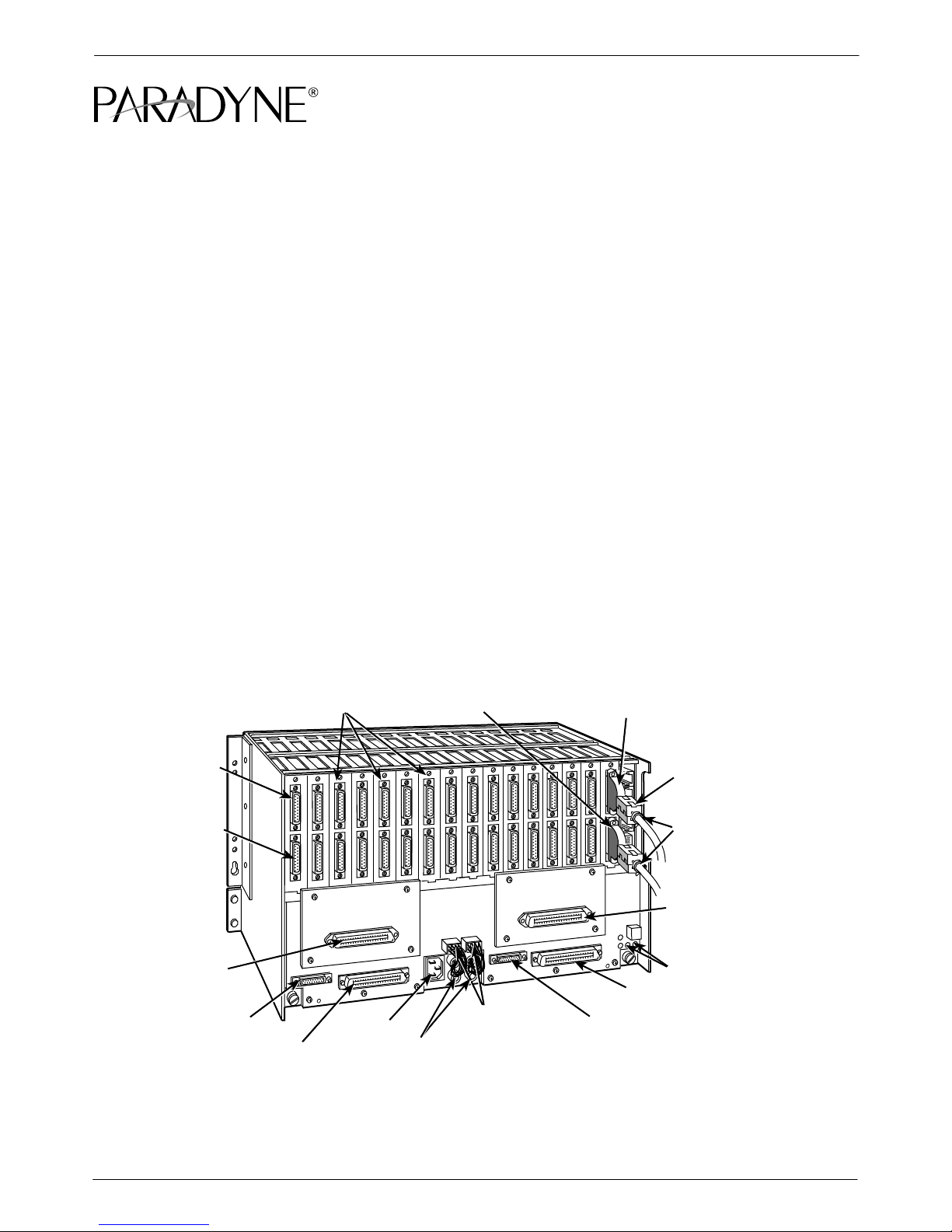
Use Figure 1 and the following procedures to install the ferrite chokes and cable ties on to the DTE interface
cables.
1. Open the ferrite choke and place it around one of the DTE cables as close as possible to the DTE
connector attached to the rear connector plate.
2. Close the two halves around the cable and snap the ferrite choke shut, pressing down on the plastic latch
to secure it.
3. Install a cable tie behind the ferrite choke to prevent it from sliding along the cable.
4. If a second DTE cable is attached to the rear connector plate, repeat Steps 1–3.
RS-366-A
DTE
CONNECTOR
POWER
CONNECTORS
EIA-232-D
CONNECTOR
FUTURE USE
EIA-232/V.24
INTERFACE
RS-366-A/V.25
INTERFACE
DIAL
NETWORK
INTERFACE
MODULE
(SLOTS 9 – 16)
FUTURE USE
CONNECTOR
PLATES
LEASED
INTERFACE
(SLOTS 9 – 16)
REAR
AC
POWER
FUSES
DTE
FERRITE
CHOKE
CABLE TIES
DIAL NETWORK
INTERFACE MODULE
(SLOTS 1 – 8)
ALARM E1 & E2
LEASED INTERFACE
(SLOTS 1 – 8)
00-13159-01
Figure 1. Ferrite Choke Installation
13810-A2–GZ42-20 December 1999
 Loading...