

Page 1
‘
12V
DC
Battery
+
-
Relay Module
N.O. N.C. C +
_
+
-
24V
DC
Power supply
(Max 28V)
~ ~
16/24V
AC
Power supply
or
23 24 25 26 27 2819 20 21 22 29 30 31 32
3456
789 101112 13 14 15 16 17 1812
C
C
C
C
C
C
C
C
C
C
C
INPUT
INPUT INPUT
INPUT
INPUT
INPUT
C
16 / 24 Vac
AUX
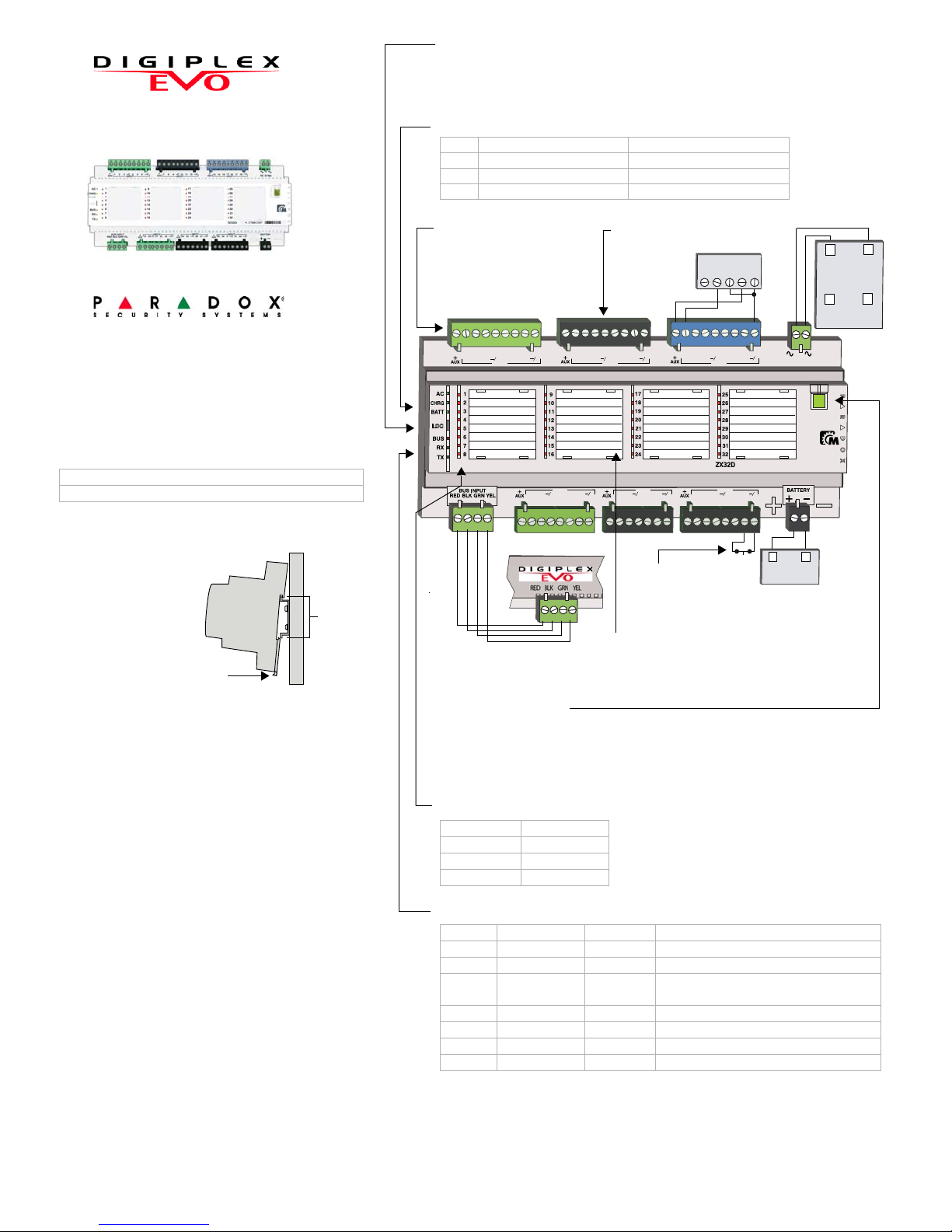
Zone Labels
Space is provided to label each zone.
Zone Connections
Connect detection devices
as described in “Hardwired
Zone Inputs” in the Imperial
Reference and Installation
manual.
Use
supplied
battery
cable.
Detachable
Terminals
Pry with
screwdriver if
necessary.
External Module
Tamper Switch
(N.C.)
The ZX32D 32-zone Expansion Module connects to the
Imperial control panel’s Combus and acts as an interface
between the control panel and any hardwired detection
devices. The ZX32D also includes an external 16/24Vac
or 24Vdc power supply input that can be used to power
connected devices.
Compatibility
Installation
The ZX32D is a
standard 35mm DIN
rail module. Using the
supplied DIN rail, the
ZX32D can be
mounted in any
location. Alternatively,
it can be mounted in
a standard DIN rail
enclosure. To attach
the module, align the
top of the DIN rail as
shown in Figure 1 and apply pressure to the module until
it clicks into place. To remove the ZX32D from a DIN rail,
pull the release clip and remove the module.
To facilitate installation and servicing, the ZX32D
terminals can be detached from the module. Wires can
be labeled using the supplied tie wraps.
NOTE: The ZX32D does not support ATZ zone doubling.
Upgrading the Firmware
The ZX32D firmware can be upgraded through WinLoad
using the CV4USB RS-485/RS-232 Converter. Refer to
the firmware upgrade instructions found at: paradox.com
- Software - WinLoad - Firmware Upgrade Instructions
EVO48, EVO192
DGP-848, DGP-NE96, EVO96
Figure 1: DIN Rail Mounting
Release
clip
35mm
DIN rail
LOC Button
The ZX32D LOC button is used to enter Test Mode (see page 2).
A Module Locate can be performed using section [4002] (EVO) or [952] (DGP-48
/ DGP-848). To end a module locate, press and hold LOC for 2 seconds.
Manual Controls
The ZX32D supplies 1A to power security system modules. By pressing the AUX
button, the 13.8Vdc auxiliary power supply can be manually activated (LED green)
or deactivated (LED off), allowing modules to be powered down without shutting
down the control panel. If input power is lost, the AUX buttons will stop functioning.
When power is restored, the button will resume its previous state.
ZX32D-EI01
PARADOX.COM
Printed in Canada - 11/2008
Instructions
ZX32D
32-Zone Expansion Module V1.0
Communication LED Feedback
BUS RX (from panel) TX (to panel ) Condition
green green flash green flash OK (panel communication in progress)
red on off off Short on GRN or YEL
red on off green Communication failure / T oo many
modules on bus
red on green green Bus lines reversed (GRN / YEL)
red flash off off Bus power too low
red flash green flash green flash Locate mode
blue flash off off Firmware upgrade in progress
Power LED Feedback
LED Colour Condition
AC green on AC or DC power is supplied
CHRG green on Battery is low / charging
BATT green on (less than 4 sec.) Battery test
Zone LED Feedback
LED Status
off zone closed
red zone open
red flash zone tamper
Page 2
Test Mode
*This feature will be available on future versions.
Mode Feature LED Feedback Instructions
Mode 1 Input assignment RX flashes x 1 Entering Mode 1 illuminates all zones that have already been assigned in the control panel.*
Mode 2 EOL disabled
Tamper disabled
RX flashes x 2 Entering Mode 2 sets the ZX32D for: No EOL / No tamper. To verify correct EOL / tamper wiring,
open and close the zone and verify that the zone’s LED reacts accordingly.
Mode 3 EOL enabled
Tamper disabled
RX flashes x 3 Entering Mode 3 sets the ZX32D for: With EOL / No tamper. To verify correct EOL / tamper wiring,
open and close the zone and verify that the zone’s LED reacts accordingly.
Mode 4 EOL enabled
Tamper enabled
RX flashes x 4 Entering Mode 4 sets the ZX32D for: With EOL / With tamper. To verify correct EOL / tamper
wiring, open and close the zone and verify that the zone’s LED reacts accordingly.
Mode 5 Zone test RX flashes x 5 Entering Mode 5 illuminates all connected zones. When a zone is triggered, the corresponding zone
LED will turn off, indicating correct wiring.
Base Time Selection - Even-numbered sections Time Value - Odd-numbered sections
Even-numbered sections represent the base time selection for inputs
terminals Z1 to Z32. Using the [T] and [S] keys, select a base time* value
from 000 to 002. To save and proceed to the next section, Press [
ENTER].
Odd-numbered sections represent time value for inputs Z1 to Z32. Enter a
3-digit decimal time value (000 to 255). Multiply by the selected base time.
Technical Specifications
Input voltage: 16 to 24 Vac or 24 Vdc
AUX power 12Vdc, 1A maximu m
Current consumption: 154mA maximum
Number of zones: 32 standard zone inputs
Operating Temperature -20ºC to 50ºC (-4ºF to 122ºF)
Warranty
For complete warranty information on this product please refer to the Limited Warranty Statement found on the
website www.paradox.com/terms. Your use of the Paradox product signifies your acceptance of all warranty
terms and conditions.
Digiplex EVO is trademark or registered trademark of Paradox Security Systems Ltd. or its affiliates in Canada,
the United States and/or other countries. For the latest information on products approvals, such as UL and CE,
please visit www.paradox.com.
© 2008 Paradox Security Systems Ltd. All rights reserved. Specifications may change without prior notice. One
or more of the following US patents may apply: 7046142, 6215399, 6111256, 6104319, 5920259, 5886632,
5721542, 5287111, 5119069, 5077549 and RE39406 and other pending patents may apply. Canadian and
international patents may also apply .
To facilitate installation and verify correct wiring, the ZX32D features five Test Modes. In order to use this feature, the ZX32D module must be powered
(Test Mode 1 requires a full bus connection). To enter Test Mode, press the LOC button. The ZX32D enters Test Mode 1. Press the LOC button again to
enter Test Mode 2, and so on. On the sixth press, the ZX32D will exit Test Mode.
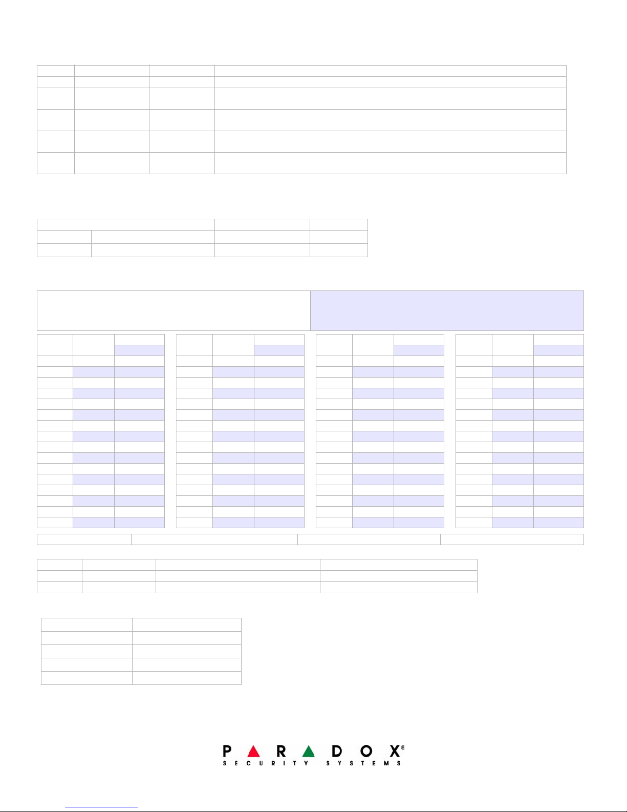
EVO Programming
General Options
Section [001] OFF ON
Option [1] Tamper Recognition (zone 32)
Option [2] Battery Charge Current
Zone Input Speed
To calculate the zone input speed, multiply the Base Time Selection by the Time Value. (default = all inputs 600ms)
NDisabled (default) N Enabled
N350mA (default) N 850 mA
Section Base Time*
Zone
Zone 1 [002] ___/___/___ Zone 9 [018] ___/___/___ Zone 17 [034] ___/___/___ Zone 25 [050] ___/___/___
[003] ___/___/___ [019] ___/___/___ [035] ___/___/___ [051] ___/___/___
Zone 2 [004] ___/___/___ Zone 10 [020] ___/___/___ Zone 18 [036] ___/___/___ Zone 26 [052] ___/___/___
[005] ___/___/___ [021] ___/___/___ [037] ___/___/___ [053] ___/___/___
Zone 3 [006] ___/___/___ Zone 11 [022] ___/___/___ Zone 19 [038] ___/___/___ Zone 27 [054] ___/___/___
[007] ___/___/___ [023] ___/___/___ [039] ___/___/___ [055] ___/___/___
Zone 4 [008] ___/___/___ Zone 12 [024] ___/___/___ Zone 20 [040] ___/___/___ Zone 28 [056] ___/___/___
[009] ___/___/___ [025] ___/___/___ [041] ___/___/___ [057] ___/___/___
Zone 5 [010] ___/___/___ Zone 13 [026] ___/___/___ Zone 21 [042] ___/___/___ Zone 29 [058] ___/___/___
[011] ___/___/___ [027] ___/___/___ [043] ___/___/___ [059] ___/___/___
Zone 6 [012] ___/___/___ Zone 14 [028] ___/___/___ Zone 22 [044] ___/___/___ Zone 30 [060] ___/___/___
[013] ___/___/___ [029] ___/___/___ [045] ___/___/___ [061] ___/___/___
Zone 7 [014] ___/___/___ Zone 15 [030] ___/___/___ Zone 23 [046] ___/___/___ Zone 31 [062] ___/___/___
[015] ___/___/___ [031] ___/___/___ [047] ___/___/___ [063] ___/___/___
Zone 8 [016] ___/___/___ Zone 16 [032] ___/___/___ Zone 24 [048] ___/___/___ Zone 32 [064] ___/___/___
[017] ___/___/___ [033] ___/___/___ [049] ___/___/___ [065] ___/___/___
*Base Time Selection 000 = Input Speed is X by 30 milliseconds. 001 = Input Speed is X by 1 second. 002 = Input Speed is X by 1 minute.
AC Fail Report Delay Timer
Section Data Description
[066] ___/___/___ (000 to 255) minutes (default = 30) AC Fail Report Delay
[067] ___/___/___ (000 to 255) minutes (default = 5) AC Fail Report Delay Restore
Time Value Time Value Time Value Time Value
Section Base Time*
Zone
Section Base Time*
Zone
Section Base Time*
Zone
PARADOX.COM
Printed in Canada - 11/2008 ZX32D-EI01
 Loading...