

Page 1
UC300 Universal Converter
Reference and Installation Manual
UC300-EI02
Printed in Canada | 03/2015
Page 2

Warranty
For complete warranty information on this product, please refer to the Limited Warranty Statement found
www.paradox.com/terms. The terms and conditions are subject to change without notice, from time to time, at
Paradox’s sole discretion. We invite you to visit our website on a regular basis for the latest Limited Warranty
Statement. Your use of the Paradox product signifies your acceptance of all warranty terms and conditions.
Please ensure tat your use of the Paradox product is in compliance with local, national, and internal laws.
©2014 Paradox Security Systems Ltd. All rights reserved. Specifications may change without prior notice. US,
Canadian and international patents may apply. Paradox and BabyWare are trademarks or registered trademarks
of Paradox Security Systems (Bahamas) Ltd. or its affiliates in Canada, the United States and/or other countries.
This product is manufactured in Canada.
Paradox
780 Industrial Boulevard
St-Eustache, Quebec
Canada, J7R 5V3
Tel: (450) 491-7444
Fax: (450) 491-2313
Page 3

Contents
Chapter 1 Introduction . . . . . . . . . . . . . . . . . . . . . . . . . . . . . . . . . . . . . . . . . . . . . 7
1.1 Compatibility . . . . . . . . . . . . . . . . . . . . . . . . . . . . . . . . . . . . . . . . . . . . . . . . . . . . . . . . . . . . .7
Chapter 2 Overview . . . . . . . . . . . . . . . . . . . . . . . . . . . . . . . . . . . . . . . . . . . . . . . . 8
2.1 Parallel and Backup . . . . . . . . . . . . . . . . . . . . . . . . . . . . . . . . . . . . . . . . . . . . . . . . . . . . . . .9
Chapter 3 Hardware . . . . . . . . . . . . . . . . . . . . . . . . . . . . . . . . . . . . . . . . . . . . . . . 10
3.1 UC300 Inputs and Outputs . . . . . . . . . . . . . . . . . . . . . . . . . . . . . . . . . . . . . . . . . . . . . . 10
3.2 LED Assignment . . . . . . . . . . . . . . . . . . . . . . . . . . . . . . . . . . . . . . . . . . . . . . . . . . . . . . . . 10
3.3 Requirements . . . . . . . . . . . . . . . . . . . . . . . . . . . . . . . . . . . . . . . . . . . . . . . . . . . . . . . . . . . 11
3.4 Reset . . . . . . . . . . . . . . . . . . . . . . . . . . . . . . . . . . . . . . . . . . . . . . . . . . . . . . . . . . . . . . . . . . . 14
3.5 Restart . . . . . . . . . . . . . . . . . . . . . . . . . . . . . . . . . . . . . . . . . . . . . . . . . . . . . . . . . . . . . . . . . . 14
Chapter 4 Configure with BabyWare . . . . . . . . . . . . . . . . . . . . . . . . . . . . . . . 15
4.1 Configure Account . . . . . . . . . . . . . . . . . . . . . . . . . . . . . . . . . . . . . . . . . . . . . . . . . . . . . . 15
4.2 Configure Properties . . . . . . . . . . . . . . . . . . . . . . . . . . . . . . . . . . . . . . . . . . . . . . . . . . . . 17
4.3 Users . . . . . . . . . . . . . . . . . . . . . . . . . . . . . . . . . . . . . . . . . . . . . . . . . . . . . . . . . . . . . . . . . . . 18
4.4 Reporting . . . . . . . . . . . . . . . . . . . . . . . . . . . . . . . . . . . . . . . . . . . . . . . . . . . . . . . . . . . . . . . 19
4.5 GPRS Settings . . . . . . . . . . . . . . . . . . . . . . . . . . . . . . . . . . . . . . . . . . . . . . . . . . . . . . . . . . . 21
4.6 SMS Settings . . . . . . . . . . . . . . . . . . . . . . . . . . . . . . . . . . . . . . . . . . . . . . . . . . . . . . . . . . . . 22
4.7 Configuring Receiver Settings . . . . . . . . . . . . . . . . . . . . . . . . . . . . . . . . . . . . . . . . . . . 23
4.8 Trouble Reporting . . . . . . . . . . . . . . . . . . . . . . . . . . . . . . . . . . . . . . . . . . . . . . . . . . . . . . . 24
4.9 Reporting Sequence (Parallel or Serial) . . . . . . . . . . . . . . . . . . . . . . . . . . . . . . . . . . . 24
4.10 PC Communication . . . . . . . . . . . . . . . . . . . . . . . . . . . . . . . . . . . . . . . . . . . . . . . . . . . . . . 25
4.11 Other Settings . . . . . . . . . . . . . . . . . . . . . . . . . . . . . . . . . . . . . . . . . . . . . . . . . . . . . . . . . . 25
4.12 Firmware updating . . . . . . . . . . . . . . . . . . . . . . . . . . . . . . . . . . . . . . . . . . . . . . . . . . . . . . 26
4.13 SMS / Text Messages . . . . . . . . . . . . . . . . . . . . . . . . . . . . . . . . . . . . . . . . . . . . . . . . . . . . 26
Chapter 5 Entering Email Addresses to a Reporting List . . . . . . . . . . . . . 27
Appendix A Specifications . . . . . . . . . . . . . . . . . . . . . . . . . . . . . . . . . . . . . . . . . . . 28
Appendix B Certifications . . . . . . . . . . . . . . . . . . . . . . . . . . . . . . . . . . . . . . . . . . . 28
Appendix C Configuration of the PCS250/PCS250G. . . . . . . . . . . . . . . . . . . . 28
Appendix D Error Reporting . . . . . . . . . . . . . . . . . . . . . . . . . . . . . . . . . . . . . . . . . 29
Page 4

Chapter 1: Introduction
The Paradox Universal Converter, the UC300, is an innovative device that allows the CMS to receive events and
alarms from any security control panel via a Paradox IP receiver. The UC300 provides the link between CID
control panel security systems and Paradox communication devices, for example the IP150 and the
PCS250/PCS250G.
UC300 converts Contact ID (CID) events generated by a security panel connected to a landline interface into
Paradox proprietary protocol. Events are then forwarded to the monitoring station via IP150 and/or PCS250/
PCS250G.
The UC300 enables end-users to self-monitor their secured location by allowing receipt of instant, SSLencrypted emails (via IP150) and SMS (via PCS250/PCS20G) alerts from any location supplied by a wireless
provider once the system detects activity.
1.1 Compatibility
The UC300 is compatible with control panels that support a landline interface with CID reporting protocol.
The UC300 interfaces with the following Paradox products.
•IPR512
•IPRS7
• PCS250/PCS250G version 2.12 or higher
• IP150 version 1.32 or higher / Combo
• BabyWare version 2.9.7 or higher– for product configuration
• InField version 3.8 or higher (for device upgrades)
UC300 Universal Converter 4
Page 5

Chapter 2: Overview
The UC300, when combined with an IP150, a PCS250/PCS250G or both, forms a universal IP reporting solution
allowing the connection of CID control panels to Paradox IP receivers. It is a device that converts signals coming
from any panel using a landline interface with CID to Paradox proprietary protocol. This enables the end user to
take advantage of Paradox communication products to get and give reports from their current system to
Command Centers, Central Monitoring Systems, individuals, and emergency services.
This is a universal IP reporting solution that will complement your system communications with serial or
parallel notifications. This system is fully redundant with back-up connections and protocols so that your
system will continue to send reports under all adverse conditions.
Combined with IP150 and PCS250/PCS250G, the new UC300 will send reports through 3 separate media:
• Landline (done by the panel)
• IP with the IP150 module (supports email)
• GPRS with the PCS250/PCS250G module attached (supports personal SMS messages sent to up to eight
phone numbers)
Main features:
• Connected to the ring and tip output of any panel, the UC300 may be set to function as parallel or sequential
(serial) backup
• Reports in conjunction with landline or as a backup
• Receive, translate and forward the PSTN reporting using Paradox protocol (IPDOX)
• Supports up to 2 IP/GPRS receivers (IPR512/IPRS7/SDK) using Paradox proprietary protocol with primary and
secondary addresses for each receiver
• Emulates FXS telephone line which will allow panel reporting when there is no external telephone line
available
• Module configuration and status via Paradox BabyWare
• Reports via email to a maximum of 16 email accounts (when using IP150
• Reports via SMS to a maximum of 8 SMS phone numbers (when using PCS250/PCS250G)
• Firmware upgrades via IP, serial connection or GPRS
• Supports multiple languages for both the Web Interface of the IP150 and SMS
• Generates contact ID on phone line interface in order to emulate landline receiver
• Monitors the landline (can be configured)
• Switches automatically to the IP or GPRS reporting after a number of failed attempts on the landline
• Switches automatically to IP or GPRS reporting if no landline is detected by the built-in telephone line
monitoring (TLM) circuit. The UC300 also reports telephone line failure over IP/GPRS
• If needed (only if IP150 is installed) the module can be registered to PMH with polling option on/off
Programing the UC300 converter and/or reading the logs will be made via the BabyWare application using a
serial adapter (307USB connector), LAN (IP150) or GPRS (PCS250/PCS250G). In case of using PCS250/PCS250G
without the IP150, the first programing of the PCS250/PCS250G (APN, password, etc.) will be made by SMS
command or serial adapter (307USB).
Notes: 1. The UC300 with the IP150 and /or the PCS250/PCS250G should be configured through
BabyWare (except for email configuration by the end user).
2. For Compliance with EN 50136, FW upgrade should be performed by the manufacturer only.
5 UC300 Universal Converter
Page 6

2.1 Parallel and Backup
The UC300 supports two reporting sequences. Configuring the Reporting Sequence is done through
BabyWare =>Reporting => Reporting Sequence. Each reporting sequence should be linked to a specific phone
number.
The two methods of reporting include:
• Serial Reporting (Backup) – defines the primary method for reporting and the number of failed attempts.
Once the number of failed attempts is reached the UC300 will switch to the backup reporting channels if
defined. Each reporting sequence supports up to 3 channels (primary + 2 backups).
• Parallel Reporting - all report codes are transmitted simultaneously over all available media channels
(GPRS and IP). In parallel reporting, the first media to receive a confirmation will stop reporting on other
channels.
UC300 Universal Converter 6
Page 7
Chapter 3: Hardware
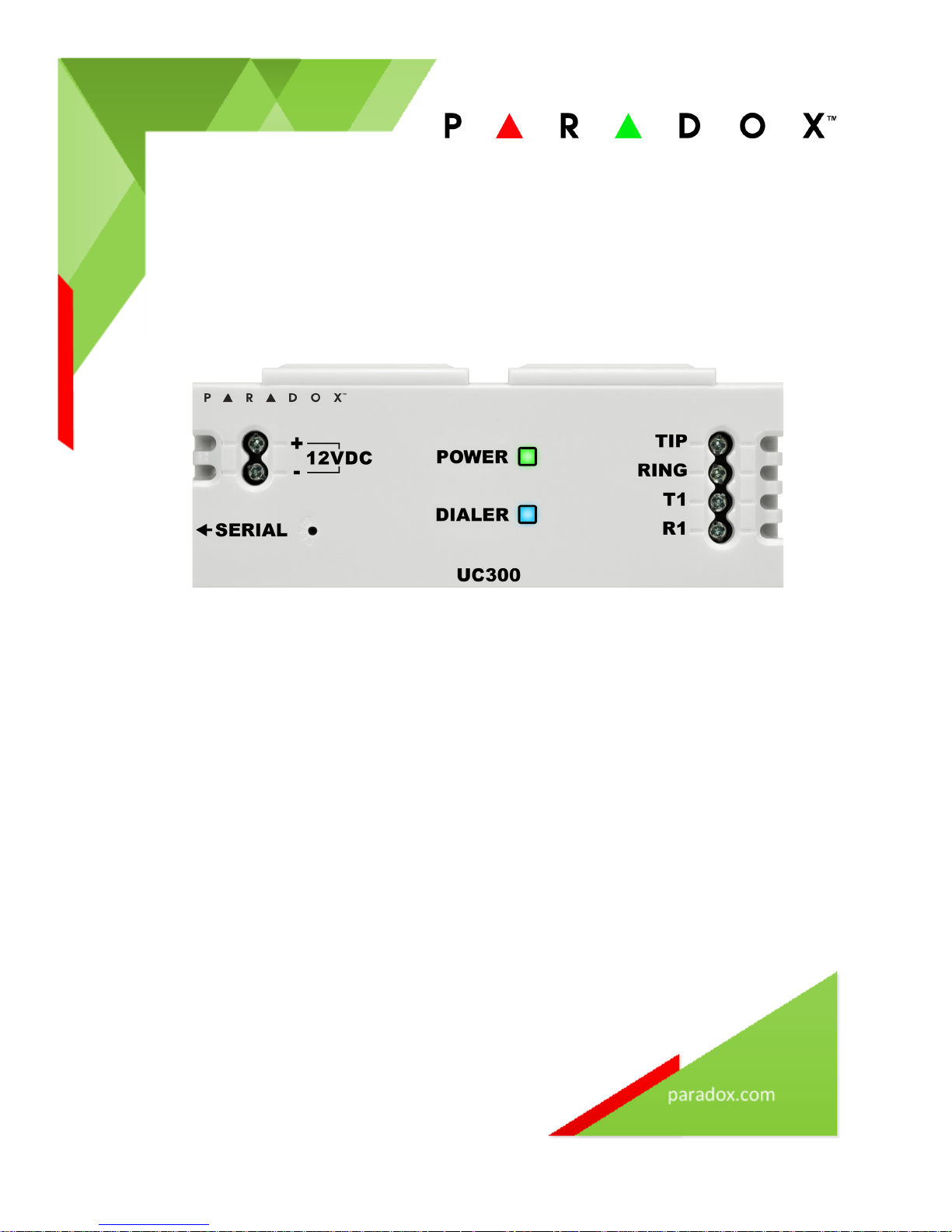
3.1 UC300 Inputs and Outputs
Figure 1 – UC300 LEDs
• Tip/ring – connect to the end user’s landline (not mandatory)
• T1/R1 – connect to the end user’s control panel telephone line
• Serial mini type connector – for FW upgrade, IP150 and PCS250/PCS250G connection
• DC in – supervised power input
• Two LEDs (green and blue see LED indication section)
• Reset switch
Warning : Connecting the Power Input to an AC/DC power source must be performed only with a safety
approved Limited Power Source (LPS) AC/DC adaptor.
Note: There is no need for a ground connection to the UC300 since the control panel has a ground
connection.
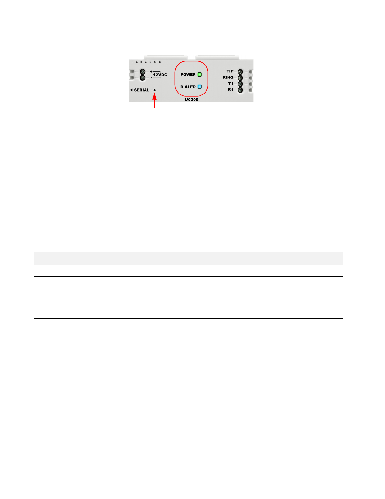
3.2 LED Assignment
3.2.1 Power – Green
Description Special Feature (Green) Behavior
< 9v Off
9v – 12v Slow (1s on, 1s off) flashing green
12v – 15v Recommended Operating Voltage Steady green
15v – 18v Fast (0.5s on, 0.5s off) flashing
green
> 18v Off
Note: The Green LED may take up to 15 seconds before it is activated in order to allow the “DC IN” time to
stabilize before it is analyzed.
7 UC300 Universal Converter
Page 8
3.2.2 Dialer Indication – Blue
Description Special Feature (Blue) Behavior
In report listening Steady blue
When data is recognized Flashing blue
3.2.3 Reset and Firmware Upgrade
Description Special Feature (Blue and Green) Behavior
Reset – after holding down the reset button for 5 seconds Blue and green flash fast
Reset – after confirmation Blue and Green off until reboot
complete
Firmware upgrade or no firmware present Blue Blinking fast
3.3 Requirements
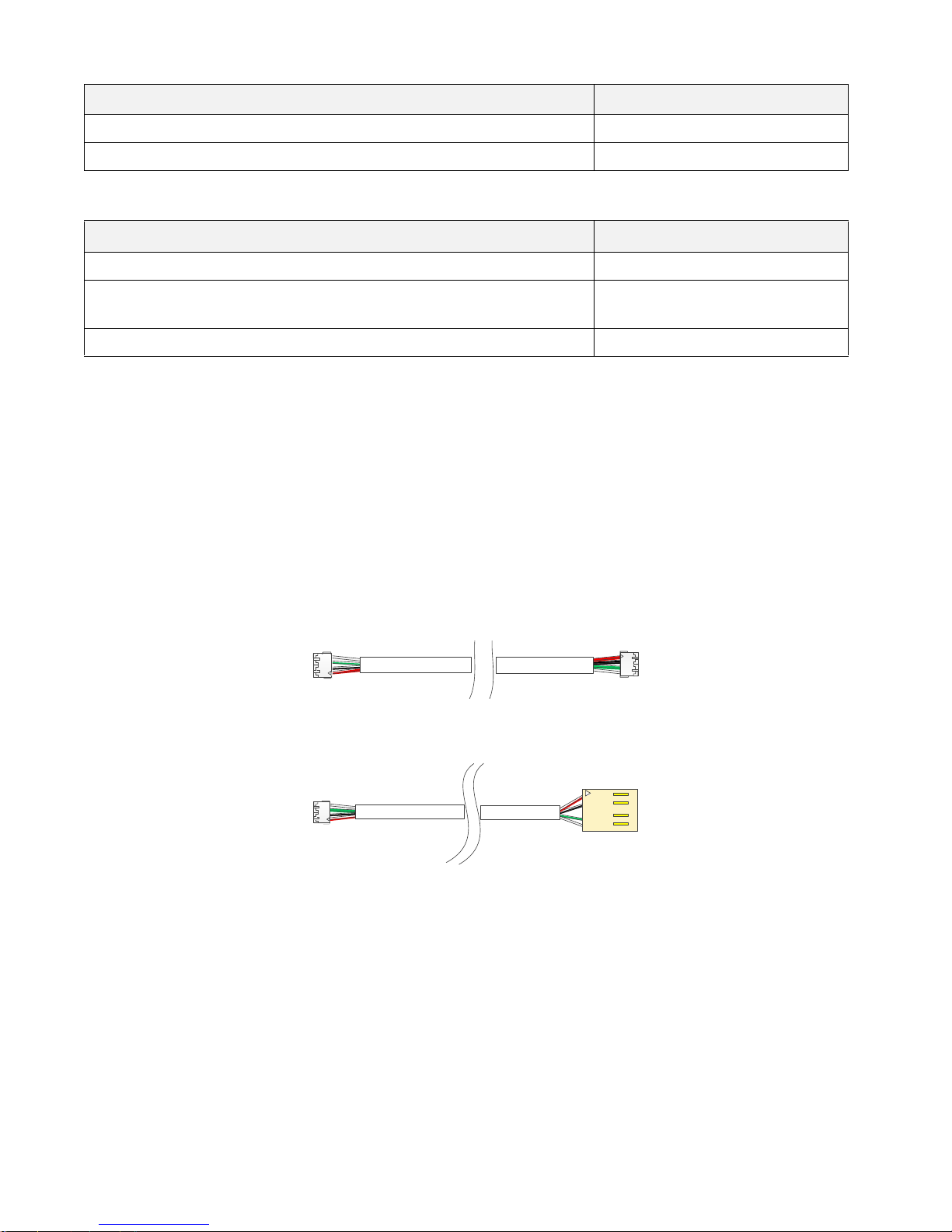
3.3.1 Cables
Depending on the setup you are using you will require some or all of the following cables.
Note: Extra cables may be ordered separately.
The following cables supplied in the box.
• 1 – UC300 to IP150 4 wire with two 0.8mm socket ends
1 – UC300/IP150 to PCS250/PCS250G 4 wire with one 0.8mm socket end and one 2.54mm socket end
•
Figure 2 – Connector Cable IP150 to UC300
Figure 3 – Connector Cable IP150/UC300 to PCS250/PCS250G
UC300 Universal Converter 8
Page 9
3.3.2 Hardware Installation 3 options.
Remove the serial cable from
the UC300 and connect this
cable from the 307USB to the
serial connection of the
UC300
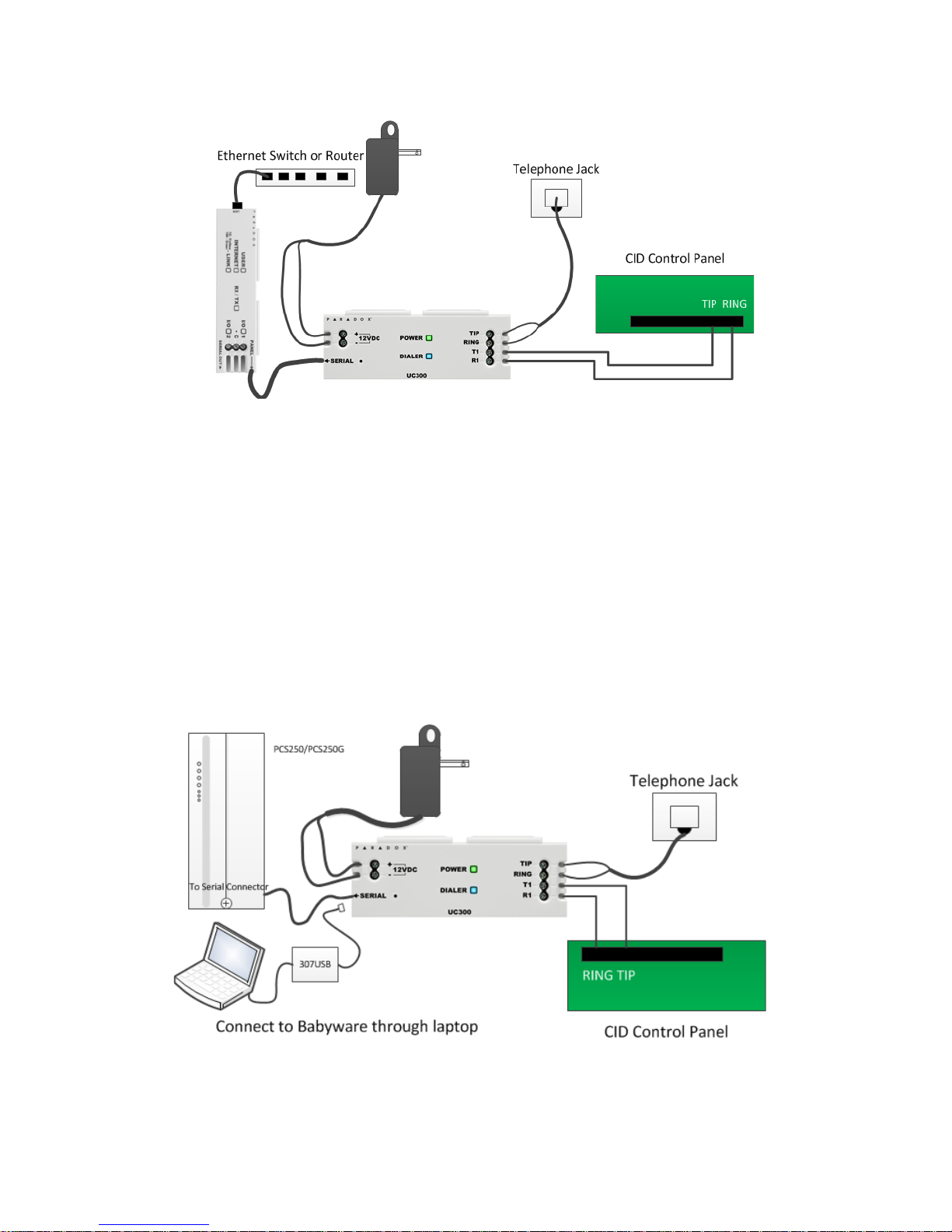
Option #1: IP150 Communication Device Only
Figure 4 – Connecting the UC300 with an IP150
1. Clip the UC300 to the system panel box.
2. Clip the IP150 to the system panel box near the UC300.
3. Plug in the UC300 to the IP150 using the IP150 panel port and the UC300 serial port. See Figure 2 for the
proper cable.
4. Connect the Tip and Ring from the UC300 to an outgoing telephone jack.
5. Connect the customer’s control panel Tip and Ring to the UC300 T1 and R1 terminals.
6. Connect the 12Vdc power supply to a supervised power supply or the auxiliary port of the control panel if it
provides 12v supply.
7. Connect an Ethernet cable from the IP150 to the LAN.
Warning : Connecting the Power Input to an AC/DC power source must be performed only with a safety
approved Limited Power Source (LPS) AC/DC adapter.
Option #2: PCS250/PCS250G Communication Device Only
Note: If you are programming the UC300 using the 307USB disconnect the PCS250/PCS250G, from the UC300
and connect the 307USB to the serial port. You may need to replace the serial cable with the cable in
Figure 3 within the 307USB.
9 UC300 Universal Converter
Figure 5 – Connecting the UC300 with a PCS250/PCS250G
Page 10

1. Clip the UC300 to the system panel box.
2. Plug in the PCS250/PCS250G cable between the UC300 serial port and the PCS250/PCS250G serial port. See
Figure 3 for the proper cable.
3. Connect the Tip and Ring from the UC300 to an outgoing telephone jack.
4. Connect the customer’s control panel Tip and Ring to the UC300 T1 and R1 terminals.
5. Connect the 12Vdc power supply to a supervised power supply.
6. Disconnect the cable from the UC300 Serial port and connect the IP150/UC300 to PCS250/PCS250G cable
from the 307USB to connect to your laptop. This will allow you to configure the setup using BabyWare. See
Figure 5
7. In BabyWare =>Accounts use Connection Option Serial.
Option #3: Both IP150 and PCS250/PCS250G Communication Devices
1. Clip the UC300 to the system panel box.
2. Clip the IP150 to the system panel box near the UC300.
3. Plug in the UC300 to the IP150 using the IP150 panel port and the UC300 serial port. See Figure 2 for the
proper cable.
4. Plug in the IP150 to the PCS250/PCS250G using the IP150 PCS250/PCS250G port and the PCS250/PCS250G
serial port. See Figure 3 for the proper cable.
5. Connect the Tip and Ring from the UC300 to an outgoing telephone jack.
6. Connect the customer’s control panel Tip and Ring to the UC300 T1 and R1 terminals.
7. Connect the 12Vdc power supply to a supervised power supply.
8. Connect an Ethernet cable from the IP150 to the LAN.
9. In BabyWare =>Accounts use Connection Option IP Static and connect through the IP150.
Figure 6 – Connecting the UC300 with an IP150 and PCS250/PCS250G
UC300 Universal Converter 10
Page 11

Using a CA38A/RJ31 Phone Jack (available from your local supplier)
A CA38A phone jack allows the user to disconnect the panel/UC300 in case of a system malfunction where the
system holds the land line off the hook. The user will then disconnect the panel/UC300 from the line to enable
its use by the user.
Figure 7 – Using a CA38A Device
3.4 Reset
Reset switch
Resetting the UC300 puts all of the default
1. Press reset switch for 5 seconds or until bo
configurations back in place.
th status LEDs flash fast.
2. Release switch.
3. Press it again within the next 2 seconds to confirm the action.
After the reset, an event will be stored in the event buff
Note: Use a paper clip or other thin hard tool to insert through the reset hole to the PC board ~ 1 inside the
er, the module will automatically perform a warm reset.
UC300 case.
Caution: Do not use any sharp objects like a pin or a needle as this may damage the PC
board or reset switch.
3.5 Restart
To restart the UC300 without affecting the configuration you have two options:
• unplug the power transformer from the outlet and reinsert the plug
•r
estart using BabyWare
11 UC300 Universal Converter
Page 12

Chapter 4: Configure with BabyWare
Use the Paradox BabyWare software to configure the UC300 (please note that BabyWare is not approved for EN
50131). The configuration requires Internet parameters for reporting through the IP150 and cellphone
parameters for reporting through the PCS250/PCS250G.
Before configuration make sure that you have the following:
• UC300 Panel ID, PC password Default 0000 and 0000.
• If you are connecting an IP150 you will need the IP module password.
Note: If you are connecting PCS250 without the IP150 you will need to initiate the connection using an SMS
message or by programming the UC300 directly using 307USB. See the PCS250 Installation guide.
4.1 Configure Account
1. Open Paradox BabyWare Rev 2.9.7 or higher.
2. Click
Accounts.
Figure 8 – UC300 Accounts
3. Click the Connection Options Details button.
Note: Consult with the system administrator regarding the settings and parameters.
UC300 Universal Converter 12
Figure 9 – Connection Options Settings
Page 13

4. Click to locate the IP150 module on the LAN.
Figure 10 – Select the IP150 Device
5. Record this information as it will required to set port forwarding for the port and for binding the IP to the
MAC address in your router. Reserve this IP address.
6. Click Configure.
In the UC300 Properties => Reporting =>Network Settings=> Internet Settings set the IP address and port
numbers to match the Accounts and router settings. Go to your router web page and port forward the port
according to the information in the “Locate IP Device on Network” window. In the router browser window,
bind the MAC address to the IP address from the “Locate IP Device on Network” window.
7. Port forward the IP150 IP address in your router.
8. Reserve the IP address (Bind the MAC to the IP address).
13 UC300 Universal Converter
Figure 11 – Reserve IP
Page 14

4.2 Configure Properties
Figure 12 – Bind the MAC to the IP Address
UC300 Universal Converter 14
Figure 13 – Home Screen
Page 15

9. Right click the UC300 and select Properties.
Figure 14 – Control Panel
If you make any changes to the default settings click OK to save your changes.
4.3 Users
In BabyWare enter the User Identification and Number 000 and Code. User #000 with code #123456 is the
Master user. The code can be changed for security purposes. The end user needs this code to connect to the
IP150 web page where you can configure the email SMTP and recipient email addresses.
Figure 15 – User configuration
If you make any changes to the default settings click OK to save your changes.
15 UC300 Universal Converter
Page 16

4.4 Reporting
4.4.1 Internet Settings
If you have an IP150 or a PCS250/PCS250G or both connected to your UC300 set the network parameters in this
dialog box. The left tab is for IP150 and the right tab is for the PCS250G.
Note: Settings vary according to the Internet provider. Typically, it will be DHCP.
Figure 16 – Network Settings
To get the Internet settings:
1. From the BabyWare home page click Communications.
Figure 17 – Access UC300 Internet Settings
UC300 Universal Converter 16
Page 17

2. Select Settings.
Figure 18 – Communications => Settings => Connection
3. Select Connection Tab.
4. Click to locate the IP150 module on the LAN.
Figure 19 – Select the IP150 Device
5. Click Configure.
If you make any changes to the default settings click OK to save your changes.
17 UC300 Universal Converter
Page 18

4.5 GPRS Settings
If you are using a PCS250/PCS250G you must configure this page.
Figure 20 – GPRS Settings
Note: These parameters are usually provided by the cellular network provider.
If you make any changes to the default settings click OK to save your changes.
UC300 Universal Converter 18
Page 19

4.6 SMS Settings
You can set up to 8 phone numbers for SMS in BabyWare.
Figure 21 – Configuring SMS (Text Messages) Phone Numbers
If you make any changes to the default settings click OK to save your changes.
19 UC300 Universal Converter
Page 20

4.7 Configuring Receiver Settings
The IP150 sends reports to the CMS through the Internet. The IP Addresses of the CMS and other monitoring
stations is configured through BabyWare.
Receiver settings come from the CMS. They supply you with all of the IP parameters of their server.
Figure 22 – Receiver Settings
If you make any changes to the default settings click OK to save your changes.
UC300 Universal Converter 20
Page 21

4.8 Trouble Reporting
Configure the reporting trouble parameters.
Figure 23 – Reporting Trouble Window
If you make any changes to the default settings click OK to save your changes.
4.9 Reporting Sequence (Parallel or Serial)
To configure the reporting sequence parameters through BabyWare
If you make any changes to the default settings click OK to save your changes.
21 UC300 Universal Converter
Figure 24 – Reporting Sequence Window
Page 22

4.10 PC Communication
Default settings are 0000 and 0000
Figure 25 – PC Settings
If you make any changes to the default settings click OK to save your changes.
4.11 Other Settings
These settings are derived from the CMS.
If you make any changes to the default settings click OK to save your changes.
4.11.1 Configuring Panel Monitoring Failure Report
Panel Monitoring Failure Report feature enables continuous monitoring of the communication link between
the control panel and the UC300.
Enable this feature to comply with EN 50136 certification.
There are two configuration options (ATS levels according to EN 50136) to select from, the first one complies
with SP2 level and the second one complies with SP4 level.
UC300 Universal Converter 22
Figure 26 – Dialer CID Tones
Page 23

• SP2 -If no TEST report message is received from the control panel within 25 hours, a Panel Monitoring Failure
Report is sent from the UC300 to the Central Monitoring Station (CMS).
Note: To comply with EN 50136 SP2 level, configure the control panel to send a test report every 24 hours.
• SP4 -If no TEST report message is received from the control panel within 3minutes, a Panel Monitoring Failure
Report is sent from the UC300 to the Central Monitoring Station (CMS).
Note: To comply with EN 50136 SP4 level, configure the control panel to send a test report every 2 minutes.
Once the test report code is received, you can choose whether to forward the test report message to the
monitoring station or not; it is recommended to disable this feature when using SP4 to avoid flooding the
monitoring station with test report messages.
To disable this feature uncheck the “Forward incoming Test Report message (code 602)box.
4.12 Firmware updating
Firmware is updated using In-Field software.
Firmware can be upgraded via all media:
• Direct connect through 307USB
• Ethernet through IP150
• GPRS through PCS250/PCS250G
4.13 SMS / Text Messages
Personal Reporting of events is available through SMS (if a PCS250/PCS250G is present). Up to 8 SMS
destinations can receive personal reporting.
Each event shall be classified according to group,
•Alarm
•Trouble
• Trouble Restore
•Arm/Disarm
For each event group you have the ability to enable / disable the personal reporting for each phone number.
See Figure 23 on page 21.
For more information, please refer to the PCS250/PCS250G Reference and Installation Manual.
Compatibility
The UC300 is compatible with all control panels that use CID protocol.
23 UC300 Universal Converter
Page 24

Chapter 5: Entering Email Addresses to a Reporting List
As the Installer you need to:
1. Do port forwarding on the IP150 in the router.
2. Register the IP150 to ParadoxMyHome in
BabyWare=>UC300 => Reporting=> Network Settings =>Register
For more information, please refer to the IP150 Internet Module User Guide.
UC300 Universal Converter 24
Page 25

Appendix A Specifications
The following table describes the technical specifications for the UC300 Only.
Voltage input
Weight
Dimensions
Current consumption
Operating temperature
Serial interface will drive 12V to support IP150 and/or PCS250.
12 - 15 VDC
166g (5.86 OZ)
(H x W x D)
4.0 cm x 10.3 cm x 2.3 cm (1.57in x 4.05 in x0.9 in)
60mA excluding the IP150 and the PCS250/
PCS250G.
-10° C to +55° C (14° F to 131° F)
25 UC300 Universal Converter
Page 26

Appendix B Certifications
UC300 complies with the following standards:
EN 50131-1, Grade 3 *
EN 50130-5 Environmental Class II
EN 50136-1: 2012; EN 50136-2: 2013 – ATS Category SP4 (formerly known as ATS4) **
Operation Mode: Pass-Through
Certification Body: Applica Test & Certification AS
Substitution Security is accomplished by the description below (I
security (Tamper protection) and by designating a unique Serial Number for each equipment. When sent to the
receiving center, messages from the ATE are encrypted (as described below) and contain the serial number of
the SPT. The ARC will be able to alert when a different serial number than the one registered, is in use.
Information Security: IPR512 and IPRS7 Receivers (RCT) pr
for compatible Paradox control panels using external/built-in Paradox IP/GPRS, like the IP150 and PCS250. AES
Validation number is 986. This ensure measures to prevent unauthorized reading and/or modification of
message.
* To comply with EN 50131-1 Grade 3, UC300 must be installed
Certified Alarm System.
** EN 50136 notes:
In order to comply with EN 50136:
• This device must be installed usi
• The device is categorized as Single Path SPT (Super
• Redundancy and back-up reports are not supported
• The product is intended to be installed inside a housing of another I&HAS (Intruder & Hold-Up Alarm
S
ystems) component. For the purposes of conforming to EN 50136-1/2 and EN 50131-1 Grade 3 the housing of
that component shall comply with EN 50131-3 and EN 50131-1 Grade 3.
• The event logging is shared with the AS (
the event logging of the AS shall comply with EN 50136-2, Clause 5.10
• FW upgrade should be performed by the manufacturer only.
• Only LAN (IP150) Alarm transmission path is tested. GPRS
Applica Test & Certification AS.
• Panel Monitoring Failure Report function must be activated – see clause 4.11.1 in this manual
ng IP150 for IP media option only.
Alarm System). For the purposes of conforming to EN 50136-1/2
ovide 256 bit encrypted, supervised communication
vised Premises Transceiver)
nformation Security), by means of physical
within an EN 50136 and EN 50131-1 Grade 3
and PSTN are not tested and evaluated by
FCC and Industry Canada Compliance Statement
This device complies with FCC Rules Part 15 and with Industry Canada license exempt
RSS standard(s). Operation is su
(1) This device may not cause harmful interference
(2) This device must accept any interference that may be r
Le présent appareil est conforme aux CNR d'Industrie C
licence. L'exploitation est autorisée aux deux conditions suivantes :
(1) l'appareil ne doit pas produire de brouillage, et
(2) l'utilisateur de l'appareil doit accepter tout brouillag
susceptible d'en compromettre le fonctionnement.
UC300 Universal Converter 26
bject to two conditions:
eceived or that may cause undesired operation.
anada applicables aux appareils radio exempts de
e radioélectrique subi, même si le brouillage est
Page 27

Appendix C Configuration of the PCS250/PCS250G
To configure the PCS250/PCS250G go to Paradox.com or click here Paradox PCS250G module page.
Appendix D Error Reporting
Trouble/Restore
UC300 Trouble
Panel missing
Landline missing
Date and time lost
IP150 module missing
PCS250/PCS250G module missing
Fail to com receiver 1
Fail to com receiver 2
IP150 Trouble
Internet cable disconnected
PMH polling error
Internet communication failure
IP supervision receiver 1 lost
IP supervision receiver 2 lost
DHCP error
PCS250 Trouble
GPRS No service
IP supervision receiver 1 lost
IP supervision receiver 2 lost
Tamper
Page 28

paradox.com
The whole Paradox team wishes you a successful and easy installation.
We hope this product performs to your complete satisfaction.
Should you have any questions or comments, please do not hesitate to contact us.
For support, please contact your local distributor or dial +1-450-491-7444,
Monday to Friday, from 8:00 a.m. to 5:00 p.m. EST.
You may also e-mail us at support@paradox.com.
Additional information can be found at PARADOX.COM
 Loading...