

Page 1
NVX80 V1.07 Installation Quick Start
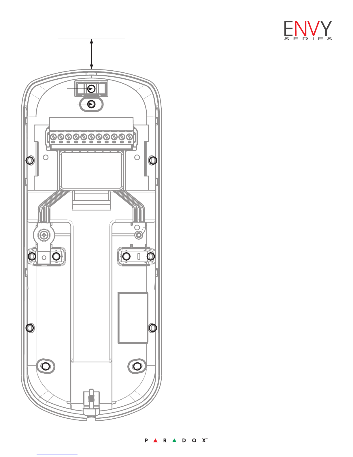
Important: Keep a 20 mm/0.80 in
clearance from the top of the unit’s
plastic casing to the ceiling or
object placed above the unit.
Legend
L
W1
R+ B- GRN YEL TMP NC1 C1 NO1 NC2 COM NC3
Wiring
C1 C1
Entry
Hole
L – Level
W1 – Wall installation
W2 – Wall Tamper Installation
C1 – Corner-Mount Installation
C2 – Corner-Mount Tamper Installation
Installation Steps
1. Loosen the tamper screw found at the
bottom of the unit.
2. Separate the back cover from the unit.
3. Drill or punch out the appropriate knock-out holes
for either a wall or corner installation, refer to the
installation legend above.
4. Make sure to allow for 20 mm/0.80 in of space
between the top of the unit and a ceiling or
object found above it.
5. Mark your selected location using the back cover
of the unit as a template.
W2C2
C1
W1 W1
W2 C2
C1
6. Drill holes into the wall surface.
7. Thread the wires through the wire entry hole.
8. Secure the back cover of the unit to the wall
surface using mounting screws appropriate for
the specific installation.
9. Slide the front section of the unit into place
on the back cover of the unit. If the wires are
connected to electricity, then the power up
sequence will automatically start.
10. Ensure that the outer rim of the unit is tightly
joined, so that waterproof casing is not
compromised.
11. While the tamper screw at the bottom of the unit is
open, begin the power up process and access the
menus to change any sensitivity or other settings,
then press OK to save the altered settings.
12. Tightly close the tamper screw found at the
bottom of unit and put the detector into
operation mode.
For the complete manual visit www.paradox.com.
1 NVX80-EQ02
06/2013
Page 2
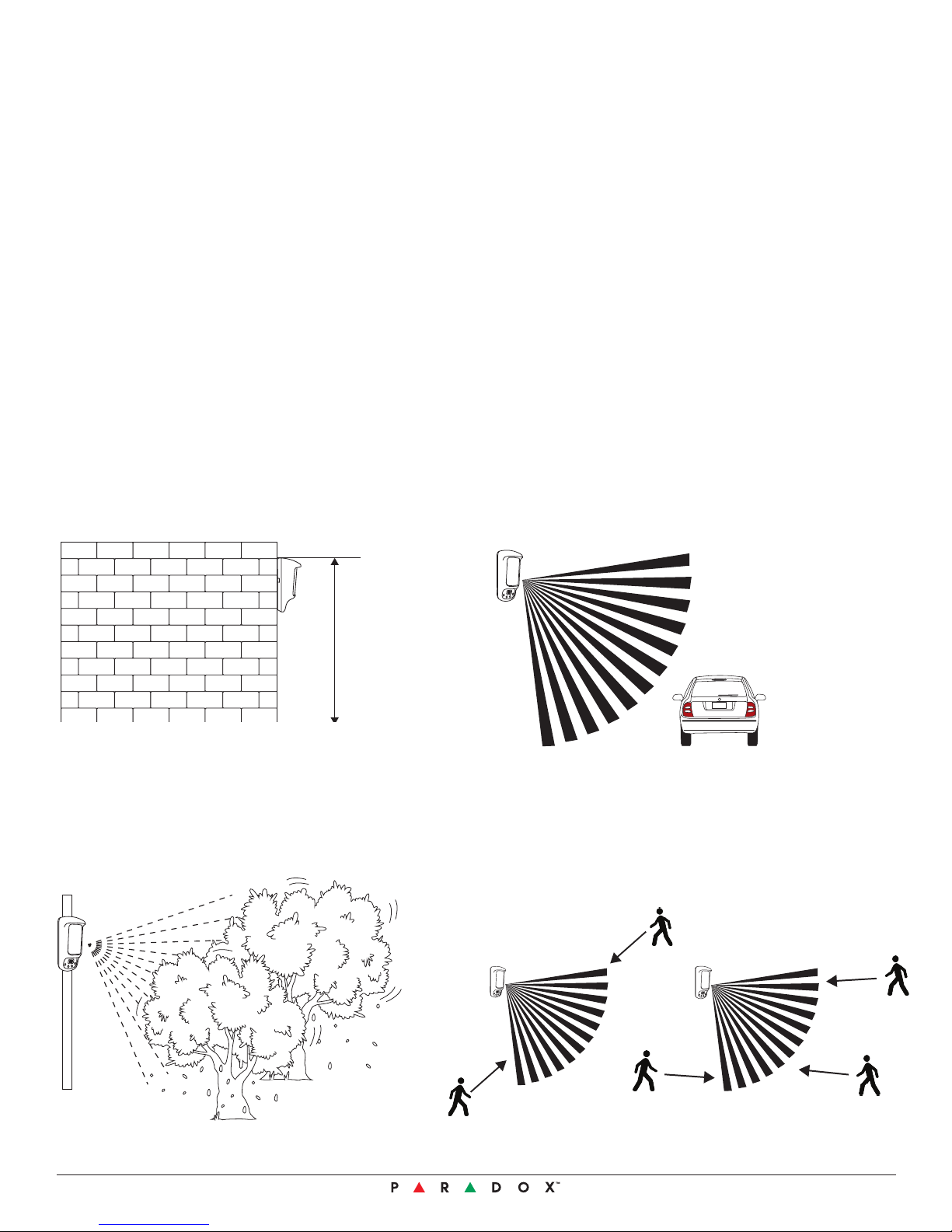
Installation Do’s and Don’ts
Do
- Do ensure that the unit’s detection beams are perpendicular to the anticipated movement.
- Keep a minimum distance between adjoining NVX80 detectors to prevent MW cross interference, see the
beam pattern diagram.
- Do place the unit under a roof, awning, or use our all-weather cover for an outdoor installation.
- Do install the within the suggested range: installing the unit lower than 2.5 m/8 ft 2 in may compromise the
Pet Immunity capability, installing over 3.0 m/9 ft 8 in may require use of our swivel bracket adjusted downward
shifting the Pet Immunity beam and neutralizing the creep zone. Installing the unit over 3.0 m/9 ft 8 in does not
affect the creep zone.
Don’t
- Don’t direct the unit’s beams into swaying trees or bushes.
- Don’t place the detector facing direct sunlight or near a heat source , as it might interfere with the Active IR anti-mask feature.
- Don’t place any objects, such as shelves, ledges or plants, below the unit.
- Don’t place any reflective objects within 2m/6ft 6in of the unit, as this may interfere with the MW anti-mask capabilities.
Mounting Considerations
The optimal installation height for the NVX80 is
2.5 m to 3.0 m (8 ft 2 in to 10 ft).
2.5 m - 3.0 m
(8'2'' - 10')
Avoid installing the detector near moving objects
(e.g., swaying trees, bushes, etc.).
whether
If the installation site is near heavy traffic or objects
beyond the required detection range, adjust the MW
sensitivity and/or tilt the detector down.
In order to maximize detection efficiency, choose a
location that is most likely to intercept intruders moving
across the coverage area at a 45 degree angle.
NVX80-EQ02
06/2013
2
Page 3
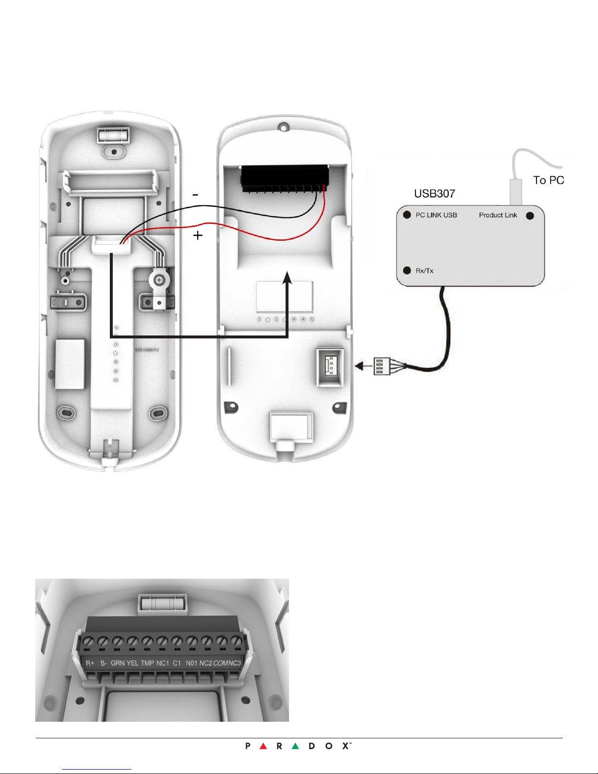
Firmware Upgrades
Use the diagram below to upload firmware upgrades.
Connecting to the Bus
Connecting to the Digiplex bus is quite straight forward. Insert the wires into their respective slots Red (R+), Black (B-),
Green (GRN) and Yellow (YEL).
3 NVX80-EQ02
06/2013
Page 4

Menu Overview
Menu
SeeTrue
PIR
MW
MW and
MW anti Mask
IR Anti-M ask
Wall Tamper
Outpu ts
Diagnostics
Settings
About
Language
Idle
Secure
Ste rile
PIR Sens itivity - 1 2 3 4 5 +
XXX
Norm al
Medium
Hig h
Off
Small Pet
Large Pet
-Off 1 2 3 4 5 +
- 1 2 3 4 5 +
- 1 2 3 4 5 +
Indoor
Outdoor
30 sec
60 sec
120 sec
AM Calib ration
Code
Alarm
Tamper
IR Anti-Mask
MW Ant i-Mask
PIR
Microwave
Clean Lens
Trouble
Creep Zone
N.O.
N.C.
N.O.
N.C.
Test A ll
Test P IR
Test MW
Test Anti -Mask
Test BU S
Multi-choice
No
Yes
No
Yes
No
Yes
Orange
Green
Yellow
Blue
- 1 2 3 4 5 +
Secur ity Level
Pet Immu nity
Creep Zone
Test PIR
Sensitivity
MW AM Dist ance
Test MW
Mode
Response Time
Calibrate
Test AM
AM CODE
Enable
Disable
Relay 1 Functi on
Relay 2 Functi on
Relay 2 Logic
Relay 3 Functi on
Relay 3 Logic
Show event(s)
Restore Setting.
Save Settings
Reset
Menu Color
Brightness
Version #
Date
Serial #
English
Multi -choice
Multi -choice
1.07
10.6.2013
270004E3
Sensitivity
Creep Zone
Off
Alarm
Tamper
IR An ti-Mask
MW Anti -Mask
PIR
Micro wave
Clean Lens
Trouble
Creep Zone
Multi-Choice
Tests IR Antimask and MW ant imask
Tests Voltage and Digip lex Communication
Orange
Green
Yellow
Blue
Bright ness
Sensitivity
MW AM Distance
MW Ant i-Mask
Alarm
Pre Alarm
Trouble
Anti Mas k
Alarm
Tamper
IR Anti-Mask
PIR
Microwave
Clean Lens
Trouble
Creep Zone
SensitivitySensitivity
Applies to IR Antimask and MW an timask
Legend
FUTURE USE
Filename: NVX80 Menus FW v1.07.vsd
DEFAULT SETTINGS
Tabs: Overview
Modified: June 11, 2013 4:59:02 PM
DEFAULT SETTINGS
NVX80-EQ02
06/2013
4
 Loading...