

Page 1
LCD Keypad V1.1
DGP2-641
Reference and Installation Manual
Page 2

Page 3

Tabl e Of Con t ents
Introduction.................. ................................... 3
Specifications ...................................................... 3
Installation .................... ................... ................ 4
Connecting Keypad Zones .................................. 4
Programmable Output ......................................... 5
Programming .................................. ................ 6
Entering Module Programming Mode.................. 6
Programming Methods ........................................ 7
Feat ure Select Program ming .... .. .... .... .... .... .... .... .... 7
Dec imal Program ming ...... .. .. .. .. .. .. .. .. .. .. .. .. .. .. .. .... .. .. 7
Module Broadcast ............................................... 7
Memory Key ........................................................ 8
Download Contents of Memory Key to Keypad... 8
Copy the Keypad Contents to the Memory Key .. 9
System Options .............................. .............. 11
Partition Assignment ......................................... 11
Display Access Code Entry............................... 11
Display Exit Delay Timer ................................... 11
Display Entry Delay Timer................................. 12
Confidential Mode ............................................. 12
Page 4

Confidential Mode Timer ................................... 13
Time Display Option.......................................... 14
Muting................................................................ 14
Beep on Exit Delay ............................................ 14
Chime on Zone Closure..................................... 15
Beep on Trouble ................................................ 15
Keypad Tamper Enable..................................... 16
Communication Bus Voltmeter .......................... 16
Programmable Output Options ........ ........... 18
PGM State ......................................................... 18
PGM Deactivation Mode.................................... 18
PGM Base Time ................................................ 19
PGM Override .................................................... 19
PGM Timer ........................................................ 19
PGM Activation Event........................................ 20
PGM Deactivation Event ................................... 20
Message Programming ................................ 22
Special Function Keys ....................................... 23
Page 5

1.0 Introduction
Thank you for choosing Paradox Security Systems. Digiplex/
DigiplexNE Security System s are advanced technology security
systems tha t will provide reliable security protection and powe rful
features that are easy to use. The elegant and user-friendly LCD
Keypad will allow easy a ccess to t he security system's functions
and information at the touch of a button. Since all programm ing
is accomplished through the keypad, please read this manual
carefully.
1.1 Specifications
Power input: 12 to 16 Vd c, 8 0mA maxi mum
PGM current limit : 50 mA
Number of inputs: 1
Po we r indica tion: Ye l lo w LE D on
Locate i ndicati on:
Bu s fau l t ind ication : Red an d ye llo w LED s f las h al tern ate ly
An ti -ta mp er swi tc h: Ye s (also used to deact iva te loc at e)
LCD: Super Twisted Nematic display (STN), wide
Compatibility: Any Digiplex/Digip lexNE Control Panel
Green a nd yell ow LEDs fl ash simul taneousl y
vi ew i ng ang le, 2 line s of 1 6 chara cter s, b ac kli gh t
an d co ntr a st ad j usta bl e
Digiplex/DigiplexNE LCD Keypad 3n
Page 6

2.0 Installation
The LCD keypad (DG2P-641) is connected to the c ontrol panel's
communication bus in a star and/or daisy chain configuration.
The 4-wire communication bus provides power and two-w ay
communication between the control panel and all modules
connected to it. Connect the four terminals labeled red, black,
green and yellow of each keypad to the corresponding terminals
on the control panel (refer to Figure 2.1 on page 5). Refer to the
Digiple x or DigiplexNE Reference & Installation Manual for the
maximum allowable installation distance from the control panel.
2.1 Connecting Keypad Zones
Each keypad has one traditional hardwired input terminal,
allowing you to connect one detector or door contact directly to
the keypad. For example, a door contact located at the entry
point of an establishment can be wired directly to the input
terminal of the entry point keypad instead of wiring the door
contact all the w ay to the control panel.
Connect the device to the keypad's input terminal as shown in
Figure 2.1 on page 5. In order to communicate its status to the
control panel, devices connected to the keypad's input terminal
must be ass igned to a zone in the control panel and the zone's
parameters must be defined. For more information on zone
assignment, please refer to the Digiplex or DigiplexNE
Reference & Installation Manual. Please note that even w ith the
ATZ (zone doubling) feature enabled, the key pad supports only
one detection device.
4 Refer ence & Installation Manual
Page 7
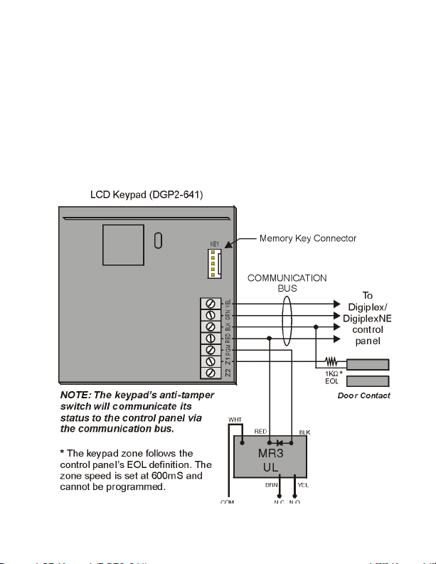
2.2 Programm able O utput
Each keypad has one on-board PGM. A PGM is a programmable
output that toggles to its opposite state (i.e. a normally open
PGM will close) when a specific event has occurred in the
system (refe r to section 5.0 on pa ge 17) . Upon act ivation, the
PGM can provide 50mA to any device connected to it. If the
current drawn is to exceed the current limit, a relay should be
connected to the PGM as shown in Figure 2.1.
Figure 2.1: Connecting the Keypa d and Keypad Zone
Digiplex /DigiplexNE LCD Keypad 5n
Page 8

3.0 Programming
To program the DGP2-641 keypad, enter Module Programming
Mode and then enter the desired section followed by the required
data. When programming the keypad, use the k eypad’s
programming sheets (found in the Digiplex/DigiplexNE Modules’
Programming Guide) to keep track of which sections were
programmed and how. We strongly recommend you read this
entire manual before you begin programming.
The LC D keypad can also be programmed using the WinL oad
Security Sy stem Management Software. For more information,
refer to the WinLoad instructions or visit our Web site at
www.parad ox.ca.
3.1 Entering Module Programming Mode
The ke ypad, like all o the r modu les in the syst em , is p rogra mmed
through the control panel. To do so, you must first enter Module
Programming Mode:
1. F r o m No r m a l Mo de pre ss an d h ol d the [0] key.
2. E nt er th e [INSTALLE R CODE] (by default 000000).
3. Enter se ction [953] (DGP-48) / [4003] (DGP-NE96).
4. E nt er th e ke yp ad ’ s 8 - d igi t [SERIAL NUMBER].
5. Enter the 3-digit [SECTION] you want to program.
6. Enter the required [DATA].
The control pan el will then redirec t all pro gramming to t he
selected keypad. Every time the [CL E AR ] key is pressed it will
rev ert to the preceding step, unless entering in data in whic h
6 Refer ence & Installation Manual
Page 9

case it will erase the current data entry. Please note th at the
se rial nu mb er is lo ca te d o n th e ke yp ad ' s P C bo a rd or en te r
section [000] in Step 3 to view the keypad’s serial number.
3.2 Programming Methods
The following methods can be used when programming the
keyp ad:
3.2.1 F eature Select Programming
Some sections are programmed by enabling or disabling
options. Within the sections, numbers from [1] to [8 ]
represent a spec ific key pad option. Press the key
corresponding to the desired option and the digit will
appear in the display. This means the option is enabled.
Press the key again to remove the digit from the display
thereby disabling the option. Press [ENTER] when options
are set.
3.2.2 Decimal Prog ramming
Some sections require that a decim al value be entered. In
this method, any digit from 000 to 255 can be entered.
3.3 Module Broadcast
The control panel’s Module Broadcast feature can be used to
copy the contents of one keypad to one or more keypads.
1. From Normal Mode press and hold the [0] ke y.
2. E nt er [IN STALLE R CODE] (default: 000000).
3. Enter se ction [954] (DGP-48) / [4004] (DGP-NE96).
4. E nt er th e [SERIAL #] of the source keypad. T he source is
the programmed keypad whose data you want to copy to
Digiplex /DigiplexNE LCD Keypad 7n
Page 10

other keyp ads.
5. E nt er th e [SERIAL #] of the destination keypads. The
destination is the keypad(s) you want to program with the
source’s data. If you want to program more than one
keypad with the source’s data, enter the serial numbers
of the keypads one at a time.
6. O nc e yo u ha ve en te r e d th e se r i al nu m b ers o f the
keypads you want to program, press the [ACC] key.
3.4 Memory Key
SECTION S [510] AND [520]
Download information to and from an LCD keypad using the
memory key (PMC-3).
Section [510] = Download all from the memory key (LCD
keyp ad s ec tions [001] to [396 ] and all
messages) to the LCD keypad.
Sect ion [520] = Copy the LCD keypad sections [0 01] to [396]
and all messages to the memory key.
Only the PMC-3 memory key will function with the
LCD keypad.
3.5 Download Contents of Memory Key to Keypad
SECTION [510]
1. Inse rt the memory key into th e keypad ’s conn ector
labelled “KE Y” (refer to Figure 2.1 on page 5).
2. To download the contents of the memory key, enter the
8 Refer ence & Installation Manual
Page 11

keypad’s programming mode and enter section [510].
3. When the keypad emits a confirmation beep, wait 5
seconds and remove the memory key after the second
confirmation beep.
3.6 Copy the Keypad Con tents to t he Mem ory K ey
SECTION [520]
1. Insert the memory key onto the key pad’s connector
labelled “KE Y” (refer to Figure 2.1 on page 5). Ensure that
the write protect jumper is ON (refer to Figure 3.1).
2. To copy the contents to the memory key, enter the
keypad’s programming mode and enter section [520].
3. After the confirmation beep, wait 5 seconds and remove
the memory key after the s econd confirmation beep. Set
the memory key’s jumper to OFF if you do not wish to
accidentally overwrite its contents (refer to Figure 3.1).
Figure 3.1: PMC-3 Jumper Settings
Digiplex /DigiplexNE LCD Keypad 9n
Page 12

4.0 System Options
4.1 Partition Assignm ent
SECTION [ 0 01 ]: O PT ION S [1] TO [8 ]
Each keypad in the system can be ass igned to one or more
par tit ion s. In s ec tion [0 01], optio ns [1] to [8] represent partitions
1 through 8 respectively. To assign the key pad to a partition,
simply enable the option that corresponds to the desired
partition. By default, partitions 1 to 8 are enabled.
Se ction [001] op ti ons [5] to [8] can onl y be used if the
keypad is connected to a DigiplexNE (DGP-NE96)
contr ol pan el.
4.2 Display Acces s Code Entry
SECTION [ 0 03 ]: O PT ION [1]
The digits of the User Access Codes c an be displayed on the
LCD screen when they are entered.
O
ption [1] OFF = Digits are replaced by a * (default).
Optio n [1] ON = Acc ess Cod e digits will be dis played.
4.3 Display Exit Delay Time r
SECTION [ 0 03 ]: O PT ION [2]
Based on the user's needs, an Exit Delay Timer will be
programmed to provide the user time to exit the partition before
the system is armed. The Exit Delay Timer's countdown can be
displayed on the LCD screen.
10 R eference & Installation Manual
Page 13

Optio n [2] OFF= Will not display Exit De lay timer (default).
Optio n [2] ON= LCD screen will dis play Exit Delay t imer.
4.4 Display Entry Delay Time r
SECTION [ 0 03 ]: O PT ION [3]
Based on the user's needs, an Entry Delay Timer will be
programmed to provide the user time to enter their User Access
Code before the alarm is triggered. The Entry Delay Tim er's
countdown can be displayed on the LCD screen.
Optio n [3] OFF= Will not display the Entry Delay Timer
(default).
Optio n [3] ON= LCD screen will dis play Entry Delay Timer.
4.5 Confidential Mode
SECTION [ 0 03 ]: O PT ION S [4] AND [5]
If the Confidential Mode is enabled and no actions are performed
on t he keypad for a period of tim e, the LCD screen will appear as
shown in Figure 4.1 (page 12) and the “AC” and “STATUS” LED
will be off until either a button is pressed or an access code is
entered. The period of time in which no action is performed is
defined by the Confidential Mode Timer (005-255 seconds; refer
to section section 4.6 on page 12 on page 12). Confidential
Mode is activated by enabling option [4 ] . Optio n [5] regulates
whether the LCD s creen will be activated at the touch of a button
or only when an access code is entered.
On ce th e LCD scr e e n i s ac t iva te d ( by cod e or bu tt on ) , N o rm al
Digiplex/DigiplexNE LCD Keypad 11n
Page 14

Mode w ill appear and display the date and time as shown in
Figure 4.1 on page 12. The status of the areas, the open zones
for every area the keypad is assigned, the Alarm Memory
Display (if necessary) and the Trouble Display (if neces sary. See
Digiple x or DigiplexNE User Manual) will also sc roll on the LCD
screen.
Optio n [4] OFF = N ormal Mode (default).
Optio n [4] ON = Confidential Mode.
Optio n [5] OFF = LCD screen activated by entering an access
code (default).
Optio n [5] ON = LCD screen activated by pressing a button
Figure 4. 1: LCD Screen
4.6 Confidential Mode Timer
SECTION [007]
Section [007] determines the amount of time without action
before the keypad enters Confidential Mode. For more
information on Confidential Mode, refer to “Confidential Mode” on
page 11. The Confidential Mode Timer can be set from 005
seconds to 255 seconds. Default: 120 seconds.
12 R eference & Installation Manual
Page 15

4.7 Time Display Option
SECTION [ 0 03 ]: O PT ION [8]
Th e LC D ke yp a d co m e s wit h a tim e d isp lay opt i on th at ca n
display the date as year/month/day or as day/month/year.
Optio n [8] OFF = Date displayed as y y/mm/dd (default).
Optio n [8] ON = Date displayed as dd/mm/yy.
4.8 Muting
SECTION [ 0 04 ]: O PT ION [1]
The keypad can be programmed not to emit audible sounds,
inc luding Chimed z ones. Du ring Muting, the key pad will on ly
emit the Confirmation Beep, Rejection Beep, and beep when a
button is pressed.
Optio n [1] OFF = Audible sounds (default).
Optio n [1] ON = Mute.
4.9 Beep on Exit Delay
SECTION [ 0 04 ]: O PT ION [2]
The keypad can beep once every second during the Exit Delay
Timer. D uring the final 10 seconds, it will beep more rapidly to
provide a final warning before the area is armed.
Optio n [2] OFF= Exit Delay beep disabled.
Optio n [2] ON= Exit Delay beep enabled (default).
Digiplex/DigiplexNE LCD Keypad 13n
Page 16

4.10 Chime on Zone Closure
SECTION [ 0 04 ]: O PT ION [4]
During the Chime Zone Time Period that the user sets, the
keypad can emit an intermittent beep whenever a zone w ith the
Chime feature enabled closes (see D igiplex or DigiplexNE Us er
Manual for details on Chime Zones). If the user does not set the
Chime Zone Time Period and this option is enabled, the Chime
Zones will a lways beep upon closure.
Optio n [4] OFF = C hime on Zone Closure disabled (default).
Optio n [4] ON = Chime on Zone Closure enabled.
4.11 Beep on Trouble
SECTION [ 0 05 ]: O PT ION S [1] TO [4 ]
Potential troubles have been sorted into groups. With these
opt ions enabled, the keypad will emit an intermittent beep tone
whenever a trouble condition from the Trouble Groups occurs in
the system. The int ermittent beep will remain activated until the
user enters the Trouble Display or if the trouble is resolved. For a
list of the troubles, see the D igiplex or DigiplexNE Reference and
Installation Manual. The intermittent beep will be re-initialized
whenever the trouble condition re-occurs.
O
ption [1] OFF = Beep disabled: System Troubles and Clock
Loss (default).
Optio n [1] ON = Beep enabled: System Troubles and Clock
Lo ss.
14 R eference & Installation Manual
Page 17

Optio n [2] OFF = Beep disabled: Communicator Troubles
(default).
Optio n [2] ON = Beep enabled: Communicator Troubles.
Optio n [3] OFF = Beep disabled: Module and Bus Troubles
(default).
Optio n [3] ON = Beep enabled: Module and Bus Troubles.
Optio n [4] OFF = Beep disabled: all Zone Troubles (default).
Optio n [4] ON = Beep enabled: all Zone Troubles.
4.12 Key pa d Tam p er E nable
SECTION [ 0 06 ]: O PT ION [5]
When tamper is enabled and the keypad's on-board anti-tamper
switc h is triggered, the keypad will send a Tamper report to the
control panel via the communication bus.
Optio n [5] OFF = Keypad's tamper is disabled (default).
Optio n [5] ON = Keypad's tamper is enabled.
4.13 Communication Bus Voltmeter
The Communication Bus Voltmeter provides a real-time display
of the voltage so you can v erify if the bus is supplying sufficient
power at the keypad’s location. The readings will appear on the
LCD screen. A reading of 10.5V indicates that the voltage is too
low. This may occur when too many modules are connected to
the bus, a m odule is installed too far from the panel or if the
Digiplex/DigiplexNE LCD Keypad 15n
Page 18

system is running on the battery. In some cases adding an
external power supply may correct the situation.
1. F r o m No r m a l Mo de pre ss an d h ol d the [0] key.
2. E nt er th e [INSTALLE R CODE] (by default 000000).
3. P res s [ACC].
The voltage may drop during the control panel battery
test.
16 R eference & Installation Manual
Page 19

5.0 Programmable Output Options
5.1 PGM State
SECTION [ 0 06 ]: O PT ION [1]
The keypad's on-board PGM can be s et as normally open or
normally closed. When an open PGM is activated, it will close the
circuit from ground and enable any devices connected to it.
When a c losed P GM is activated, it will op en the circ uit and
disable any devices connected to it. When the PGM Activation
Event occurs (see section 5.6), the PGM will switch to its
opposite state (i.e. open to closed or closed to open).
Optio n [1] OFF= PGM is Normally Open (default).
Optio n [1] ON= PGM is Normally C losed.
The PGM can prov ide 50mA to any device connected to
it.
5.2 PGM Deactiva tion Mode
SECTION [ 0 06 ]: O PT ION [2]
If the keypad is in PGM Timed Mode, the keypad's on-board
PGM will be deactivated according to the PGM Timer (see
section 5.5 below) instead of the PGM Deactivation Event.
Optio n [2] O F F = D ea c t iv at e s o n P GM D e ac tiva ti o n Ev en t
(default).
Optio n [2] ON = PG M will deactivate acc ording to the PGM
Timer.
Digiplex/DigiplexNE LCD Keypad 17n
Page 20

5.3 PGM Base Time
SECTION [ 0 06 ]: O PT ION [3]
If the keypad's on-board PGM is set in PGM Timed Mode (see
section 5.2 on page 17) you must define whether the value
programmed in section [008] is in minutes or seconds.
Optio n [3] OFF = PG M Base Time is 1 second (default).
Optio n [3] ON = PGM Base Time is 1 minute.
5.4 PGM Override
SECTION [ 0 06 ]: O PT ION [4]
When the PGM override is enabled, the keypad's on-board PGM
will ignore PGM Activation Events (section section 5.6 on page
19, page 19), PGM Deactivation Events (section section 5.7 on
page 19, page 19), and PG M Timers (sec tion section 5.5 on
page 18, page 18). It will remain in its normal state until the PGM
Override is disabled. This option may be used to test the PGM
connections.
Optio n [4] OFF = PGM Override disabled (default).
Optio n [4] ON = PGM Override enabled.
5.5 PGM Timer
SECTION [008]
If the keypad's on-board PGM is in PGM Timed M ode, the value
programmed in section [008] represents how long the PGM w ill
remain in its opposite state (see section 5.1 on page 17) after
being activated. To program the timer, enter a 3-digit decimal
18 R eference & Installation Manual
Page 21

value (000 to 255) in section [008]. The 3-digit value will be
multiplied by the PGM Base Time of 1 second or 1 minute (see
section 5.3 above). Default: 5 seconds.
5.6 PGM Activation Event
SECTION S [009] TO [012]
The PGM Activation Event determines which event will activate
the keypad's on-board PGM output. The EVENT GRO U P specifies
the event, the FE ATU RE GROUP identifies the s ource, and the
START # and END # sets the range within the Feature Group. Use
the PGM Programming Table in the Digiple x/DigiplexNE
Modules’ Programming Guide to program the keypad’s PGM
Activation Event.
Enter the sec tions that correspond to the EVENT GRO UP, FEATURE
GROUP, START # and END # of the PGM and enter the required
da ta .
Ev ent Group Feature Gr oup Start # End #
PGM [009] [010] [011] [012]
5.7 PGM Deactiva tion Eve nt
SECTION S [013] TO [016]
If the PGM Deac tivation Option (section sec tion 5.2 on page 17
on pa g e 17 ) is se t to fo llo w th e P G M De a ctiva tion eve n t, the
PGM will return to its normal state when the event programmed
in sections [013] to [016] occurs. The EVENT GRO U P specifies the
ev ent , t he FEATURE GROU P identifies the source, and the START #
and END # sets the range within the Feature Group. Use the PGM
Digiplex/DigiplexNE LCD Keypad 19n
Page 22

Programming Table in the Digiplex/DigiplexNE Modules’
Programming Guide t o pro g ra m th e ke yp ad ’ s P G M Acti v at ion
Ev ent.
Enter the sec tions that correspond to the EVENT GRO UP, FEATURE
GROUP, START # and END # of the PGM and enter the required
da ta .
Event Group Feature Group Start # End #
PGM [013] [014] [015] [016]
20 R eference & Installation Manual
Page 23

6.0 Message Programming
SECTION S [101] TO [1 4 8 ], [20 0] TO [204], and [301] TO [396]
Each section contains one message with a maximum of 16
characters. For more details and to record any changes, use the
Digiple x/DigiplexNE Modules’ Programming Guide.
The DigiplexNE control panel has up to 8 partitions, 96
zones and up to 999 user codes. The LCD keypad only
allows you to program the messages for up to 4
partitions, 48 zones and 96 user codes. The rest of the
messages can be programmed directly into the
DigiplexNE control panel. Refer to the DigiplexNE
Reference & Installation Manual and to the DigiplexNE
Programming Guide for more details.
Section [101] to [148] = “Zone 01” to “Zone 48” respectively
Sect ion [200] = “Paradox Family”
Sect ion [201] to [204] = “First Area”, “Second Area”, “Third
Area”, and “Fourth Area” respectively
Sect ion [301] to [396] = “Code 01” to “Code 96” respectively
After entering the section corresponding to the desired message,
use the Message Programming Keys (refer to Table 6.1 on
page 22) and the Special Function Keys on page 22 to change
the message to suit your installation needs. For example, section
[101] “ZONE 01” c an be changed to “FRONT DOOR”.
Digiplex/DigiplexNE LCD Keypad 21n
Page 24

Table 6.1: Message Programming Keys
Key
Press Key
Once
Press Key
Twice
Press Key
Th ree Times
[1] ABC
[2] DEF
[3] GH I
[4] JKL
[5] MNO
[6] PQR
[7] STU
[8] VWX
[9] YZ
6.1 Special Function Keys
[STAY ] - In sert Spac e
Pressing the [STAY] key ins erts a blank space in the current
cursor posit ion.
[FORCE] - Delete
Pressing the [FORCE] key will d elete the character or blank space
found at the current cursor position.
[ARM] - Delete Until the End
Pressing the [ARM] key w ill delete all characters and spaces to
the right of the cursor and at the curs or's position.
[DISARM] - Numeric Keys / Alphanumeric Keys
Ev ery tim e the [DISARM] key is pressed it will toggle numeric keys
to alphanumeric keys and vice versa. Numeric: Keys [0] to [9]
represent num bers 0 to 9.
22 R eference & Installation Manual
Page 25

[BYP] - Lower Case / Upper Case
Ev ery tim e the [BYP] key is pressed it w ill toggle the case setting
from lower to upper cas e and vice versa.
[ME M] - Special Characters
Af ter pr es si ng the [ME M ] key, the cursor will t urn into a f lashing
black square. Using section 6.1 on page 24 on the following
page, enter the 3-digit number that represents the desired
symbol.
Digiplex/DigiplexNE LCD Keypad 23n
Page 26

Table 6. 1: Spe cial Characters Catalog
24 R eference & Installation Manual
Page 27

Wa rr ant y
The Seller warrants its products to be free from defects in
materials and work manship under normal use for a period of one
year. Except as specifically stated herein, all express or implied
warranties whatsoever, statutory or otherwise, including without
limitation, any implied warranty of merchantability and fitness for
a particular purpose, are expressly excluded. Because Seller
does not install or connect the products and because the
produc ts may be used in conjunction with products not
manufactured by Seller, Seller cannot guarantee the
performanc e of the se curity system. Selle r oblig ation and liability
under this warranty is expressly limited to repairing or replacing,
at Seller's option, any product not meeting the specifications. In
no event shall the Seller be liable to the buyer or any other
person for any loss or damages whether direct or indirect or
consequential or incidental, including without limitation, any
damages for lost profits, stolen goods, or claims by any other
party caused by defective goods or otherwise arising from the
improper, incorrect, or otherwise faulty installation or use of the
merchandise sold.
© 2002 Paradox Security Sy stems Ltd.
Winload, Digiplex and DigiplexNE are trademark s of Paradox
Security Sy stems
Digiplex/DigiplexNE LCD Keypad 25n
Page 28

Notes
26 R eference & Installation Manual
Page 29

Page 30

Page 31

Page 32

PRINTED IN C ANADA
-
01/ 2003 DG P26 41-EI08
 Loading...