

Page 1
KLEDEU03.fm Page -1 Friday, May 4, 2001 11:25 AM
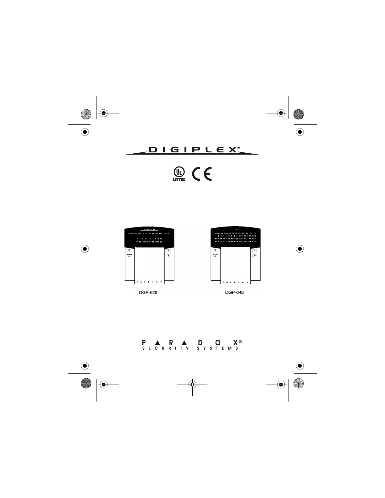
Digiplex LED Keypads
User’s Manual
Page 2
KLEDEU03.fm Page 0 Friday, May 4, 2001 11:25 AM
Page 3
KLEDEU03.fm Page 1 Friday, May 4, 2001 11:25 AM
TABLE OF CONTENTS
1.0 INTRODUCTION ........................................................4
1.1 Legend ..................................................................4
2.0 BASIC OPERATION ..................................................4
2.1 Auditory Feedback (Beep Tones) .........................5
2.2 Keypad Indicator Lights ........................................6
2.3 LED Keypads ........................................................6
2.4 Partitioned System ................................................8
2.5 Area Status Display ..............................................8
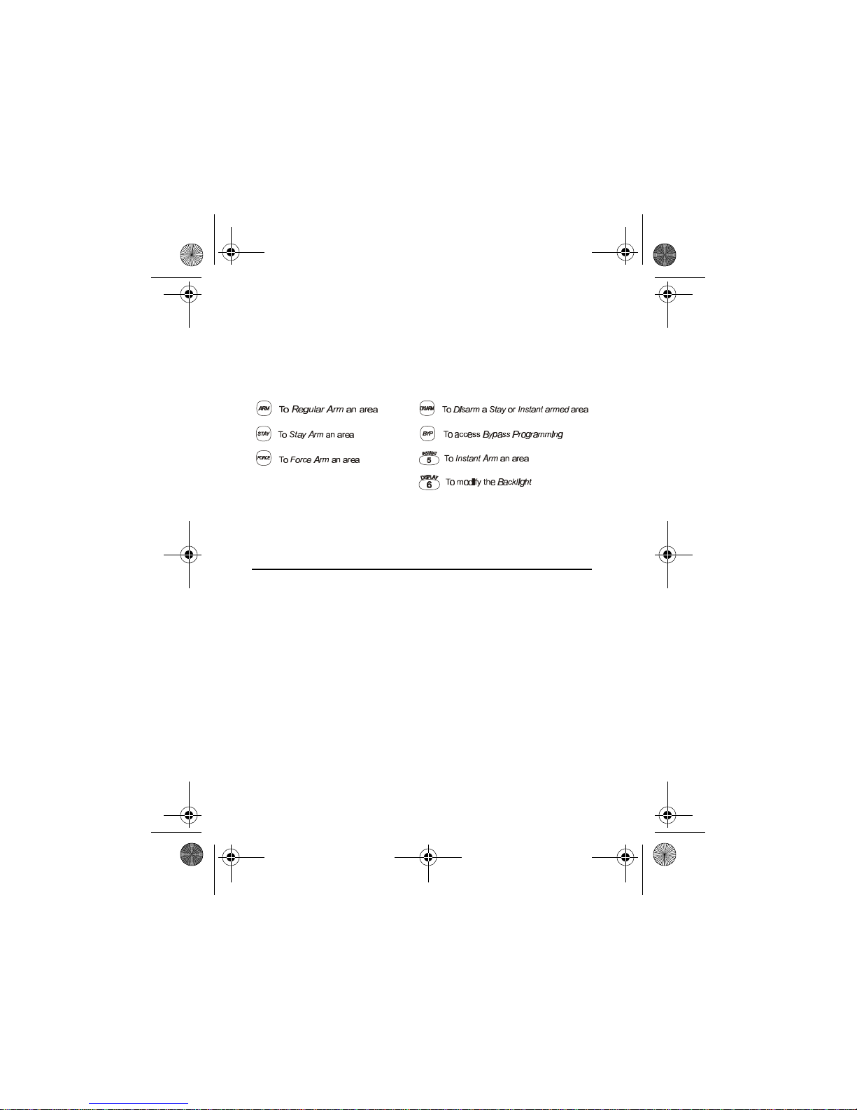
3.0 ARMING ....................................................................10
3.1 Exit Delay Timer ...................................................10
3.2 Regular Arming ....................................................10
3.3 Stay Arming .........................................................11
3.4 Instant Arming ......................................................12
3.5 Force Arming .......................................................13
3.6 One-Touch Buttons ..............................................14
3.7 Keyswitch Arming ................................................15
3.8 Auto-Arming .........................................................16
3.9 Bypass Programming ...........................................17
4.0 DISARMING ..............................................................20
4.1 Entry Delay Timer ................................................20
4.2 Disarming an Armed System ...............................20
4.3 Alarm Memory Display .........................................22
5.0 ACCESS CODES ......................................................22
Page 4

KLEDEU03.fm Page 2 Friday, May 4, 2001 11:25 AM
5.1 System Master Code (default 123456) ................23
5.2 User Access Codes .............................................24
5.3 User Options ....................................................... 26
5.4 Area Assignment ................................................. 28
5.5 Erasing Access codes ......................................... 29
6.0 TROUBLE DISPLAY ................................................29
7.0 ADDITIONAL FEATURES ........................................31
7.1 Programmable Outputs (PGMs) .......................... 31
7.2 Set Time and Date .............................................. 32
7.3 Panic Alarms .......................................................33
7.4 Programming Chime Zones ................................34
7.5 Quick Function Buttons .......................................36
8.0 FIRE AND BURGLAR ALARMS .............................. 37
8.1 Standard Fire Zone ............................................. 37
8.2 Delayed Fire Zone ............................................... 38
8.3 Fire Safety Tips ...................................................40
8.4 Minimizing Home Fire Hazards ........................... 41
8.5 Burglar Alarm ......................................................41
9.0 TESTING AND MAINTENANCE ..............................42
9.1 Burglar Alarm Testing ..........................................42
9.2 Fire Alarm Testing ............................................... 43
9.3 System Maintenance ........................................... 43
9.4 System Test ........................................................ 43
10.0 SYSTEM CHECKLIST ............................................ 44
Page 5

KLEDEU03.fm Page 3 Friday, May 4, 2001 11:25 AM
10.1 Zone Description ................................................44
10.2 Special Buttons and Features ............................46
10.3 User Access Codes ...........................................48
Page 6
KLEDEU03.fm Page 4 Friday, May 4, 2001 11:25 AM
1.0 INTRODUCTION
Your Security System is an advanced technology security
system that will provide you with reliable security protection and
powerful features that are easy to use.
Since you will communicate your instructions to your system
through the keypad, please read this manual carefully and have
your installer explain basic system operation.
1.1 LEGEND
Indicates a warning or an important note.
Indicates useful information or tip.
[WORD]
[NUMBER] Indicates information that must be entered on the keypad.
Italics Indicates references to features, options or sections.
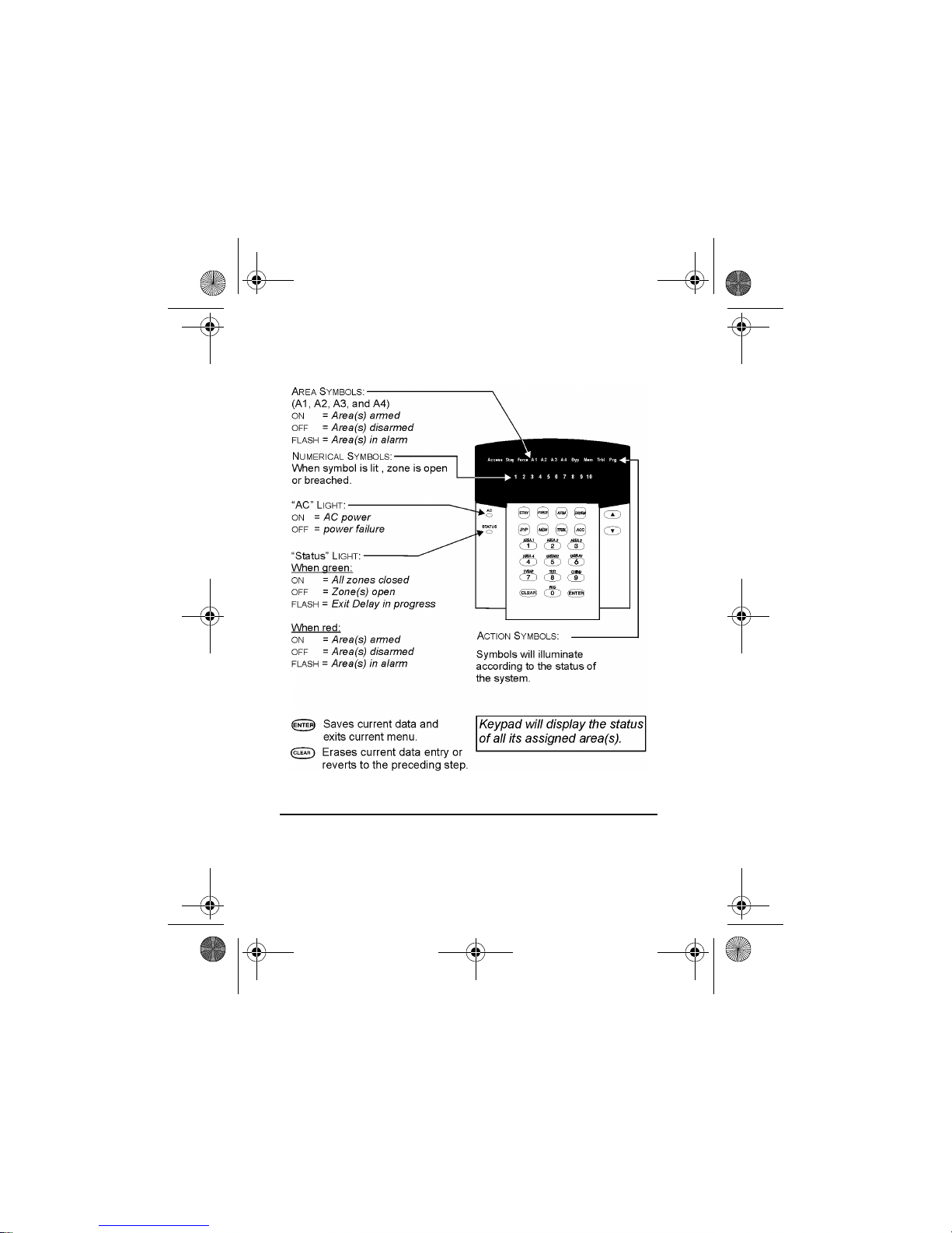
2.0 BASIC OPERATION
Your security system communicates by illuminating the “AC”
Light, the “Status” Light, and the various symbols on the screen
as explained in Figure 2-1.
4 User’s Manual
Page 7
KLEDEU03.fm Page 5 Friday, May 4, 2001 11:25 AM
Figure 2-1: Basic Overview
2.1 AUDITORY FEEDBACK (BEEP TONES)
When you enter information on the keypad, the keypad will guide
LED Keypads 5
Page 8
KLEDEU03.fm Page 6 Friday, May 4, 2001 11:25 AM
you with beep tones to communicate acceptance or rejection of
your entries.
Confirmation Beep: When an operation (i.e. arming/disarming)
is successfully entered or when the system switches to a new
status/menu, the keypad emits an intermittent beep tone (“BEEP-
BEEP-BEEP-BEEP-BEEP”).
Half Beep: When a step of an operation is successfully entered
on the keypad, the keypad emits a short intermittent beep tone
(“BEEP-BEEP-BEEP”).
Rejection Beep: When reverting to a previous status, or when
an operation is incorrectly entered, the keypad emits a
continuous beep (“BEEEEEEEEP”).
2.2 KEYPAD INDICATOR LIGHTS
On all LED Keypads, the state of the “STATUS”, “AC” Lights, and
Action Symbols (see Figure 2-1 page5) represents a specific
condition in your system.
2.3 LED KEYPADS
There are two versions of the LED Keypad: the 20-zone, and the
48-zone. Each keypad can be assigned to one area or many
areas in a Partitioned System. The two keypads function in the
same way and any reference to one keypad applies to each of
the LED Keypads. The only difference between the versions is
the number of zones that each can display.
6 User’s Manual
Page 9
KLEDEU03.fm Page 7 Friday, May 4, 2001 11:25 AM
2.3.1 Normal Mode
When no actions are being performed on the keypad, the keypad
will remain in Normal Mode. In Normal Mode the LED keypad will
illuminate:
• The “AC” Light if power is present
• The Numerical Symbols representing any open zones
• The Area Symbols if any areas are armed
• The [MEM] Symbol if any alarms have occurred
• The [TRBL] Symbol if any troubles are occurring
• The [BYP] Symbol if zones are bypassed and show the status
of the “Status” Light (see Figure 2-1,page5)
2.3.2 Confidential Mode
The installer can program the keypads not to display the status
of your system automatically by changing the LED keypad from
Normal Mode to Confidential Mode. In Confidential Mode all the
Symbols and Keypad Indicator Lights are extinguished.
Depending on how your keypad was programmed by the
installer, you must either press a button or enter your User
Access Code to activate Normal Mode.
2.3.3 Backlight
The illumination behind the buttons can be modified to suit your
needs.
How do I modify the Backlight?
1) Enter your [ACCESS CODE].
The keypad will emit a Confirmation Beep. The [ACCESS]
Symbol will flash.
LED Keypads 7
Page 10
KLEDEU03.fm Page 8 Friday, May 4, 2001 11:25 AM
2) Press the button.
The keypad will emit a Confirmation Beep, the [PRG] Symbol
will illuminate, and the Numerical Symbol for the current setting will illuminate.
3) Use the and buttons to increase or decrease the
illumination.
The range is between zero (Numerical Symbol [10]) and
seven (Numerical Symbol [7]) with seven being the brightest.
4) Press the button to save and exit.
2.4 PARTITIONED SYSTEM
Your installer can design your system to recognize up to four
separate protected areas. A separated system is called a
Partitioned System, which can be useful in situations where
shared security systems are more practical. For example, a
company that has both an office area and a warehouse area can
arm and disarm each area separately and control the access to
each area. Therefore, one person may have access to only one
area, whereas another person may have access to all areas.
Access to the areas is determined by the User Access Code.
2.5 AREA STATUS DISPLAY
In Area Status Display you will be able to see the status of the
individual areas in a Partitioned System (see section 2.4).
8 User’s Manual
Page 11
KLEDEU03.fm Page 9 Friday, May 4, 2001 11:25 AM
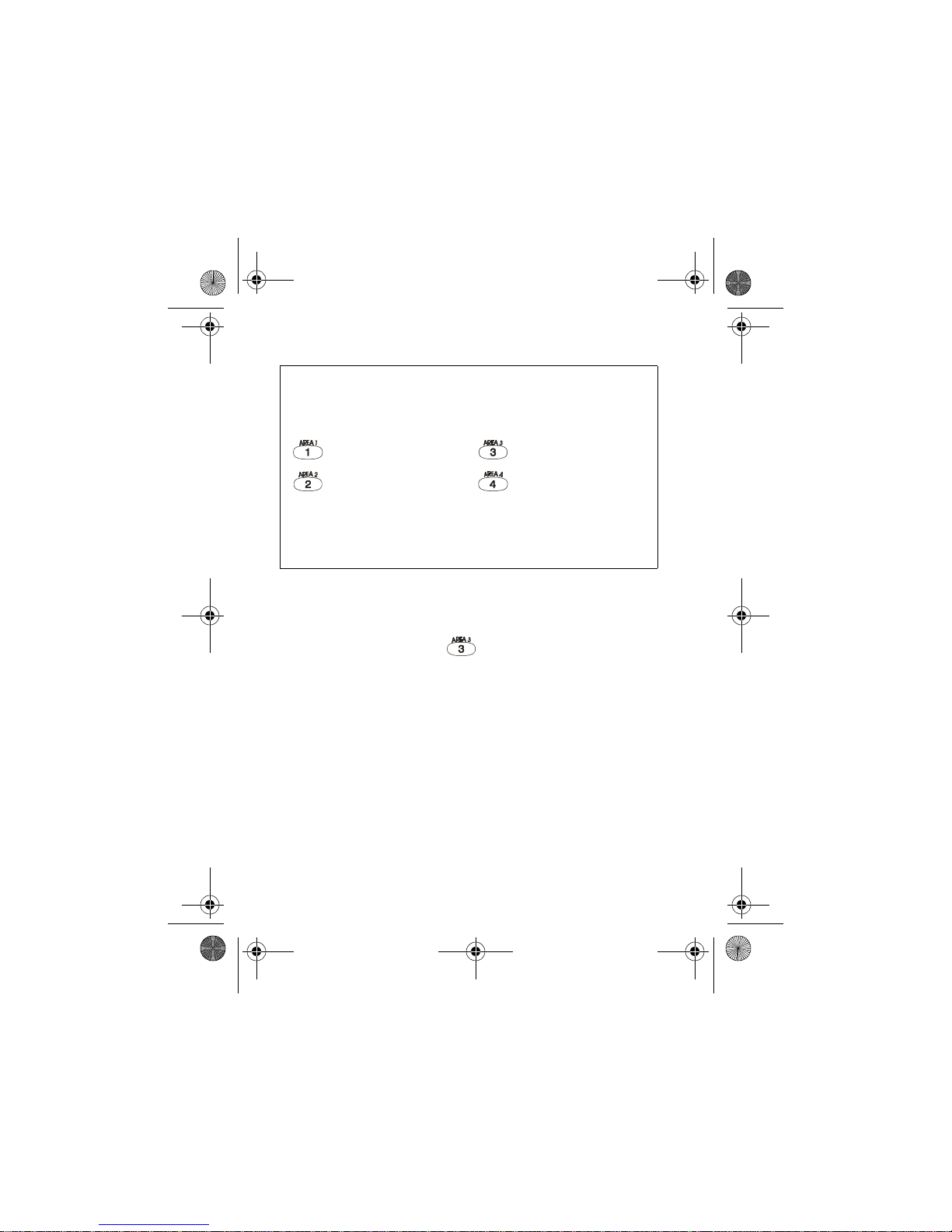
How do I see the status of the zones?
1) Enter your [ACCESS CODE]
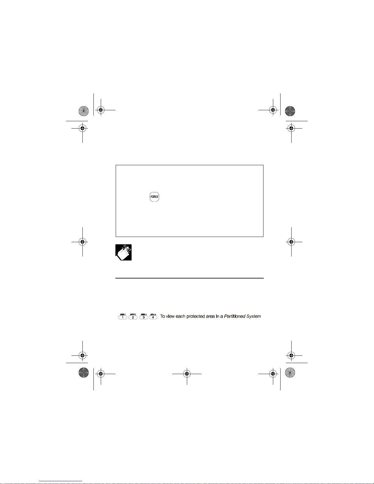
2) Press the numbered button corresponding to the desired area:
= Area 1 = Area 3
= Area 2 = Area 4
3) The keypad will emit a Confirmation Beep and will remain in that
Area’s status for two minutes then return to Normal or
Confidential Mode. You can perform the next desired action
from Area Status Display.
In Area Status Display the following will illuminate for the area
selected:
• The Area Symbol (A1, A2, A3, and A4) if the area is armed.
For example, if you press , and Area 3 is armed, [A3] will
illuminate.
• The Numerical Symbols representing any open zones. For
example, if zone 6 was open, then the Numerical Symbol [6]
would illuminate.
• The [MEM] Symbol if any alarms have occurred
• The [TRBL] Symbol if any troubles are occurring
• The [STAY] Symbol if the area is Stay or Instant Armed
• The [FORCE] Symbol if the area is Force Armed
• The [BYP] Symbol if zones are bypassed
• The state of the “Status” Light
LED Keypads 9
Page 12
KLEDEU03.fm Page 10 Friday, May 4, 2001 11:25 AM
3.0 ARMING
When the system is armed, it will respond to any breach in the
zones according to the way each zone is programmed. For
example, if someone opens a window that is armed, the system
can trigger an alarm and alert your Security Company.
3.1 EXIT DELAY TIMER
When you arm the system, it will start the Exit Delay Timer to
provide you with enough time to exit the protected area before the
system is armed. The Status Light will flash green while the time
elapses. The timer can be assigned different time limits and the
keypad can be programmed to beep while the time elapses on the
timer. Discuss these options with your installer.
3.2 REGULAR ARMING
This method is used for the everyday arming of the system. All
zones within the protected area must be closed to arm the
system. To check the status of the zones in each area, refer to
section 2.5 on page 8 Area Status Display.
10 User’s Manual
Page 13
KLEDEU03.fm Page 11 Friday, May 4, 2001 11:25 AM
How do I regular arm the system?
1) Enter your [ACCESS CODE].
The keypad will emit a Confirmation Beep. The [ACCESS]
Symbol will flash.
2) Press the button.
If you have access to more than one area, press the
Number Button representing the area you want to arm or
[0] for all assigned areas.
After the Confirmation Beep, the Exit Delay Timer will begin.
If enabled by your installer, the One-Touch Buttons
(section 3.6 on page 14) or a keyswitch (section 3.7 on
page 15) can also be used to arm the area.
3.3 STAY ARMING
Stay Arming will partially arm your system to permit you to
remain in the protected area. Based on your instructions, your
installer will program specific zones as Stay Zones. These zones
will not arm when you Stay Arm. For example, you can arm your
doors and windows at home without arming the motion detectors
so you will be protected while you sleep. Only User Access
Codes with the Stay and Instant Arm option enabled can Stay
Arm the system. Also, see section 3.8 on page 16 Auto-Arming
for another everyday arming option.
LED Keypads 11
Page 14

KLEDEU03.fm Page 12 Friday, May 4, 2001 11:25 AM
How do I Stay Arm?
1) Enter your [ACCESS CODE].
The keypad will emit a Confirmation Beep. The [ACCESS]
Symbol will flash.
2) Press button.
If you have access to more than one area, press the
Number Button representing the area you want to Stay
Arm or [0] for all assigned areas.
After the Confirmation Beep, the Exit Delay Timer will
begin the countdown to arming.
If enabled by your installer, the One-Touch Buttons
(section 3.6 on page 14) or a keyswitch (section 3.7 on
page 15) can also be used to arm the area.
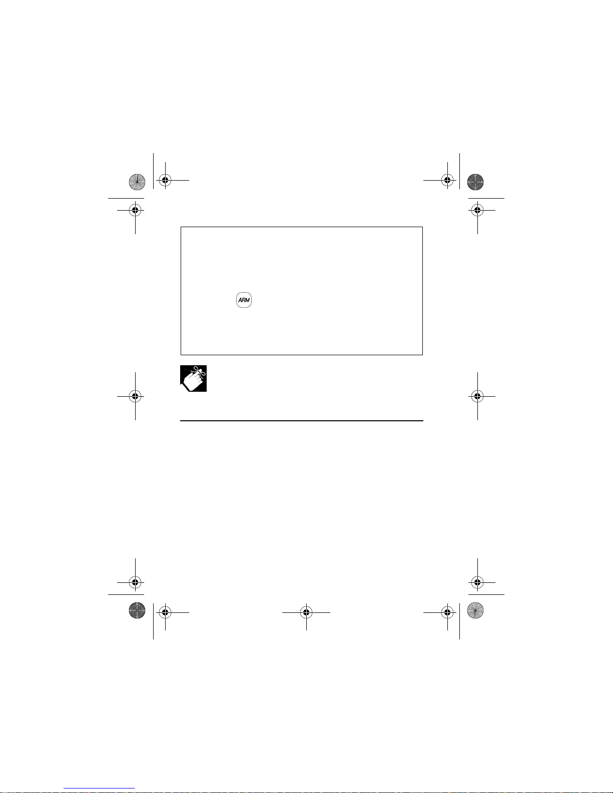
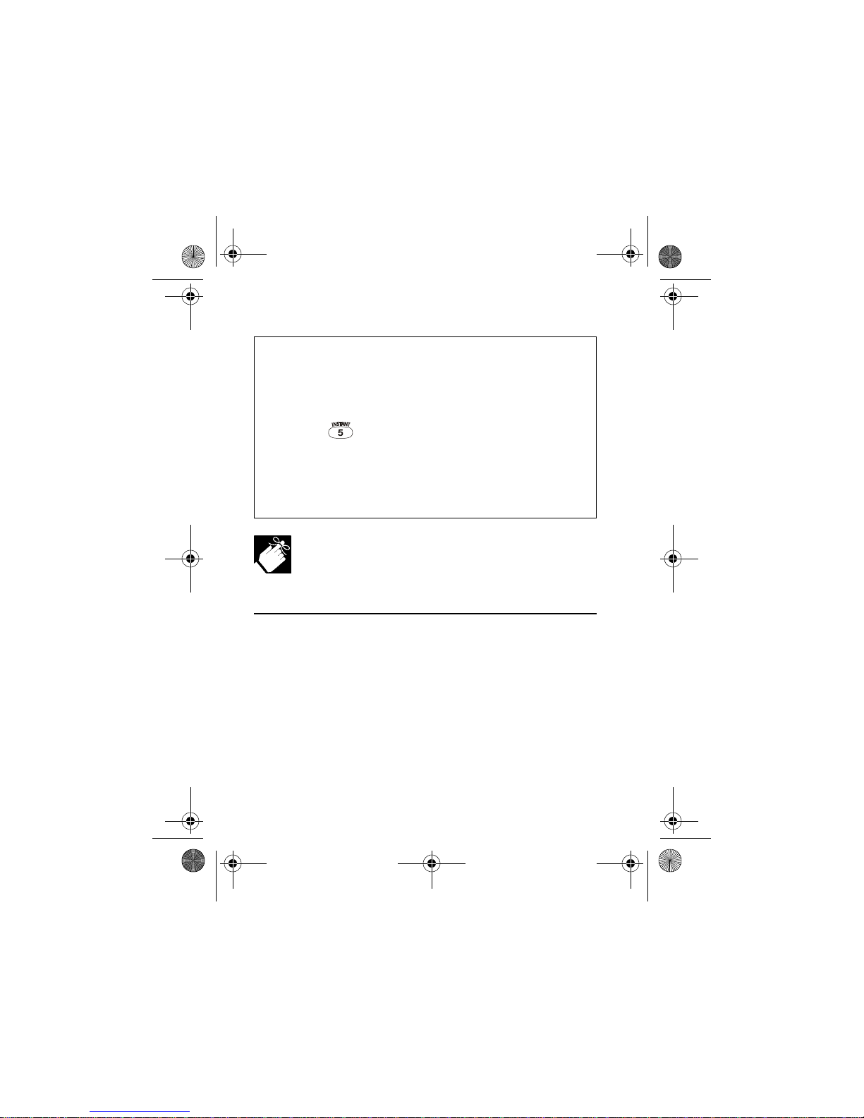
3.4 INSTANT ARMING
This feature is similar to Stay Arming. Instant Arming will partially arm
your system to permit you to remain in the protected area, but all
zones, including the entry/exit point, are changed to instant alarm
zones. Therefore, if any armed zone is breached, the alarm will
instantly be triggered. Only User Access Codes with the Stay and
Instant Arm option enabled will be able to Instant Arm.
12 User’s Manual
Page 15
KLEDEU03.fm Page 13 Friday, May 4, 2001 11:25 AM
How do I Instant Arm?
1) Enter your [ACCESS CODE].
The keypad will emit a Confirmation Beep. The [ACCESS]
Symbol will flash.
2) Press the button.
If you have access to more than one area, press the Number
Button representing the area you want to Instant Arm or [0]
for all assigned areas.
After the Confirmation Beep, the Exit Delay Timer will begin
the countdown to arming.
If enabled by your installer, the One-Touch Buttons
(section 3.6 on page 14) or a keyswitch (section 3.7 on
page 15) can also be used to arm the area.
3.5 FORCE ARMING
Force Arming allows you to arm your system when specific
zones are open. Certain zones can be programmed by the
installer to remain unarmed when you initiate Force Arming.
Once the open zone is closed, however, the system will then arm
it as well. Only User Access Codes with the Force Arm option
enabled can Force Arm the system. Also, see section 3.8 on
page 16 Auto-Arming for another everyday arming option.
This feature is commonly used when a motion detector is
protecting an area that is occupied by a keypad. During Force
LED Keypads 13
Page 16
KLEDEU03.fm Page 14 Friday, May 4, 2001 11:25 AM
arming, the motion detector will remain unarmed until you exit
the area that it protects. The system will then arm the motion
detector.
How do I Force Arm?
1) Enter your [ACCESS CODE].
2) Press the button.
If you have access to more than one area, press the
Number Button representing the area you want to Force
Arm or [0] for all assigned areas.
After the Confirmation Beep, the Exit Delay Timer will
begin the countdown to arming.
I
f enabled by your installer, the One-Touch Buttons
(section 3.6 on page 14) or a keyswitch (section 3.7 on
page 15) can also be used to arm the area.
3.6 ONE-TOUCH BUTTONS
At the touch of a button you can view the Area Status Display
(see section 2.5) for a Partitioned System (see section 2.4).
Press and hold:
Your installer can also program your system to respond to
14 User’s Manual
Page 17
KLEDEU03.fm Page 15 Friday, May 4, 2001 11:25 AM
certain features with just a touch of a button. You will then have
access to the following features without using your User Access
Code by pressing and holding the desired button.
Press and hold:
For more information concerning these features, please refer to
their respective sections.
3.7 KEYSWITCH ARMING
Your installer can add a keyswitch to arm and disarm your
system. The keyswitch can be programmed to Regular, Stay,
Force, or Instant Arm, and Disarm a specific area. The keyswitch
will also be programmed by the installer to function as a
Maintained or Momentary keyswitch.
3.7.1 Maintained Keyswitch
To arm the system, place in the “on” position.
To disarm the system, place in the “off” position.
3.7.2 Momentary keyswitch
To arm the system, place in the “on” position briefly then place it
LED Keypads 15
Page 18

KLEDEU03.fm Page 16 Friday, May 4, 2001 11:25 AM
back in the “off” position. Repeating this process will disarm the
system.
3.8 AUTO-ARMING
You can program area(s) to arm automatically (if enabled by your
installer).
3.8.1 Timed Auto-Arming
If enabled, you can set the time that an area will arm itself
automatically.
How do I set the Auto-Arming timer?
1) Enter your [ACCESS CODE].
The keypad will emit a Confirmation Beep. The [ACCESS]
Symbol will flash.
2) Press the button.
The keypad will emit a Confirmation Beep. The [PRG] Symbol and Area Symbol(s) will flash.
3) Press the button.
The
[
PRG
]
Symbol will flash and the
[
MEM
]
Symbol will illuminate.
If you have access to more than one area, the Area Symbols that you have access to will illuminate in sequence.
Press the Number Button representing the area you want
to arm.
16 User’s Manual
Page 19

KLEDEU03.fm Page 17 Friday, May 4, 2001 11:25 AM
4) Enter the [TIME] you want the area to be armed according to
the 24-hour clock (i.e. 9 a.m. is 09:00 and 9 p.m. is 21:00).
The [MEM] Symbol will flash if a time is not already programmed. The [PRG] Symbol, the Area Symbol of the chosen area, and the first number of the previous time set will
illuminate ([10] Symbol = zero).
5) Press the button to save and exit.
To view the time set, instead of entering the [TIME] in Step 4, the
first number of the time you set will illuminate. Press the
button to illuminate the numbers one at a time (the Numerical
Symbol [10] represents zero).
3.8.2 No Movement Auto-Arming
Your system can be programmed to send a report to the Security
Company and/or arm the system if there is no activity in the area
during a specified period of time. Speak to your installer about
this feature.
3.9 BYPASS PROGRAMMING
The installer can program certain zones with the bypass option.
This will enable you to program the system to bypass certain
zones when you arm the protected area. When a zone is
bypassed, it will remain unarmed once the system is armed. This
option may be useful, for example, when you are renovating part
of the protected area. The system will keep the bypassed
zone(s) in memory until the area is armed. Once the area is
LED Keypads 17
Page 20

KLEDEU03.fm Page 18 Friday, May 4, 2001 11:25 AM
disarmed, the system will unbypass the zones.
To bypass a zone:
The zone must have the Bypass option programmed by the installer.
Your User Access Code must be programmed to enable the Bypass option.
Your User Access Code must have access to the zone’s Area Assignment.
Fire Zones cannot be bypassed.
How do I activate the Zone Bypass feature for a zone?
1) Enter your [ACCESS CODE].
The keypad will emit a Confirmation Beep. The [ACCESS]
Symbol will flash.
2) Press the button.
The [PRG] Symbol will illuminate and the [BYP] Symbol will
flash.
3) Enter the two-digit number(s) of the zone(s) you want to
Bypass and the corresponding number(s) will illuminate. If
a zone’s number is illuminated and you re-enter its number,
the zone will unbypass and the number will extinguish.
If a zone’s number does not illuminate and the keypad
emits a Rejection Beep, the zone may not have the
Bypass feature accessible.
18 User’s Manual
Page 21

KLEDEU03.fm Page 19 Friday, May 4, 2001 11:25 AM
4) Press the button to exit.
The [BYP] Symbol will remain illuminated.
3.9.1 Bypass Recall
Bypass Recall reinstates all the zones that had Zone Bypass
activated the last time the system was armed.
If you have a Partitioned System, only the zones in the
area(s) assigned to your User Access Code will be
affected.
How do I activate Bypass Recall?
1) Enter your [ACCESS CODE].
The keypad will emit a Confirmation Beep. The [ACCESS]
Symbol will flash.
2) Press the button.
The keypad will emit a Confirmation Beep. The [PRG] Symbol will illuminate and the [BYP] Symbol will flash.
3) Press the button.
All zones bypassed during the last time the system was
armed will illuminate and will be bypassed.
4) If you wish, re-enter the zone’s number to change a bypassed
zone to an unbypassed zone and vice versa.
LED Keypads 19
Page 22

KLEDEU03.fm Page 20 Friday, May 4, 2001 11:25 AM
5) Press the button to exit.
4.0 DISARMING
When the system is disarmed, the control panel deactivates the
zones so the alarm will not be triggered if zones are breached.
Any user can disarm the system unless their code has been
assigned the Arm Only option.
4.1 ENTRY DELAY TIMER
Based on your instructions the installer will program designated
entry points, such as the front door or the garage door, with an
entry delay. This delay will allow you enough time to enter your
code to disarm the system before the alarm is triggered.
4.2 DISARMING AN ARMED SYSTEM
You will only be able to disarm the area to which your User
Access Code is assigned. User Access Codes with the Arm Only
option will not be able to disarm the system.
20 User’s Manual
Page 23

KLEDEU03.fm Page 21 Friday, May 4, 2001 11:25 AM
How do I disarm the system?
If you are disarming a Stay or Instant Armed area, use Step 2 and Step 3.
For areas armed with the other arming features, use Step 1 and Step 2.
1) Enter through a designated entry.
The keypad will beep to acknowledge the entry, the Status Light
will turn red, and the Entry Delay Timer will begin the countdown.
2) Enter your [ACCESS CODE].
3) Press the button.
If you have access to more than one area, press the
Number Button representing the area you want to disarm
or [0] for all assigned areas.
The keypad will emit a Confirmation Beep.
If enabled by your installer, the One-Touch Buttons
(section 3.6 on page 14) or a keyswitch (section 3.7 on
page 15) can also be used to disarm the area.
How do I disarm the system if the alarm was accidentally
triggered?
1) Enter your [ACCESS CODE].
2) Call your Security Company quickly to advise them of the
false alarm.
LED Keypads 21
Page 24

KLEDEU03.fm Page 22 Friday, May 4, 2001 11:25 AM
4.3 ALARM MEMORY DISPLAY
Your system will record all the alarms that occurred during the
last armed period. If an alarm was triggered in any area assigned
to the keypad, the [MEM] Symbol will illuminate.
In case of a burglar alarm, leave the premises and
call your Security Company from a safe place.
How do I view the list of the alarms that occurred?
When the [MEM] Symbol is illuminated:
1) Press the button.
The [MEM] Symbol will flash and the Numerical Symbols for
each zone whose alarm was triggered will illuminate.
2) Press the button to exit the Alarm Memory Display.
The [MEM] Symbol and Numerical Symbols will extinguish.
The zones that were in alarm will remain in the Alarm
Memory until the next time that area is armed.
5.0 ACCESS CODES
Access Codes are codes that will allow you and others to access
the system. These codes can be programmed to permit access
to all or some features and areas. The installer will program User
22 User’s Manual
Page 25

KLEDEU03.fm Page 23 Friday, May 4, 2001 11:25 AM
Access Codes to be four digits, six digits, or variable from one to
six digits in length. Each digit can be any value between zero and
nine. If the installer programmed your system to accept a
variable code length, you may have to press the button
after entering their User Access Code. Only the System Master
Code cannot be less than 4 digits.
5.1 SYSTEM MASTER CODE (default 123456)
The System Master Code will give you access to all the features
as well as the ability to add, modify, or delete any User Access
Codes. We suggest that you change this code to prevent others
from accessing and changing your options without authorization.
How do I change the System Master Code?
1) Enter the current [SYSTEM MASTER CODE].
The keypad will emit a Confirmation Beep. The [ACCESS]
Symbol will flash.
2) Press the button.
The keypad will emit a Confirmation Beep. The Area Symbols and the [PRG] Symbol will flash.
3) Press the button.
The keypad will emit a Confirmation Beep. The Area Symbol(s) and the [ACCESS] Symbol will illuminate. The [PRG]
Symbol will flash.
LED Keypads 23
Page 26

KLEDEU03.fm Page 24 Friday, May 4, 2001 11:25 AM
4) Enter the numbers [0] and [1].
The keypad will emit a Confirmation Beep. The [PRG] Symbol and the Numerical Symbol of the first number in the
code will illuminate ([10] = zero). The Area Symbols and
[ACCESS] Symbol will extinguish.
5) Enter a [NEW CODE].
The Numerical Symbols for the next numbers in the code
will illuminate one at a time as you enter the new code.
When you have entered the maximum number of digits, the
keypad will emit a Confirmation Beep.
6) Press the button to exit.
5.2 USER ACCESS CODES
Your system can support up to 95 User Access Codes. All codes
are given a User Number between 02 and 96 (Code 01 is the
System Master Code).
User Access Codes can be programmed with various options
that will allow you to control the access to your system. Only the
System Master Code and codes with the Master feature can
program User Access Codes with their User Options and Area
Assignment.
24 User’s Manual
Page 27

KLEDEU03.fm Page 25 Friday, May 4, 2001 11:25 AM
How do I program a User Access Code?
1) Enter your [ACCESS CODE]
System Master Code or User Access Code with the Master
feature only.
2) Press to enter the User Programming Menu.
The Area Symbols of the areas assigned to your User Access
Code and the [PRG] Symbol will flash.
3) Press the button.
The Area Symbols of the areas assigned to your User Access
Code and the [ACCESS] Symbol will illuminate. The [PRG] Sym-
bol will continue to flash.
4) Enter the 2-digit User Number (02 to 96) you want to program.
The [ACCESS] Symbol will flash for an unused code. If the code is
used, [PRG] Symbol and first number of the code will illuminate.
The [ACCESS] Symbol and the Area Symbols will extinguish.
5) Enter a User Code. If you do not want to change an existing
one, press until you reach User Options.
The keypad will emit a Half Beep when it switches to User
Options. Pre-existing options will illuminate.
6) Program the User Options (see section 5.3 on page 26) by
turning ON or OFF the options. Once the options are
programmed, press to reach the Area Assignment.
The keypad will emit a Half Beep when it switches to Area
Assignment. Pre-existing assignments will illuminate.
LED Keypads 25
Page 28

KLEDEU03.fm Page 26 Friday, May 4, 2001 11:25 AM
7) Program the Area Assignment (see Table 2). Press to
return to User Options or press to save and exit.
The keypad will emit a Confirmation Beep to confirm the code’s
acceptance.
If the keypad emits a Rejection Beep, you may have chosen an
existing User Code or the Master Code used to modify or create
the code does not have access to the User Options or Area
Assignment programmed.
To view the code programmed, instead of entering the User
Code in Step 5, the first number of the code programmed will
illuminate. Press the button and the numbers will illuminate
one at a time as you press the button (the Numerical Symbol [10]
represents zero).
5.3 USER OPTIONS
Options on the User Access Codes that activate access to
features.
The User Code Option or Area is considered ON when
the corresponding Numerical Symbol is illuminated.
You turn the Numerical Symbols ON and OFF by
pressing the Numerical Buttons on the keypad.
Option [1] and [2]: Master Feature
When option [1] is OFF, the Master Feature is disabled.
When option [1] is ON and option [2] is OFF, the user can only
26 User’s Manual
Page 29

KLEDEU03.fm Page 27 Friday, May 4, 2001 11:25 AM
modify user access codes.
When both options [1] and [2] are ON, the user has Full Master
rights. The user can create or modify other user access codes,
user options and Area assignment according to its own User
Options and Area Assignment.
Option [3]: Duress Feature
When option [3] is ON, the Duress feature is enabled. The User
can arm, disarm, and send a silent alarm to the Security Alarm
Company. This feature is used when someone forces you to arm
or disarm areas.
Option [4]: Bypass Feature
When option [4] is ON, the Bypass feature is enabled. This
feature allows you to deactivate zones.
Option [5]: Arm Only Feature
When option [5] is ON, the Arm Only feature is enabled. The
user can only arm assigned areas, but CANNOT disarm.
Option [6]: Stay & Instant Arm Feature
When option [6] is ON, the Stay and Instant Arm features are
enabled. The user can now Stay or Instant Arm their assigned
areas.
Option [7]: Force Arm Feature
When option [7] is ON, the Force arm feature is enabled. The
user can now Force arm their assigned areas.
Option [8]: Area Access Feature
When option [8] is ON, the keypad will permit access to all the
LED Keypads 27
Page 30

KLEDEU03.fm Page 28 Friday, May 4, 2001 11:25 AM
areas assigned to the user access code regardless of which
areas the keypad controls. When option [8] is OFF, the keypad
will only permit access to the areas it controls.
5.4 AREA ASSIGNMENT
In a Partitioned System the system can be divided into four
distinct protected areas. Programming access to a specific area
or areas is called Area Assignment. User Access Codes are only
able to perform actions (arming, disarming, etc.) in the area(s)
the code is assigned.
Press button on/
off
Area Assignment
on
on
on
on
Access to Area 1
Access to Area 2
Access to Area 3
Access to Area 4
All four buttons off Controls PGMs only (if PGMs are
programmed by the installer).
28 User’s Manual
Page 31

KLEDEU03.fm Page 29 Friday, May 4, 2001 11:25 AM
When the area's number is OFF, the User does not have
access to that protected area.
5.5 ERASING ACCESS CODES
To delete existing Access Codes, press the button in steps
5, 6, and 7 in “How do I program Access Codes” starting on
page25. Once the information is erased, press the button
to save and exit.
6.0 TROUBLE DISPLAY
When your system experiences problems or is tampered with,
the [TRBL] Symbol will illuminate. Most of the trouble conditions
will be programmed by your installer to be reported directly to
your Security Company (if connected). The keypad will only
display troubles that occur in the area(s) to which the keypad has
been assigned.
Potential troubles have been sorted into eight groups. The Group
headings are listed below with a brief explanation of the potential
troubles sorted within each group.
We strongly suggest that you simply inform your
Security Company of the trouble and allow them to
service your system.
LED Keypads 29
Page 32

KLEDEU03.fm Page 30 Friday, May 4, 2001 11:25 AM
How do I view the Trouble Display?
1) The [TRBL] Symbol illuminates.
2) Press the button.
The [TRBL] Symbol will flash and the Numerical Symbol(s)
representing Group heading number(s) will illuminate.
3) Press the Numerical Symbol corresponding to the Group
heading to view the specific trouble.
If your keypad is in Confidential Mode (see section 2.3.2) ,
the [TRBL] Symbol will not illuminate until you enter your
User Access Code or press a button depending on how
the keypad was programmed.
6.0.1 Group [1]: System
Trouble [1]: AC Failure
The control panel has detected a power failure. This means that
your system is running on the back-up battery. The AC Light on
your keypad will be turned off during a power failure. If this
Trouble occurs when your establishment is not experiencing a
power failure, call your Security Company for repairs.
Trouble [2]: Battery Trouble
This means the back-up battery is disconnected, needs to be
recharged, or replaced.
30 User’s Manual
Page 33

KLEDEU03.fm Page 31 Friday, May 4, 2001 11:25 AM
Trouble [5]: Bell Absent
The control panel has detected that the bell or siren is not
connected.
6.0.2 Group [5]: Zone Tamper
The Numerical Symbols for the zone or zones that have been
tampered with will be illuminated.
6.0.3 Group [6]: Zone Low Battery
If a wireless device's battery needs to be replaced, the Numerical
Symbol for the zone that it is assigned to will be illuminated. Also,
the yellow light on the device will flash to indicate this trouble.
6.0.4 Group [7]: Zone Fault
A smoke detector is experiencing a wiring problem, needs to be
cleaned, or a wireless device is no longer communicating with its
receiver.
6.0.5 Group [8]: Clock Loss
The time and date have been reset to the default. This is the only
Trouble that we recommend that you correct.
7.0 ADDITIONAL FEATURES
7.1 PROGRAMMABLE OUTPUTS (PGMS)
Your system includes two or more programmable outputs
(PGMs) that can be programmed by your installer. A PGM
triggers when a predetermined event or series of events occurs
LED Keypads 31
Page 34

KLEDEU03.fm Page 32 Friday, May 4, 2001 11:25 AM
in your system. The PGMs can be programmed to reset smoke
alarms, turn on light switches, open or close garage doors and
much more. Ask your installer about this useful feature.
7.2 SET TIME AND DATE
How do I reset the time and date?
When the
1) Press the button.
2) Enter the hour and minutes according to a 24-hour clock
3) Enter the correct date according to yyyy/mm/dd.
[
TRBL
]
Symbol flashes and the
[8]
Symbol is illuminated.
The [TRBL] Symbol will flash, the [PRG] Symbol and a
Numerical Symbol are illuminated.
(i.e. 9 a.m. is 09:00 and 9 p.m. is 21:00).
The default time will be illuminated one number at a time
as you enter the correct time. The keypad will emit a Half
Beep when it accepts the new time and switches to programming the date.
The default date will be illuminated one number at a time
as you enter the correct date. The keypad will emit a Confirmation Beep when it accepts the new date.
32 User’s Manual
Page 35

KLEDEU03.fm Page 33 Friday, May 4, 2001 11:25 AM
4) Press the button to exit the menu.
If there are other Troubles with the system, the [TRBL]
Symbol will remain illuminated until they are resolved. Contact your Security Company to effect repairs.
7.3 PANIC ALARMS
Your system can be programmed to send an alarm to your
Security Company to alert them that you require emergency
assistance when you press a pre-determined combination of
Number Buttons on the keypad. The three Panic Alarms can be
programmed to request help from the police, a medical facility,
the fire department, or anyone you wish. Ask your installer about
programming these features in your system.
Emergency Panic
When you press the and buttons at the same time
and hold them for two seconds, the system will generate an
alarm. The alarm can be programmed to be either silent or
audible according to your preference.
Auxiliary Panic
When you press the and buttons at the same time
and hold them for two seconds, the system will generate an
alarm. The alarm can be programmed to be either a silent or
audible according to your preference.
LED Keypads 33
Page 36

KLEDEU03.fm Page 34 Friday, May 4, 2001 11:25 AM
Fire Panic
When you press the and buttons at the same time
and hold them for two seconds, the system will generate an
alarm. The alarm can be programmed to be either a silent or
audible according to your preference.
7.4 PROGRAMMING CHIME ZONES
You can program the keypads to emit a rapid, intermittent beep
whenever designated zones are opened or only when opened
between certain hours. These zones are referred to as Chime
Zones. Each keypad must be Chime programmed separately.
Your installer can program your Chimed zones to also beep upon
closure.
7.4.1 Activating a Chime Zone
How do I program a keypad to beep every time a zone opens?
1) Enter your [ACCESS CODE].
The keypad will emit a Confirmation Beep. The [ACCESS]
Symbol will flash.
2) Press the button to enter the Chiming Menu.
The keypad will emit a Confirmation Beep. The [PRG] Sym-
bol and Area Symbol(s) will flash.
34 User’s Manual
Page 37

KLEDEU03.fm Page 35 Friday, May 4, 2001 11:25 AM
3) Press the button.
The keypad will emit a Confirmation Beep. The [PRG] Sym-
bol and any already Chimed zones will illuminate.
4) Enter the two-digit zone number(s) you want to designate
as Chimed.
The keypad will emit a Confirmation Beep and the Numeri-
cal Symbol(s) corresponding to the zone(s) will illuminate.
If you re-enter the number of an illuminated Numerical
Symbol, the corresponding zone will unchime and the
Numerical Symbol will extinguish.
5) Press the button to exit.
7.4.2 Setting a Chime Zone time period
How do I program all the keypad’s Chimed zones to beep
only when they open between specific hours?
1) Enter your [ACCESS CODE].
The keypad will emit a Confirmation Beep. The [ACCESS]
Symbol will flash.
2) Press the button to enter the Chiming Menu.
The keypad will emit a Confirmation Beep. The [PRG] Sym-
bol and Area Symbol(s) will flash.
LED Keypads 35
Page 38

KLEDEU03.fm Page 36 Friday, May 4, 2001 11:25 AM
3) Press the button.
The keypad will emit a Confirmation Beep. The [PRG] Sym-
bol and a Numerical Symbol will illuminate. The Numerical
Symbol represents the first number of the previously set
time ([10] Symbol = zero). When the [A2] and [A3] Symbols
flash, no time is set.
4) Enter the time you want all Chimed zones to start beeping
when they open according to the 24-hour clock (i.e. 9 a.m.
is 09:00 and 9 p.m. is 21:00).
The keypad will emit a Half Beep.
5) Enter the time you want all Chimed zones to stop beeping
when they open according to the 24-hour clock. If you want
the Chimed zones to beep every time they open, enter the
same time set in Step 4.
The keypad will emit a Confirmation Beep.
6) Press the button to exit.
7.5 QUICK FUNCTION BUTTONS
You will only need to use the Quick Function Buttons upon your
installer or Security Company's request. Only the System Master
Code or User Access Codes with the Master feature enabled will
be able to access these functions.
36 User’s Manual
Page 39

KLEDEU03.fm Page 37 Friday, May 4, 2001 11:25 AM
How do I access the Quick Function Buttons?
1)
Enter your
[
SYSTEM MASTER CODE
] or [
ACCESS CODE
]
with Master
feature
2) Press the button.
3) Press one of the following for the system to:
button: send a test report to the Security Company
button: call the Security Company's diagnostic software.
button: answer the Security Company's diagnostic software.
button:
cancel
the communication with the Security Company.
8.0 FIRE AND BURGLAR ALARMS
8.1 STANDARD FIRE ZONE
During a fire alarm, the bell/siren will emit an intermittent sound
(BEEP-BEEP-BEEP) until silenced or reset. If the zone is a Standard
Fire Zone, the system can immediately send an alert to your
Security Company.
LED Keypads 37
Page 40

KLEDEU03.fm Page 38 Friday, May 4, 2001 11:25 AM
How do I disarm the system if it was accidentally
triggered?
1) Enter your [ACCESS CODE].
2) Call your Security Company quickly to advise them of the false
alarm.
The Fire Zone may reset itself once the problem has
cleared. If it does not, simultaneously press and
hold the and buttons for two seconds or
speak to your installer.
8.2 DELAYED FIRE ZONE
During a fire alarm, the bell/siren will emit an intermittent sound
(BEEP-BEEP-BEEP) until silenced or reset. If the zone is a Delayed
Fire Zone, there is an automatic delay before the system
contacts the Security Company (see Figure 8-1). This will
prevent unnecessary reporting of false alarms.
If you are unable to cancel the fire alarm, the system
will send an alert (if connected). Call your Security
Company to advise them of the false alarm.
38 User’s Manual
Page 41

KLEDEU03.fm Page 39 Friday, May 4, 2001 11:25 AM
Figure 8-1: Delayed Fire Zone
LED Keypads 39
Page 42

KLEDEU03.fm Page 40 Friday, May 4, 2001 11:25 AM
What do I do if the fire alarm is set off accidentally?
1) Press the button within 30 seconds of the alarm.
2) Clear the problem from the area.
3) If problem remains, the alarm will sound again. Press
again. These steps will instruct the system to delay reporting
the alert to the Security Company.
The Fire Zone may reset itself once the smoke has
cleared. If it does not, simultaneously press and
hold the and buttons for two seconds or
speak to your installer.
8.3 FIRE SAFETY TIPS
During a fire, time is the biggest enemy and every second
counts! What should you do to prepare in case of a fire in your
home or business?
1. Remind everyone to escape first, then call for help.
2. Develop a fire escape plan and designate a meeting place
outside.
3. Practice the escape plan frequently.
4. Plan two ways to escape from every room, if possible.
5. Practice feeling the way out with eyes closed.
6. Remind everyone never to stand up during a fire, always
crawl low under the smoke and keep mouths covered.
7. Instruct everyone never to return to a burning building for any
40 User’s Manual
Page 43

KLEDEU03.fm Page 41 Friday, May 4, 2001 11:25 AM
reason; it may cost them their life.
8. Check smoke alarms regularly; working smoke alarms
dramatically increase everyone's chances of surviving a fire.
8.4 MINIMIZING HOME FIRE HAZARDS
How can you avoid the three most common causes of fires at
home?
1. Never leave cooking food unattended. Cooking fires often
result from unattended cooking and human error, rather than
mechanical failure.
2. Stay alert when smoking. Careless smoking is the leading
cause of fire deaths. Smoke detectors and smolder-resistant
bedding and upholstered furniture are significant fire
deterrents.
3. Maintain your heating system. Heating is the second leading
cause of residential fires. However, heating fires are a larger
problem in single family homes than in apartments. Unlike
apartments, the heating systems in single family homes are
often not professionally maintained.
4. Since fires produce smoke and deadly gases that can
overcome occupants while they sleep, smoke detectors
should be installed outside each separate sleeping area in
the immediate vicinity of the bedrooms and on each
additional story of the family living unit, including basements.
8.5 BURGLAR ALARM
If your armed system is breached, the burglar alarm devices
specific to your system will be triggered. If your keypad is in
LED Keypads 41
Page 44

KLEDEU03.fm Page 42 Friday, May 4, 2001 11:25 AM
Normal Mode:
• The Status Light and Area Symbol of the area in alarm may
flash red
• The keypad may beep
• The [MEM] Symbol will illuminate
• The bell or siren may be activated
• The zones in alarm will be recorded in the Alarm Memory
Display.
In case of a burglar alarm, leave the premises and
call your Security Company from a safe place.
9.0 TESTING AND MAINTENANCE
9.1 BURGLAR ALARM TESTING
Two people are needed to complete this test. One person will
watch the keypad while the other person walks around and
opens the zones (i.e. open the doors and windows that are
protected, walk in the path of the motion detectors, etc.). The
Numerical Symbols for the opened zones will illuminate when
opened. If a zone does not register, contact your installer. Use
Area Status Display to view the open zones in other areas
assigned to the keypad. Your installer will provide details on the
best way to test your particular system.
42 User’s Manual
Page 45

KLEDEU03.fm Page 43 Friday, May 4, 2001 11:25 AM
9.2 FIRE ALARM TESTING
Do NOT use an open flame or burning materials to test your fire
detection devices. Your installer will provide details on the best
way to test your particular system.
9.3 SYSTEM MAINTENANCE
Under normal use your system requires virtually no maintenance
other than regular testing. It is recommended that your installer
change the battery every three years.
9.4 SYSTEM TEST
Speak to your installer before conducting a system test since the
system must be programmed to respond to the test instructions.
It is normally recommended that you conduct the system test
once a week, but contact your installer for instructions
concerning your particular system.
How do I conduct the system test?
1) Call Security Company to advise them that you are testing
the system.
2) Enter your [ACCESS CODE].
LED Keypads 43
Page 46

KLEDEU03.fm Page 44 Friday, May 4, 2001 11:25 AM
3) Press the button.
The system will test all its connections and can send a report
to your Security Company. If the system detects a problem,
the [TRBL] Symbol will illuminate (see section 6.0). Call your
installer for repairs.
10.0 SYSTEM CHECKLIST
Important: Keep this information in a secure location.
10.1 ZONE DESCRIPTION
Is this a Partitioned System? Yes l No l
Area 1 = ____________________________________________
Area 2 = ____________________________________________
Area 3 = ____________________________________________
Area 4 = ____________________________________________
44 User’s Manual
Page 47

KLEDEU03.fm Page 45 Friday, May 4, 2001 11:25 AM
Zone # and
Description
01:
02:
03:
04:
05:
06:
07:
08:
09:
10:
11:
12:
13:
14:
15:
16:
17:
Area
1 2 3 4
l l l l
l l l l
l l l l
l l l l
l l l l
l l l l
l l l l
l l l l
l l l l
l l l l
l l l l
l l l l
l l l l
l l l l
l l l l
l l l l
l l l l
Zone # and
Description
18:
19:
20:
21:
22:
23:
24:
25:
26:
27:
28:
29:
30:
31:
32:
33:
34:
Area
1 2 3 4
l l l l
l l l l
l l l l
l l l l
l l l l
l l l l
l l l l
l l l l
l l l l
l l l l
l l l l
l l l l
l l l l
l l l l
l l l l
l l l l
l l l l
LED Keypads 45
Page 48

KLEDEU03.fm Page 46 Friday, May 4, 2001 11:25 AM
Zone # and
Description
35:
36:
37:
38:
39:
40:
41:
Entry Delay: Exit Delay:
Area 1 is _____ seconds Area 1 is _____ seconds
Area 2 is _____ seconds Area 2 is _____ seconds
Area 3 is _____ seconds Area 3 is _____ seconds
Area 4 is _____ seconds Area 4 is _____ seconds
Area
1 2 3 4
l l l l
l l l l
l l l l
l l l l
l l l l
l l l l
l l l l
Zone # and
Description
42:
43:
44:
45:
46:
47:
48:
1 2 3 4
l l l l
l l l l
l l l l
l l l l
l l l l
l l l l
l l l l
10.2 SPECIAL BUTTONS AND FEATURES
One-Touch Buttons:
Place a [if the One-Touch Button is activated.
Area
46 User’s Manual
Page 49

KLEDEU03.fm Page 47 Friday, May 4, 2001 11:25 AM
l Stay Arming l Bypass Programming
l Force Arming
l Regular Arming
l Instant Arming
l Backlight
l Disarm Stay or Instant Arming
Panic Alarms:
Place a [if the Panic Button is activated and if alarm is silent or
audible.
l &
l &
l &
Emergency or__________ l Silent l Audible
Auxiliary or____________ l Silent l Audible
Fire or________________ l Silent l Audible
LED Keypads 47
Page 50

KLEDEU03.fm Page 48 Friday, May 4, 2001 11:25 AM
10.3 USER ACCESS CODES
User Name Area(s)
01: 18:
02: 19:
03: 20:
04: 21:
05: 22:
06: 23:
07: 24:
08: 25:
09: 26:
10: 27:
11: 28:
12: 29:
13: 30:
14: 31:
15: 32:
16: 33:
17: 34:
Card’s
Serial #
User Name Area(s)
Card’s
Serial #
48 User’s Manual
Page 51

KLEDEU03.fm Page 49 Friday, May 4, 2001 11:25 AM
User Name Area(s)
35: 54:
36: 55:
37: 56:
38: 57:
39: 58:
40: 59:
41: 60:
42: 61:
43: 62:
44: 63:
45: 64:
46: 65:
47: 66:
48: 67:
49: 68:
50: 69:
51: 70:
52: 71:
53: 72:
Card’s
Serial #
User Name Area(s)
Card’s
Serial #
LED Keypads 49
Page 52

KLEDEU03.fm Page 50 Friday, May 4, 2001 11:25 AM
User Name Area(s)
73: 92:
74: 93:
75: 94:
76: 95:
77: 96:
78:
79:
80:
81:
82:
83:
84:
85:
86:
87:
88:
89:
90:
91:
Card’s
Serial #
User Name Area(s)
Card’s
Serial #
50 User’s Manual
Page 53

KLEDEU03.fm Page 51 Friday, May 4, 2001 11:25 AM
Page 54

KLEDEU03.fm Page 52 Friday, May 4, 2001 11:25 AM
 Loading...