

Page 1
DATACO
M
PARADIS
E
Installation & Operating Handbook for
P300 Series Satellite Modems
(including P310 L-Band and
Turbo FEC options)
Doc ref: p:\p300\d-wp\p300h\p3x0h.wpd (& .pdf)
Handbook Issue 2.02, dated 23 February 2004
Coveri ng software features up to and i ncludi ng V 3.84
2003
EN 55022 - Class B
EN 55024
EN 60950
Paradise Datacom Ltd. Paradise Datacom LLC
1 Wheaton Road 1012 E. Boal Av enue
Witham, Essex, CM8 3TD, England. Boalsburg, PA 16827, U.S.A.
Phone 01376 515636 (Int + 44 1376...). Phone 814-466-6275 (Int + 1 814...)
Fax 01376 533764 Fax 814-466-3341
http://www.paradisedata.com
IMPORTANT NOTE: THE INFORMATION AND SPECIFICATIONS CONTAINED IN
THIS DOCUMENT SUPERSEDE ALL PREVIOUSLY PUBLISHED INFORMATION
CONCERNING THI S PRODUCT
PARADI S E DATACOM maintains a continuing programme of product improvement
and therefore reserves the right to change specifications without notice
Page 2

Table of Contents
1 EMC (ELECTROMAGNET IC CO MPATIBILITY ) AND SAFETY NOTICES
....... 7
1.1 EMC ...................................................................... 7
1.2 SAFETY ................................................................... 7
2 INTRODUCTION ............................................................... 9
2.1 OVERVIEW ................................................................ 9
2.2 P300 SERIES FEATURES ................................................... 10
2.3 FEATURE SUMMARY ......................................................11
2.4 FEATURE HIGHLIGHT ...................................................... 12
3 DESCRIPTION ............................................................... 16
3.1 OPERATION............................................................... 16
3.2 FAULT PHILOSOPHY ....................................................... 16
3.3 ELECTRICAL DESCRIPTION.................................................16
3.4 FRONT PANEL FEATURES .................................................. 17
3.5 REAR PANEL DESCRIPTION................................................. 18
3.6 BLOCK DIAGRAM .......................................................... 21
4 SUMMARY OF SPECIFICATIONS ............................................ 23
5 INSTALLATION AND CO NF IG URAT IO N ...................................... 39
5.1 UNPACKING .............................................................. 39
5.2 VISUAL INSPECTION OF EQUIPMENT ......................................... 39
5.3 INTERFACE OPTIONS ...................................................... 39
5.4 IF INTERFACE ............................................................. 39
5.5 POWER UP ............................................................... 39
6 MENU SYSTEM .............................................................. 40
6.1 INTRODUCTION ........................................................... 40
<<<
THE 1 MINUTE GUIDE TO FRONT PANEL OPERATION
===
................ 40
6.2 MENU S TRUCTURE DIAGRAMS.............................................. 41
6.2.1 Menu Structure Sheet 1 / 7 (Main: St at us, Change) ........................... 42
6.2.2 Full M enu S tructure Sheet 2 / 7 (Main: Monitor, Info) .......................... 43
6.2.3 Full Menu Structure Sheet 3 / 7 (M ain: Log, Test, Setup, Action, Help) ........... 44
6.2.4 Full M enu S tructure Sheet 4 / 7 (Main, Change, User-Opt, Operat ion) ............ 45
6.2.5 Full Menu Structure Sheet 5 / 7 (Change, Tx) ............................... 46
6.2.6 Full M enu S tructure Sheet 6 / 6 (Change, Rx) ............................... 47
6.2.7 Full Menu Structure Sheet 7 / 7 (Change, BUC/LNB) ......................... 48
6.3 Status SCREEN DISPLAY.................................................... 49
6.4 SETUP - INITIAL CONFIGURATION MENU .....................................53
6.5 CHANGE MENU............................................................ 53
6.6 CHANGE, TX MENU ........................................................ 54
6.6.1 Change, Tx/Rx, SERVICE Menu .......................................... 54
6.6.2 Change, Tx/Rx, Service, CLOSED NETWORK .............................. 55
6.6.3 Change, Tx/Rx, BASEBAND Menu ........................................57
6.6.4 Change, Tx/Rx, Baseband, CONTINUOUS Menu ............................ 57
6.6.5 Change, Tx/Rx, Baseband, DROP/INSERT Menu ............................ 58
6.6.6 Change, Tx/Rx, Baseband, OTHER Menu ................................. 62
6.6.7 Change, Tx, CLOCKING Menu ........................................... 63
6.6.8 Change, Tx, MODULATOR Menu ......................................... 65
6.6.9 Change, Tx/Rx, Modulator, IF FREQUE NCY Menu ........................... 65
6.6.10 Change, Tx/ Rx, Modulator, MODULATION Menu ......................... 65
Page 3

OFFSET QPSK (OQPSK) PRIMER ............................................ 66
6.6.11 Change, Tx/ Rx, Modulator, FEC Menu.................................. 66
6.6.12 Change, Tx/ Rx, Mod/Demod, REED-SOLOMON Menu .................... 68
INTRODUCTIO N TO RE ED-SOLOMON ........................................68
6.6.13 Change, Tx/Rx, Mod/Demod, SCRAMBLER Menu ........................ 69
6.6.14 Change, Tx, Modulator, CARRI ER Menu ................................ 71
6.6.15 Change, Tx, Modulator, POWER LEVEL Menu ........................... 71
6.6.16 Change, Tx/ Rx, Modulator, SPECTRUM INVERT Menu ................... 72
NOTE ON BPSK SPECTRUM INVERSION ...................................... 72
6.6.17 Change, Tx, Modulator, AUPC (Software >=V 2. 12) ....................... 72
6.6.18 Change, Tx, Modulator, AUPC, M O DE Menu ............................ 73
6.6.19 Change, Tx, Modulator, AUPC, M A X Menu .............................. 73
6.6.20 Change, Tx, Modulator, AUPC, M IN Menu .............................. 74
6.6.21 Change, Tx, Modulator, AUPC, SLE W RATE Menu .......................74
6.6.22 Change, Tx, Modulator, AUPC, TARGET EB/ NO Menu .................... 74
6.6.23 Change, Tx, Modulator, AUPC, TOLERANCE Menu ...................... 74
6.6.24 Change, Tx, Modulator, AUPC, CARRIER LOST ACTION M enu ............ 75
6.6.25 Change, Tx/ Rx, ESC/AUX/BA Menu ................................... 76
6.6.26 Change, Tx/Rx, E S C/Aux/ B A, DEFINE (IDR) Menu ....................... 77
6.6.27 Change, Tx/Rx, ESC/Aux/BA, DEFINE (IBS) Menu ........................ 78
6.6.28 Custom IBS Overhead Allocation ...................................... 80
6.6.29 Change, Tx/ Rx, ESC/Aux/BA, ASYNC ESC Menu......................... 81
6.6.30 Change, Tx/Rx, ESC/Aux/BA, Config As ync, BAUD RATE Menu ............. 82
6.6.31 Change, Tx/ Rx, ESC/Aux/BA, Config A sync, FORM A T Menu ............... 82
6.6.32 Change, Tx/ Rx, ESC/Aux/BA, Config A sync, SET AS RE M M&C ............. 82
6.6.33 Change, Tx/ Rx, ESC/Aux/BA, I NTERFA CES Menu ....................... 83
6.6.34 Change, Tx/ Rx, ESC/Aux/BA, AUDIO LEVELS Menu ......................84
6.6.35 Change, Tx/ Rx, ESC/Aux/BA, BACK WARD A LA RMS Menu ................ 85
6.7 CHANGE, RX MENU ........................................................86
NOTE ON RX=TX FUNCTION ................................................ 86
6.7.1 Change, Rx, SERVI CE Menu ............................................ 87
6.7.2 Change, Rx, BASEBAND Menu .......................................... 87
6.7.3 Change, Rx, BUFFER / CLOCKING Menu .................................. 89
6.7.4 Change, Rx, Buffer / Clocking, STATI ON CLOCK Menu ....................... 89
6.7.5 Change, Rx, Buffer / Clocking, RX CLOCK Menu ............................ 90
6.7.6 Change, Rx, Buffer / Clocking, BUFFE R SIZE Menu .......................... 92
6.7.7 Change, Rx, DEMOD’ Menu ............................................. 93
6.7.8 Change, Rx, Demod’, IF FREQUENCY Menu ............................... 93
6.7.9 Change, Rx, Demod’, MODULATION Menu ................................. 93
6.7.10 Change, Rx, Demod’ FEC Menu ...................................... 93
6.7.11 Change, Rx, Demod’ REED-SOLOMON Menu ........................... 93
6.7.12 Change, Rx, Demod’ SCRAMBLER Menu .............................. 93
6.7.13 Change, Rx, Demod’ SPECTRUM INVERT Menu ........................ 93
6.7.14 Change, Rx, Demod’ SWEEP Menu ................................... 94
6.7.15 Change, Rx, Demod’ AUPC Menu ..................................... 95
6.7.16 Change, Rx, ESC/AUX/ BA Menu ......................................95
6.7.17 Change, Rx , RX=TX Menu ...........................................95
6.8 CHANGE, TERR-INTFC MENU ............................................... 96
6.8.1 Change, Terr-intfc, ELE CTRICAL ......................................... 96
6.8.2 Change, Terr-intfc, CONTROL LI NES ..................................... 98
6.8.3 Change, Terr-intfc, CARD SPECIFIC ......................................98
6.9 CHANGE, REM-M&C MENU.................................................. 99
6.9.1 Local Control TAKE AWAY / GIVE AWAY Selection .......................... 99
6.9.2 Change, Rem-M&C, CONFIGURE Menu ..................................100
6.10 CHANGE, USER-OPT MENU................................................101
6.10.1 Change, User-Opt, THRES HOLDS Menu .............................. 101
6.10.2 Change, User-Opt, OP E RA TION Menu ................................ 101
6.10.3 Change, User-Opt, Operat ion, ACTIONS Menu ......................... 102
Page 4

6.10.4 Change, User-Opt, Operat ion, TERRESTRIA L Menu ..................... 103
6.10.5 Change, User-Opt, Operat ion, Terrestrial, PCM BEARER CRC Menu ....... 103
6.10.6 Change, User-Opt, Operat ion, SATELLITE Menu ........................ 104
6.10.7 Change, User-Opt, Operat ion, TERR/SAT Menu ........................ 105
6.10.8 Change, User-Opt, Operat ion, ALARMS Menu .......................... 106
6.10.9 Change, User-Opt, DISPLAY Menu ...................................106
6.10.10 Change, User-Opt, AGC Output Menu ................................. 106
6.11 CHANGE TIME/DATE MENU ................................................ 107
6.12 CHANGE, BUC/LNB MENU ................................................. 108
6.12.1 Change, BUC/LNB, TX/BUC Menu ................................... 108
6.12.2 Change, BUC/LNB, Tx/BUC, BUC TYPE Menu ......................... 109
6.12.3 Change, BUC/LNB, Tx/BUC, DC & REFERENCES Menu ................. 110
6.12.4 Change, BUC/LNB, Tx/BUC, S HF F RE Q UE NCY Menu ................... 111
6.12.5 Change, BUC/LNB, Tx/BUC, S HF POWER/UNITS Menu ................. 111
6.12.6 Change, BUC/LNB, Tx/BUC, BUC CONTROL Menu .....................112
6.12.7 Change, BUC/LNB, Rx/LNB Menu .................................... 113
6.12.8 Change, BUC/LNB, Rx/LNB, LNB Type M enu ........................... 113
6.12.9 Change, BUC/LNB, Rx/LNB, DC & REFERENCE S Menu ................. 114
6.12.10 Change, BUC/LNB, Rx/LNB, SHF FREQUENCIES Menu ................. 114
6.12.11 Change, BUC/LNB, Tune Ref M enu .................................. 115
6.13 MONITOR MENU..........................................................116
6.13.1 Monitor, DEMOD PERFORMANCE Menu ..............................116
6.13.2 Monitor, TERRESTRIAL BER Menu...................................116
6.13.3 Monitor, CARRIER ID's Menu........................................117
6.13.4 Monitor, DISTANT Eb/No & BER Menu ................................117
6.13.5 Monitor, AUPC Menu...............................................118
6.13.6 Monitor, BUC Menu................................................ 118
6.14 INFO MENU .............................................................. 119
6.15 LOG MENU............................................................... 120
6.15.1 Log, AUTOLOG Menu .............................................. 120
6.16 TEST MENU.............................................................. 122
6.16.1 Test, LOOPBACKS Menu ........................................... 122
6.16.2 Test, RF & FEC Menu..............................................124
6.16.3 Test, PSU’S + TEMP Menu..........................................124
6.16.4 Test, INT' BERT Menu .............................................125
6.16.5 Test, Int' BERT, OFF/CHANNEL Menu ................................ 126
6.16.6 Test, Int' BERT, PATTERN Menu.....................................128
6.16.7 Test, Int' BERT, MODE Menu ........................................128
6.16.8 Test, Int' BERT, RESULTS Menu..................................... 129
6.17 SETUP MENU ............................................................130
6.18 ACTION MENU ........................................................... 130
6.19 HELP MENU.............................................................. 131
6.20 SERVICE MENU ..........................................................131
6.20.1 Service, USER PARAMETERS Menu ................................. 132
6.20.2 Service, FACTORY PARAMETERS Menu.............................. 132
7 MENU SCREENS FOR SPECIALIST OPTIONS ..............................133
7.1 CUSTOM FRAMING MENUS ................................................ 133
7.1.1 Change, Tx/Rx, Se rvice, CUSTOM Menu .................................. 133
7.1.2 Change, Tx/Rx, Service, Custom, IB S Menu ............................... 133
7.1.3 Change, Tx/Rx, Se rvice, Cust om, I DR Menu ............................... 135
7.2 IBS/SMS OPERA TION WITH 2048KBPS CONTINUOUS DATA .................... 137
7.2.1 Change, Tx/Rx, Baseband, Continuous, 2048k G.732 M enu (IBS) .............. 137
7.3 CUSTOM IDR OPERATION WITH 2048KBPS CONTINUOUS DATA ................ 139
7.3.1 Change, Tx/Rx, Baseband, Cont inuous, 2048k Menu (IDR) ................... 139
Page 5

8 APPLICATIO N NOTES ...................................................... 140
8.1 DOPPLER & PLESI OCHRO NO US BUFFERI NG................................. 140
8.2 DETERMINING CLOCKING SCHEMES AND BUFFER SIZE....................... 141
8.2.1 Clock Loop At One End: ............................................... 141
8.2.2 No Clock Loop .......................................................141
8.2.3 Determining Buffer Size................................................ 142
8.3 PARTIAL INSERT AND MULTIDESTINATIONAL WORKING.......................143
8.4 CHOOSING OPTIMUM CUSTOM VALUES OF RS N&K .......................... 144
8.5 NOTES ON DATA RATES & SYMBOL RATES .................................. 145
8.6 DETERMINING EXACT MAXIMUM ESC BAUD RATES ........................... 146
8.7 CLOSED NETWORK PLUS ESC .............................................147
8.7.1 Overhead Rates ...................................................... 147
8.7.2 Closed Network Plus ESC via the Custom Service menu ..................... 148
8.7.3 E S C channel with mis-match configurations ............................... 148
8.8 CROSS REFE RE NCE TO SDM300 D/I & F RAMING MODES. ......................150
8.9 V.35 SCRAMBLERS .......................................................152
8.10 INTERWORKING DIFFERENT MANUFACTURERS EQUIPMENT .................. 153
8.11 INTRODUCTION TO A UPC (AUTOMATIC UP LINK POWER CONTROL) ............ 154
8.11.1 Introduction ...................................................... 154
8.11.2 Configuring AUP C for operation ...................................... 157
8.12 TUTORIAL ON CARRIER/NOISE & Eb/No MEASUREMENTS ..................... 159
8.12.1 Introduction ...................................................... 159
8.12.2 Derivation of Eb/No from (C+N)/N .................................... 159
8.12.3 Practical Implications of Displayed Eb/No .............................. 160
8.12.4 Eb/No Explanatory Diagram ......................................... 161
8.12.5 Tables to Convert (C+N)/N to Eb/No ..................................162
9 1 FOR 1 OPERAT ION ....................................................... 163
9.1 THEORY................................................................. 163
9.2 SWITCHING PHILOSOPHY ................................................. 163
9.3 PRACTICAL 1 FOR 1 IMPLEMENTATION...................................... 164
10 BOOT CODE OPERATIO N ..................................................165
10.1 FLASH SOFTWARE UPDATE ............................................... 165
10.2 OTHER BOOT CODE OPTIONS ............................................. 166
Page 6

APPENDIX A: DATA INTERFACE INFORMATION .............................. 167
GENERAL..................................................................... 167
P1440 IN RS422 MODE ..........................................................168
P1440 IN V. 35 MODE ............................................................ 169
P1440 IN RS232 MODE ..........................................................170
P1440 IN G.703 MODE .......................................................... 171
P1440 IN X. 21 MODE ............................................................ 173
MI L-S TD-188-114A INTERFACE .................................................. 175
P1451 EUROCOM D/1 `D` & `G` PLUS MULTI-STANDARD INTERFA CE ................. 176
APPENDIX B: MODEM CO NNECTOR PINOUTS ................................ 179
REMOTE M&C (RS485/RS232) CONNECTOR .......................................179
Interconnecting Devices Using RS485 ........................................ 180
1 FOR 1 INTERFACE............................................................181
ALARMS & AGC CONNECTOR ................................................... 182
ASYNC ESC CONNECTOR ...................................................... 183
ESC/AUX & BACKWARD ALARMS CONNECTOR.................................... 185
APPENDIX C: UPGRADE INFO RM ATION ....................................... 189
APPENDIX C1: MODEM CAPABILITIES & UPGRADES ................................ 190
APPENDIX C2: FEATURE SCREENS .............................................. 190
APPENDIX C3: FEATURES ON DEMO EXPIRE SOON ................................194
APPENDIX C4: ASYMMETRIC LOOP TIMING ........................................ 194
APPENDIX C5: UPGRADE AVAILABLE ............................................. 194
APPENDIX C6: FEATURES NOT AVAILABLE ........................................ 194
APPENDIX D: REMOTE M&C ................................................... 195
REMOTE M&C PROTOCOL ...................................................... 195
Summary............................................................... 195
Character Format / Baud Rate ..............................................195
Electrical Interface .......................................................195
Message Structure ....................................................... 196
Message Categories ...................................................... 197
List of A ll Remote M&C Messages ........................................... 198
APPENDIX E: CUSTOMER SPECIFIC FEATURES .............................. 201
RELAY MODE SETTING ......................................................... 201
FAULT MODE SETTING ......................................................... 202
UNCOMMITTED DAC OUTPUT CONTROL ......................................... 205
APPENDIX F: FRAMING AND DRO P /INSERT OVERVIEW ...................... 207
IBS/SMS FRAMING .............................................................207
IBS/SMS Service Features .................................................207
IBS/SMS Definition .......................................................207
Implementation of Timeslot ID Maintenance ................................... 209
Signalling Systems Introduct ion: CCS, CAS & RBS ............................. 210
Signalling Over Satellite ................................................... 210
CAS Multiframe.......................................................... 211
IDR FRAMING .................................................................213
IDR Service Features .....................................................213
APPENDIX G: FAULT MESSAGES AND ACTION TABLE ....................... 214
Page 7

P300H P300 Series Modem Installation and Operating Handbook Page 7
1 EMC (ELECTROMAGNET IC CO MPATIBILITY ) AND SAFETY NOTICES
IM PORTANT - PLE ASE READ THIS I NF O RMATION BEFORE INSTAL L ATION AND USE
1.1 EMC
(ELECTROMAGNETIC COMPATIBILITY)
The P300 Modem Satellite Modems have been shown to comply with the following standards:
Emissions: EN 55022 Class B; Limits and methods of measurement of radio interference
characteristics of Information Technology Equipment.
Immunity: EN 50024 Information technology equipment immunity characteristics
Extens ive testing has been performed to ensure that the unit meets these specifications when configured
wi th any or all of i ts availab le o ptio ns, such as IF band, impedance, IF synthesi ser st ep size, data rates, etc.
To ensure that the P300 Modems will maintain compliance with these standards please ensure that the
following points are observed:
1) The equipment MUST BE OPERATED WITH ITS COVER ON AT ALL TIMES. If it is necessary
to remove the cov er for any reason, then y ou must ensure that the cover is correctly refitted before
normal operation.
2) Damage to the front panel keyboard mem brane or mechanical dam age to the chassis could
invalidate compliancy. Please contact the factory if damage occurs for advice on continued
operation.
3) For the baseband data interfaces all 'D' type connectors must have grounding fingers on the plug
shell to guarantee continuous s hielding. The back-shells must comply to the requirements of VDE
0871 and FCC 20708, provi di ng at least 40dB of at tenuat ion from 30 MHz to 1 GHz. A good quality
cable with a continuous outer shield, correctly grounded, must be u sed .
4) Connections to the transmit and receive IF interfaces must be made with double screened coaxial
cable - for example RG223/U.
Installations which ignore these requirements will invalidate the compliancy to EMC
specifications.
1.2 SAFETY
To ensure operator safety the P300 Modems have been designed to comply with the following safety
standard:
EN 60950 Safety of Information Technology Equipment, including electri cal business machines.
Prior to installation and operati on, please ensure that the following points are observed:
Page 8

P300H P300 Series Modem Installation and Operating Handbook Page 8
Environmental
The equipment is designed t o operate in a static 19 inch rack syst em conforming to IE C 297-2. Operation
of the equipment in transportable installations and vehicles equipped with the means of provi ding a stable
enviro nmen t is permissible. Operation of the equipment on vehicles, ships or aircraft without means of
enviro nmental conditioning may invalidate the safety compliancy. Please contact the factory for further
advice. Operation of the equipment in an environment other than that stated in the specifications will also
inv ali date the safety compliancy.
The equipment must not be operated in an environment in which the unit is exposed to:
* Un-pressurised altitudes greater t han 2000 metres
* Extremes of temperature outside the stated operating range
* Excessive dust
* Moisture or humid atmospheres above 95% RH
* Excessive vibration
* Flammable gases
* Corrosive or explosive atmospheres
Installation
The equipm ent is classified in EN 60950 as a pluggable equipment class A for connection to the mains
supply. As such i t i s provided wit h a mains inlet cord suitable for use i n the country of operation. In normal
ci rcumstances thi s will be o f an adequate length for installation in the rack. If the mains cable prov es to be
too short then any replacement must have a similar type fuse (if fitted) and be manufactured to a si milar
specification. For example, look for HAR, BASEC or HOXXX-X ratings on the cable and the connector ends
ma rk ed with BS1636A (UK free plug 13 amp); BSI, VDE, NF-USE, UL, CSA, OVE, CEBEC, NEMKO,
DEMKO, SETI, IMQ, SEV and KEMA-KEUR for the IEC 6 amp free socket. Schuko and North American
free plugs must have si milar markings.
The insta ll ati on of the equi pment and the connection to the mains supply must be made in compliance to
local or national wiri ng regulati ons for a category II impulse over-voltage installation. The posi tioning of the
equipment must be such that the mains supply socket outlet for the equipment should be near the
equipment and easily accessi ble or that there should be another suitable means of disconnection from the
mains supply.
The equipment is desi gned to operat e from a TN type power supply system as specified in EN 60950. This
means a sys tem that has separate earth, line and neut ral conductors. The equipment is not designed to
operate with an IT power sy stem which has no direct connection to earth.
CAUTION: This uni t has DOUBLE POLE / NE UTRAL F US ING.
Page 9

P300H P300 Series Modem Installation and Operating Handbook Page 9
2 INTRODUCTION
2.1 OVERVIEW
This handbook describes how t o i nst all and configure the P300 Series Satellite Modems. This includes the
original P300, the P300 Turbo, P 310 L-Band and P 311 mixed L-Band/IF Modems. Where ever reference
is made to the P300 or P300 Series m odem it applies to all products unless specifically noted .
The P300 Series may be supplied equipped with different feature sets to suit different applications. This
means that the mix of features available in any modem (such as Drop/Insert, IDR framing etc) may be
tailo red to suit any user requirement, however typically they are grouped into one of four standard
configurations as follows:
P300 / P310-VSAT Features for use in VSAT applications.
P300 / P310-IBS Features for I B S/SMS us e (or t h in route IDR below T1) services.
P300 / P310-IDR Features for I BS/SMS A ND IDR services (IDR at T1 or greater).
P300 / P310-TCM Features for use in TCM, TCM/I DR, IBS/S MS and standard IDR servi ces .
The table on page 11 summ arises the different features, and which features are available in the four
standard configurations.
The P300 Series Modems are designed for operation i n a t ypical ground station environment, providi ng a
data link between geographically distant sites via satellite. Like its predecessors, it is phys ically small, light,
and of rugged construction, allowing it also to be used in mobile and fly away terminals.
The P300 Series provides a data port on the terrestrial side which provides RS422, V.35, and RS232
software selectable interfaces on both 25 pin EIA 530 and 37 pin RS449 connectors. Optional G.703
interfaces provide either a T1 or E1 (1544kbps or 2048kbps) G.703 interface in addition t o the standard
three interfaces. The modem couples into the ground station up / down converter chains on the RF side
at either 70MHz or, if the Wideband IF feature is available (standard on P300-IBS and above), 140MHz.
The status of a unit is available externally on `form c` relay outputs designed to connect to station
monitoring system. The modems also provides a complete remote Monitor & Control (M&C) port, allowing
the status to be remotely monitored and the unit controlled or the configuration changed.
If Async ESC feature is available (standard on P300-IBS and above) the modem can provide an
asynchronous E ngineering Serv ice Channel carried across the satellite link as an overhead added to t he
main data channel. The ESC channel can be internally linked to t he remote M&C port, allowing any modem
to be monit ored or contro ll ed from the dista nt end of the s at ellite link. In addi t ion, ex t ernal equipment (such
as radio trans cei v ers) i f coupled int o the remote M &C port may also be accessed remotely over the satellite
link.
Higher speci fied P 300 modems additionally feature many advanced functi ons including vari able code rate
Reed-Solomon, the ultimate in T1/E1 Drop/Insert functionality, separate ESC & Aux channels with
independent electrical i nterface selecti on, a bui lt i n Bi t E rror Rate Tester (BERT) which can run continuously
through the ESC or Aux channels logging results in the traffi c log, plus a Closed Net P lus ESC (`minimum
overhead`) mode in whi ch the overhead vari es from <0.5% to whatever is required to support virtually any
async ES C channel requi rements.
To p rov ide as simple as possible soft ware upgrade facility, the embedded monitor & control software can
be changed without openi ng the product. Unlike other equi pment which holds the embedded M&C soft ware
in EPROMs (requiring replacement EPROMs to be shipped, changed & returned), the P300 M odem M&C
soft ware is downloaded in to FLASH memory via a rear panel serial port from a PC. A process which
requires no tools and i s completed in 30 minutes. For operators requiring the latest features or upgrades ,
the most recent release of the internal M&C software is available on our Web site
(http://www.paradisedata.com) for free download.
Page 10

P300H P300 Series Modem Installation and Operating Handbook Page 10
2.2 P300 SERI ES FEATURES
As this handbook covers the full feature set of the P300 Modem, some of the tex t will not be applicable to
modem s equipped with only a subset of the possibly functionality. In the text where it describes features
which are optional it uses phrases like:
Requires Drop/Insert feature (standard on P300 IBS and above)
Throughout the tex t the des cript i on of the feature (“Drop/Insert”) is consistent, and wherever it is referenced
it also states which of the four standard configurations this feat ure becomes av ailable as standard. In t he
above example the Drop/Insert feature is standard on the P300-IBS configuration, and all models above,
i.e. t he P300-IBS, P 300-IDR and the P300-TCM.
The P300 Series has been designed to make field upgrades as easy as possible, and many features may
be added by front panel entry of a “Feature Code” which can be issued by Paradise Datacom. Some
Options however may require extra hardware to be added (eg extra boards or just IC’s) but this is easily
performed by a competent technician. The table on the following page indicates which features may be
added from the front panel, and which require the addition of extra hardware.
It might appear that the words `Feature` and `Option` are used interchangeably. In practice however we
have attempte d to use `Options` to refer to functions which always require hardware to be fitt ed, whereas
we u s e ` F ea t u r es ` t o r ef er t o fu n ctio ns which may be software enabled without extra hardware being fitted.
For ex ample we refer to both IDR and G.703 Options (as these each require an extra board t o be fitted),
whereas we refer to Drop/Insert and Reed-Solomon Features (as these are software enabled features
within the basic modem hardware).
If you are new to the equipment it is worth confirming what features and options are available in the
equipment you have. If it is one of the four standard configurations then a copy of the next page might be
useful as you w ork through the manual to prevent y ou hav i ng t o refer back to it. If it is a user defined feature
set, then refer to Appendix C2 which explains how to determine the features available on any P300 Series
modem.
When specifying the feature set of a modem , an Excel spreadsheet which mimics the following table is
avai lable on request. The spreads heet directly calculates the cost of the varying features you may specify,
and when printed may be used to order modems. It also directly generates an order code for any user
feature set y ou may s pecify and lists any warnings with the feature set you hav e specified.
Page 11
P300H P300 Series Modem Installation and Operating Handbook Page 11
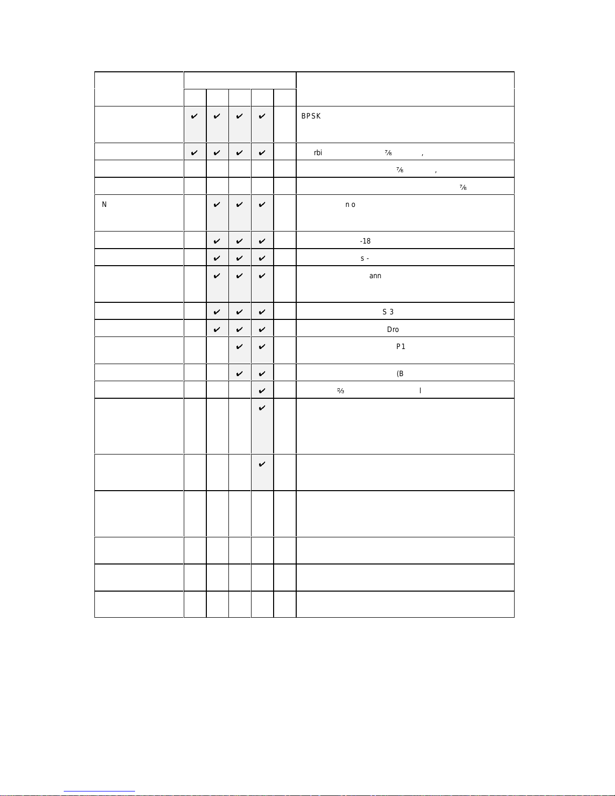
2.3 FEATURE SUMMARY
Feature
* means h/w option
P300 Series Configuration
Description
VSAT IBS IDR TCM USER
Base Modem
UUUU
BPSK/QPSK/OQPSK, 4.8kbps to 512 kbps modem
RS422 / V.35 / RS232 interface with 25 & 37 pin connectors
50MHz - 90MHz IF interface with 100Hz resolution
Viterbi FEC *
UUUU
Viterbi FEC, rate ½, ¾, & f in BPSK, QPSK and OQPSK
Sequential FEC * Sequential FEC, rate ½, ¾ &
f
in BPSK, QPSK, OQPSK
Turbo FEC (TPC) * Turbo FEC, various preset code rates (inc ½, ¾,
f
& 0.789)
INTELSAT
UUU
Reed-Solomon outer FEC, with n, k, t = 126, 112, 7
Reed-Solomon (switching to 225, 205, 10 or 219, 201, 9 with 4/8 deep
interleaving as required for IDR & TCM/IDR)
Wideband IF
UUU
Wideband 50MHz-180 MHz IF (instead of 50MHz - 90MHz)
High Da ta Rates
UUU
Data rates 512kbps - 5Mbps in addition to Base Modem rates
Async ESC
UUU
Variable rate ESC channel for Closed Net plus ESC operation
High rate IBS/SMS ESC (with IBS/SMS featu re)
Async access to IDR 8k sync ESC channe l (with IDR option)
IBS/SMS
UUU
IBS/SMS framing (to IESS 309)
Drop/Insert
UUU
Normal T1/E1 linear order Drop/Insert
IDR *
UU
IDR operation (to IESS 308), P1348 Emulation &
32/64kbps Aux data in place of one/both IDR audio ESC
PRBS Tester
UU
Internal Bit Error Rate Tester (BERT, overhead modes only)
8PSK/TCM
U
8PSK with b rate Trellis Code Modulatio n (to IESS 310)
Extended D/I
U
Independent timeslot re-ordering on Tx & Rx
Signalling (CAS for E1 & RBS for T1)
Rx Partial Insert for multi-destinational working
Timeslot ID maintenance for N=1 to 31 with IBS/SMS or Closed
Net plus ESC operation
Custom Features
U
Arbitrary `n` & `k` for Reed-Solomon (with RS feature)
Custom & Min O/H modes (with IBS/SMS or IDR options)
Custom allo cation of IBS o/h between ESC / Aux channels
Monitor/AGC * Demod Rx carrier signal le vel monitor
0-10V Analog output of carrier signal level, Eb/No, or Rx offset
frequency (in addition to normal AGC output)
Constellation monitor port
AUPC Automatic Uplink Power Control
(requires Async ESC feature to operate)
1544kbps G.703 * 1544kbps G.703 interface in addition to RS422 / V.35 / RS232
interface (software selectable)
2048kbps G.703 * 2048kbps G.703 interface in addition to RS422 / V.35 / RS232
interface (software selectable)
Options marked wi th an as teri sk w i ll require boards or single IC’s to be added to the unit in order to add t he
option at a later dat e. Feat ures w i thout an ast eri sk can be added by ent ering a “Feature Code” into t he front
panel of the equipment.
Page 12

P300H P300 Series Modem Installation and Operating Handbook Page 12
2.4 FEATURE HIGHLIGHT
This list highlights some of the notable features about t he P 300 Series Modems:
Al l P300 Series Modem s (ie base modem features)
U
Variable data rate in 1 bps steps with fast acquis ition ev en at low data rates
U
BPSK, QPSK, and Offset QPSK (OQPSK)
U
Viterbi FEC (to IESS 308/309), rate ½, 3/4 & 7/ 8 in BPSK, QPSK and OQPSK.
U
100Hz IF resolution
U
RS422, V.35, and RS 232 DCE interface on both EI A 530 25 pin and RS449 37 pin connectors .
U
Can accommodate Viterbi & Sequential FE C s imultaneously
U
Built in 1-FOR-1 Redundancy Controller (requires only cables, passive IF splitter/combiner &
second modem for complete 1:1 in just 2U)
U
0-99ms Doppler/plesiochronous buffer
U
Full remote M&C
U
1000 event traffi c log, wi th facility to continuously log circuit performance at regular intervals (logs
average & w orst case Eb/No and/or user B ER)
U
`In The Rack` upload of revis ed internal software
U
25dB Tx IF level control in 0.1dB s teps
U
Band limited IF input capable of operating with high composit e power (ie IF input not `wide open`
and affected by out of band signals)
U
1PPM internal frequency & clock reference, with external station clock input & options for higher
stability int ernal references
U
CCITT & INTELSAT V.35 scramblers for closed network operation, with addit ional two modes for
compatibility with FDC and Linkabit proprietary patterns.
U
Deferred alarm at user set service limits (individual Eb/No, BER & Buffer slip t hresholds)
U
Frequency locked clock loops (ie not phase locked) immune to clock hits caused by equipment
such as routers
U
Comprehensive monitoring and status display, with explicit fault descriptions of most significant
fault for Tx & Rx paths
U
P500 1-FOR-N Switch avai lable allowi n g mixed interfaces withi n 1:N system
U
Supported by A lphawav e CAM multi-product remote M&C system which can provide centralised
log gathering on a PC (including logged circuit performance figures, eg Eb/No every 10 mins )
U
Soft ware includes two `User Variables` to accomm odate custom user requirements (such as
special alarm handling), allowing s pecial user requested features to be added w hilst still keeping
common software
U
Clea r display, in tuitive menus wit h `Normal` selections & efficient user interface with full keyboard
U
Tx or Rx paths may be selected as `Off`, muting appropriate alarms in Tx or Rx only applications
U
Thre e form `C` relay s providi ng prompt Tx/Rx Traffic faults, as well as a prompt unit (equipment)
fault and a deferred alarm.
Page 13

P300H P300 Series Modem Installation and Operating Handbook Page 13
P300 / P310 -IBS Add itional Features
U
INTELSA T Reed-Solomon Feature
A fully INTELSA T compliant Reed-Solomon Codec providing
i
Automatic selection of appropriate INTELSAT values of `n, k & t` and interleaving depth for
data ra te & ser vice selected (n, k, t = 126, 112, 7 by default, switching to 225, 205, 10 or 219,
201, 9 with 4/8 deep interleav ing as required for I DR & TCM/IDR)
i
Provides improved low Eb/N o per formance in framed mode due to use of extended threshold
frame sync algorithms
i
Enhanced capabilities wit h the `Custom Features` feature (see later)
U
Wideband IF Feature
The extension of the 50MHz - 90M Hz IF range up to 50MHz - 180M Hz
U
High Date Rate Feature
The extension of the data rate range to include rates above 512kbps up to 5.0Mbps (depending
on modulation and FEC modes)
U
Asyn c E SC Feature
The addition of a hi gh rate async ESC channel, which may be int ernally li nked t o the M&C port to
provide control of distant end equi pment (i n all ov erhead modes) without additional cabling. The
Asy nc ESC feature provides as follows:
i
Support for any as ync ESC r at e in Close d N e t P lu s ESC mode, providi ng a scalable overhead
which adds the minimum possible overhead to the satellite data to provide the baud rate
selected (adding from <1% to 100% ov erhead). Closed Net Plus ESC mode also provides an
optional backward alarm facility and above 32kbps a synchronous s crambler to replace the
normal error multiplyi ng V.35 self synchroni sing scrambler.
i
A high rate async ESC channel in IBS/SMS overhead, achieving 2400 Baud with a 64kbps
carrier (requires IBS/SMS feature, standard on P300-IBS and above)
i
As ync access to the IDR 8kbps synchronous ESC channel. (requires IDR option, s t andard on
P300-IDR and above)
i
Software selectable RS232, RS485 or RS422 interface.
U
IBS/SMS Feature
Satellite Framing i n accordance with IBS (t o IESS 309) and SMS (EESS 501), including:
i
User assi gned Tx , and corresponding Rx display of, Stat ion ID, Channel ID & Spare ID wit h in
SMS overhead to aid carrier identificat ion.
i
A high rate as ync ESC channel in I B S/SMS overhead (see Asy nc E S C above)
U
Drop/In sert F eatur e
The most sophisticated Drop/Insert functions of any satellite modem whilst still maintaining
simplicity of configuration and operat ion. The Drop/Insert feat ure provides:
i
1544 kbps T1-D4 & T1-ESF and 2048 kbps G.732 operation
i
Arbitrary & independent timeslot selection for Drop & Insert
i
Full support for CRC-4 in G.732 mode and CRC-6 in T1-ESF mode
i
Terrestrial error monitoring based on Frame Alignment Words (FAW) or CRC
i
G.732 `E bit ` proces s ing, allowing the di splay of the outbound terrest rial error rate
i
Loopthrough or generation of local bearer onto which t o insert the Rx data from any normal
clock source (eg station clock, clock from satellite, internal clock)
i
Automatic generation of backup bearer so Rx traffic is not lost if Drop bearer into Tx fails and
bearer is looped through to the Insert mux to pick up Rx dat a
i
Timeslot ID maintenance ev en with Closed Net Plus E SC carriers
i
Enhanced features with the Extended D/I Feat ure (see later)
Page 14

P300H P300 Series Modem Installation and Operating Handbook Page 14
P300 / P310 -IDR Addi tional Features
U
IDR Opti o n
Satellite Framing i n accordance with the IDR specification (to IESS 308), includi ng:
i
Standard IDR framing with 2 x 32 kbps ADPCM audio ESC, a sy nchronous 8kbps ESC data
channel, and four backward alarms
i
Enhanced features with the ‘Custom Features’ feature (s ee later)
i
Independent ES C & A ux Ports to replace the shared ESC/A ux port of the base modem. The
ESC and Aux ports are active in all framed modes. They provide the following features: :
'
ESC Port provides a front panel selectable RS232, RS422, or RS485 interface. In IDR
Mode it provides either a sy nchronous interface to the 8kbps I DR E SC channel, or (if the
Async ESC feature is available, standard on P300-IBS and above) an async inter f ac e
supporting up to 4800 or 9600 Baud eg for distant end M&C via the IDR overhead. This
same E SC port, although part of the IDR option, in Closed net Plus ESC o r IBS/SMS
modes pr ovides a high rate asynchronous ESC interface (eg 2400 Baud at 64kbps in
standard I B S/SMS mode, any Baud rate for Closed Net Plus ESC). A gain typi cally used
for distant end M&C vi a the overhead.
'
Aux Por t provi des a front panel selectable RS232 and RS422 interface. In IDR Mode it
provi des synchronous 32 or 64 kbps channel in place of one or both the 32kbps ADPCM
ESC audio channels. I n I BS/SMS & Minimum Overhead modes it provide a synchronous
port which can be configured to use from 1/32 to 21/32 of the IBS/SMS overhead (eg for
internal or ex t ernal BE R testing). When set t o 1/32 and used asynchronously it provides
the INTELSA T compliant Low Rate E SC channel.
U
PRBS tester feature
The internal Pseudo Random Binary Sequence (PRBS) Bit Error Rate Tester (BERT) offers the
following features:
i
PRBS can pass through the main data channel, or the ESC or Aux channels of the overhead
in parallel with the main data channel i n any mode where overhead is added.
i
BE RT results can be logged in the traffic log at user set intervals, providing continuous traffic
quality monitori ng and recordi ng when operat ing t hrough the overhead in parallel with the main
data.
i
Compatible with pat t erns used by tes t equipment such as the Firebird etc.
Page 15

P300H P300 Series Modem Installation and Operating Handbook Page 15
P300 / P310 -TCM Additional Features
U
8PSK with b rate TCM (50% bandwidt h of QPSK ½ rate Viterbi)
U
Extended D/I Feature
The extended Drop/Insert provides significant extra features compared to the basic Drop/Insert
feature set:
i
Arbitrary & independent timeslot re-ordering for Drop & Insert
i
Full support for G.732 Channel Associ at ed Signalling (CAS) ov er IBS/SMS links
i
T1-D4 & T1-ESF Robbed Bit Signalling (RBS) maintenance over IBS/S MS links
i
Maintenance of timeslot ID for N=1 to 31 inclusive when using any framing (normal ly only
N=1 , 2 , 3, 4, 5, 6, 8, 10, 12, 15, 16, 20, 24 are maintained for IBS/SMS and there is no ID
maintenance for IDR)
i
Insert ion of only partial received data (for multi-destinat ional working)
U
`Custom Features` Featu re
With respect to the Reed-Solomon, the Custom Features provides:
i
Codeword length (`n`) variable from 60 to 255
i
Error correct byt es (`t`) vari able from 2 to 20 in s t eps of two
i
Selectable 4 and 8 depth interleav ing
With respect to the Framing, the Custom Features provides:
i
Custom IDR Modes including 16kbps ADPCM mode providing all normal IDR facilities in a
64kbps overhead, or all normal IDR facilit i es plus a 32kbps Aux channel i n t he normal 96kbps
overhead (which allows an internal or external PRBS test to run in parallel with the traffic to
monitor the service quality). The overhead can also be reduced to provide reduced IDR
faciliti es with 64kbps or 32kbps overheads.
i
Custom IBS/ SM S modes i ncluding facili ti es for multidestinational IBS carriers with 4 backward
alarms, and Mini mum Overhead modes (a more configurable vers ion of Closed Net Plus ESC)
where the overhead varies from the standard 16/15 (6.7%). In minimum overhead mode the
user sets the required ESC Baud rate and the overhead is scaled to the minimum value to
provide the service required. For ex ample 2048kbps wi th 9600 B aud E S C in overhead of <1%,
or 64kbps data wi th ESC rates up to 38.4kBaud
With respect to the ESC Channels
i
Ful l user allocation of the overhead between ESC and Aux channels in IBS/SMS modes,
pro viding user c ontrol over the relative rates of the async ESC channel and the sync Aux
channel.
Turbo Product Code Forward Error Correction (TPC FEC))
U
Turbo codec for bandwidth and power efficiency
U
Software can support up to 31 preset code rates (initial rates includes rate ½, ¾, f & 0.789)
U
¾ Rate for compatibili ty wi t h industry De-Fact o Turbo.
U
½, ¾ & f Rat e al lo w s w itch to Tu r bo & b e t t e r ma rg in / quality of servi ce than Vit erbi in same space
segment (eg fix ed capacity on long lease)
U
0.789 rate prov ides optimised performance near 3/4 rate for newer circuits.
Monitor / AGC Option
U
Monitor and display of Rx carrier level
U
Rear panel PSK constellation monitor point
U
An uncommitted 0-10V DC analogue output, set from the front panel to output AGC/ Signal level
(for antenna pointing / tracking), Eb/No, user BER or any other parameter av ailable internally.
Au to Up link Power Control (AUPC) Feature
U
AUPC via async ESC channel on IBS/SMS, IDR and Closed Net Plus ESC carriers (ie overheads
down to <1%).
U
Automatically Interleaves AUPC with dis tant end remote M&C (if active) on ESC channel.
U
Monit o r only option for distant end Eb/No & BER monitoring without power control.
U
Adds opti onal automati c regular logging of AUPC delta power and distant end Eb/No.
U
Uni-directional, bi-directional and broadcast (Tx only / self monitor) modes.
Page 16

P300H P300 Series Modem Installation and Operating Handbook Page 16
3 DESCRIPTION
3.1 OPERATION
The P300 Series modem are fully software controlled and with t he exception of the optional G.703 interface
option there are no links or switches used to configure t he unit. This enables all control and configurati on
to b e p er form ed either locally from the front panel, or by remote M&C. Local control is by front panel
keyboard, and a large, easy to read, 80 character LCD display, with clear, intuitive menus for configuration
and control. All the set-up parameters are stored in non-volatile mem ory which will retain data for a
minimum of 3 years, with no power applied. The receive and transmit functions of the Modem are
independent, so that they may be operated at a different data rates, IF frequenci es , or different services if
required.
Like al l Par ad ise Datacom products, the P300 Series includes a traffic log which stores the last 1000
events , s uit ably ti me-stamped. It can automatically add s ev eral measured parameters to the log at operator
set i ntervals, including average & w orst case Eb/No, average & worst case es timated user BER, average
& wor s t ca se estimated uncorrected BER, and the buffer fill state. The logged perform anc e monitoring
allows inves t igation into cus tomer reports of poor link performance, and can provi de a useful correlation
against weather conditions , etc.
3.2 FAULT PHIL OS OP HY
Faults are split into two categori es:
a) UNIT FAULTS: Equipment failures (such as a synthesiser lock failure).
b) TRAFFIC FAULTS: Data path failures, (such as a lack of input clock).
A full description of every detected fault, its category (unit or traffic), and the corresponding action taken
is pr ovided in Appendix G - Fault Messages and Action Table. The response of the front panel LED
indicat ors and external fault relays respond is des cribed in the following sections.
3.3 ELECTRI CAL DESCRIPTION
The P300 modem com prises of a single main modem Printed Circuit Board (PCB) with four optional
additi onal boards:
'
Optional G.703 i nterface (two different boards for T1 or E1 operation).
'
Optional I DR E SC board which provides for all the IDR ESC requi rements
'
Optional Monitor / AGC board which provides a user scalable AGC output and a constellation
monitor point.
'
Optional Turbo FEC daughtercard
For the P310, an L-Band daught erboard is also fitted internally above the main modem board, and further
three internal options are possible:
'
Reference oscillator options (several of varying stabilities)
'
An internal 100W PSU to provide a DC feed to an external BUC
'
An optional FSK com munications board, to enable a modem and BUC to bo operated from the
modem front panel (and to provi de closed loop power cont rol to t he BUC flange).
Page 17
STATUS
RX OK
TX OK
TEST
STANDBY
DATACOM
PAR AD ISE
Tx path OK for 3.7days
Rx path OK for 2.1days BER < 1E-12
0
1 2
3
4
5 6
7
9
8
YES /
ENTER
NO /
PREV
MAIN
P300 Series
Satellite Modem
STATUS
RX OK
TX OK
TEST
STANDBY
Status LEDs
Green:
Red:
Green:
Off:
Green:
Off:
Off:
Amber:
Off:
Amber:
Modem itself OK
Modem internal fault
Rx traffic OK
Rx traffic fault (external to modem
)fic fault (external to modem)
Tx traffic OK
Tx traffic fault (external to modem
)fic fault (external to modem)
Normal
Loopback or Test mode active
Normal (Tx carrier on)
Tx carrier off or Standby of 1:1
P300H P300 Series Modem Installation and Operating Handbook Page 17
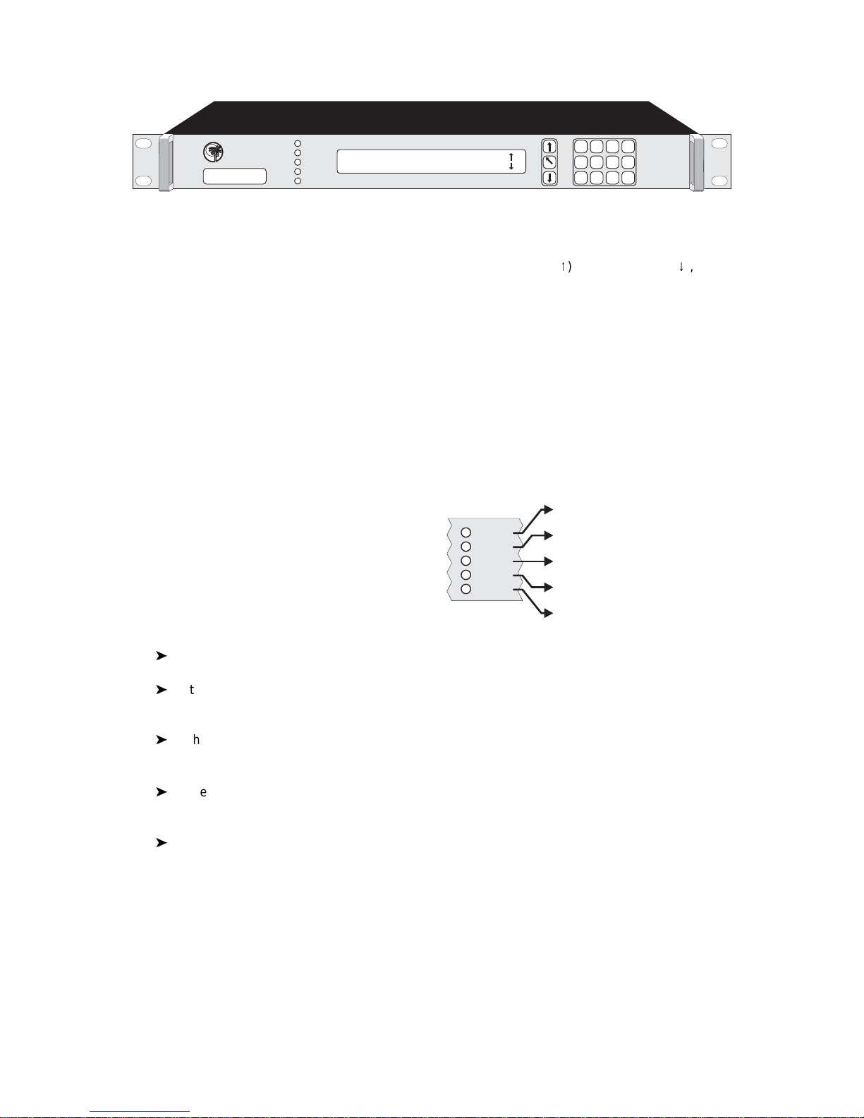
P300 Modem front panel view
3.4 FRONT PANEL FEATURES
Keyboard
The keyboard is of t he membrane type (an integral part of the front panel) which provide a direct tactile feel.
There are 15 keys in t otal - number keys i n t he range 0 to 9, an up arrow key (
8
), down arrow key (9), MAIN
key, YES/ENTER key , and NO/PREV key.
LCD display
This backlit dis play provides 2 lines of 40 characters each and is hi ghly legible even in conditions of high
ambient light. The LCD provides detailed information about the status and configuration of the unit, and
when appropriate, prompts the user to enter data via the keypad.
Monitor port
The circular m onitor port available on the front panel of previous products has been moved to the rear
panel and is now combined onto the A sync ESC connector (a `D` type connector instead of the difficult to
obtain 8 p in `din` audio type connector). S ee t he description of the “Async ESC connector” under the rear
panel description which starts on the next page.
LED Indicators
Five LEDs on the front panel provide summary fault
in format ion, so that even w hen the LCD is unavailable
for status display (such as when the operator is
rec on f iguring the unit, and a menu is displayed), the
cur r en t status can always be assessed. If any of the
LED's indicat e a fault, press MAIN, then select Status
to display the current fault condition.
'
In normal operation there should be three GREEN LED's showing.
'
If the St a tus is RED, the unit has failed due to internal or possibly external conditions. Refer to
the text on the LCD Status screen and rectify if possible.
'
If the TX OK or RX OK L ED's are off, then the Tx or Rx tr affic has failed due to an external fault,
again refer to the text on the LCD Status screen and rectify if possible.
'
If the TE ST LED is AMBER, a test mode or loopback is active, press MAIN, and select Test to
query or change the test settings.
'
If the STANDBY LED is Amber, the Tx carrier is off. It may be i ntentionally switched off, or it may
be muted due to either a fault, an external mute signal, or if in a 1-FOR-1 redundant pair it may be
the standby unit.
Page 18
MULTI STANDARD INTERFACE
P1440A
1998
PARADISE DATACOM
S/N
1097
This text so coreldraw doesn’t crash on export !
ESC, AUX &
BACKWARD
ALARMS
IN OUT
E1
75R
Tx IFRx IFSTATION CLOCK REMOTE M&C
1 FOR 1 ALARMS & AGC
ASYNC ESC
100-240Vac
0.3-0.1A
50/60Hz
P300H P300 Series Modem Installation and Operating Handbook Page 18
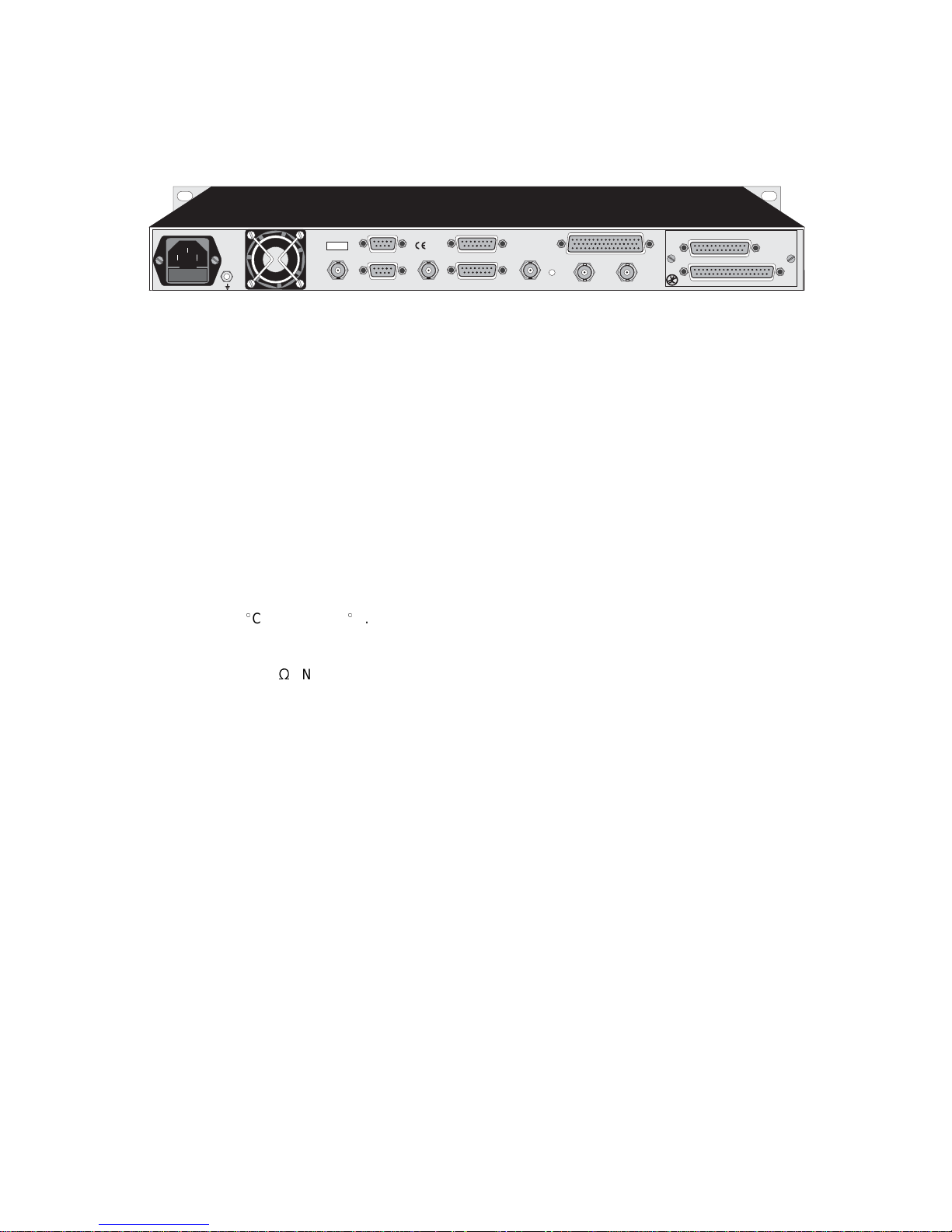
P300 Modem rear panel view (IDR & G.703 options fitted)
3.5 REAR PA NE L DESCRIPTION
At the rear of unit are all of the connectors necessary for the user to interface the Modem to the outside
world; IF input and output to frequency conversion equipment, terrestrial data connection, station clock,
alarms & AGC output, remote M&C, AC power and so on.
From left to right, the rear panel connectors are:
IEC mains power connector/voltage selector/fuse
The Modem is desi gned to operate from a mains AC supply of 100-240V (-15% + 10%, ie 85V to 264V at
the connector). The IE C connector i ncorporates t w o fuses, independently fusing both live and neutral lines .
Acc ess to the f uses are provi ded by a slide out tray. Bot h fus es are standard 20 mm type, rat ed 2A, of the
slow -bl ow (time delay) type. ALW AYS REPLACE THE FUSE WIT H ONE OF THE SAME TYPE AND
RATING.
Chassis ground stud
This is an M4 stud for connecting a safety earth conductor di rect ly to the chassi s of the unit.
Fan
The fan may be selected to be temperature controlled or permanently active (ie the fact that it is not running
does not indi cat e it has fai led). Us e the t est menu to display the internal unit temperature if in doubt, the fan
comes on at 26
E
C and off at 24EC.
Station Clock
This connector is a 75
S
BNC femal e wh ich accepts a 1-10MHz signal, either a square wave of >1V p/p (eg
a G.703 para 10 `synchronising clock`) or a sinusoid at a power level of 0dBm or greater. An alternative
Stati on Clock signal at RS422 interface levels can be applied to the Async ESC connector. E ither signal
can be used by t he modem as a reference for the receive out put clock (the Station Clock does not have
to be the same r ate as the data as an internal PLL converts bet ween rates). In addition if t he Rx Clocking
is set t o us e th e “Statio n Clock” and the Tx Clocking is se t to “Rx”, t hen t he Station Clock also sources the
int ernally generat ed Tx Clock (Tx & Rx data rates are independent). Finally, if a 10MHz s ignal is applied,
this signal may also be used in place of the int ernal reference for the Tx and Rx IF synthesisers.
1:1 Redundancy connector
The Modem has a built-in 1 for 1 redundancy controller which connects to the corresponding port of
another Modem via this 9 pin m al e 'D' type connector. A com pl ete 1:1 redundancy system requires only
two modems, a 1: 1 control cable (on this port), a data split (`Y`) cable, and passive sp li tters/combiners for
the IF port s (or s plit ters /combiners already pres ent i n t he sy s tem). Connection detai ls are given in A ppendix
B, and an overview of 1 for 1 operation is provided in s ect ion 9 starti ng on page 163.
Remote M&C con n ecto r
This is a 9 pin female 'D' type connector whose pinout and interface levels are `SA-bus` compliant. The
Modem can be set to operate with either Paradi s e/FDC or SA-bus protocols. The electrical i nt erface can
be s elected between RS232 (for direct to PC applications) & RS485 (for mul tidrop applications). The
Remote M&C port may be internally linked (i e no cable s) to t he Async ESC port for over the satellite distant
end Remote M&C control. Pi nout details are in A ppendix B.
Page 19

P300H P300 Series Modem Installation and Operating Handbook Page 19
Rx IF input
This connector is a BNC female and can be used as either a 50
S
or 75S input. The allowable signal level
of the desired carrier at the input of the modem is from -60dBm to -30dBm (P310: -70dBm to -20dBm). A
level of -45dBm is recommended. The maxi mum composite power level that should be applied to this port
is 30dB above the desired carrier, up to a maximum of 0dBm (P310: Composite +35dBc to max of 10dBm).
Alarms and AGC connector
This is a 15 pin m ale 'D' type connector that provides access to the three form `C' relay contacts that
indicate alarm conditions. Also provided on this port if the Monitor/AGC option is fitted is an uncommitted
analog output which by default provides an AGC output, but which may be selected via the front panel to
pro vide other user requested signals (eg Eb/No, Rx IF offset frequency, or other uses implemented as
required). The alarm relays have t he followi ng definitions :
Unit Fault:A unit fault exists, i.e. an equipment failure.
Traffic Prompt: A Tx or Rx traffic fault exists.
Deferred alarm: One of the following conditions exists :
The receive BE R is greater than the user defined threshold.
The receive Eb/ No is lower than the user defined threshold.
Buffer slips are more frequent than the user set threshold.
A Backward alarm is being received from either the satellite or terrestrial
ports.
Full pinout details are provided in Appendix B. The alarm relay functions can be changed, See `Relay
Mode` in appendix E.
Asyn c E SC connector
This 15 pin `D` female connector provides a superset of the features found prev iously on the front panel
circular 8 pin `din` connector. It includes an RS232 serial port for the loadi ng or revised internal software
from a PC or the printing of the uni ts traffi c log to a serial printer / PC terminal emulator. If the Monitor/AGC
option i s fi tt ed i t prov i des I , Q, and sy mbol clock outputs to monitor the receive constellation (in order to view
received signal quality on an oscilloscope). When the IDR option IS NOT fitted, it provides an
RS232/RS422/RS 485 asynchronous port for either the high rate Async ESC facility (for IBS/SMS or Closed
Net Plus ESC services) or the IBS/SMS `low rate INTELSAT oversampled ESC facility` (which is configured
as the Aux data channel on the modem). When the IDR opt i on IS fitted, separate port s for the ESC and Aux
channels on the IDR card are acti v at ed, and ESC/Aux access on this async port is disabled. Finally, this
connector also provi des t he port for an RS422 compatible Station Clock (see the Station Clock paragraph
on the previous page).
Tx IF output
This connector is a BNC female and can be used as eit her a 50
S
or 75S output. The output pow er level
can be varied from 0dBm to -25dBm on 0.1dB steps from the front panel (P310: -5dBm to -30dBm).
ESC & Aux connector
This connector is fi t ted as part of the IDR option (Standard on P300-IDR & P300-TCM), it provides access
to:
'
Four ba ckwa rd al arm form `c` outputs, and the 4 backward alarm inputs, together with a Rx
summary alarm signal for direct connection to t he backw ard alarm inputs . Note that these can be
used both in ID R modes, and (i f t he IBS and `Custom Features` features are available) a custom
IBS mode which allows four backward alarms for low rate IBS multidestinational carriers.
'
Two Audio ES C ports (4 wi re 600S, +7 to -16dBm). In addit ion to normal IDR ESC operation these
por ts ma y also be used in IBS m odes to generate a 64kbps IBS carrier comprising just the two
32kbps ADPCM audio channels, or a 128kbps IBS carrier comprising 64kbps data (from the main
data interface of the modem) plus the two 32kbps ADPCM audio channels. This is an emulation
Page 20

P300H P300 Series Modem Installation and Operating Handbook Page 20
of the most popular modes of the P1348/P1448 voice/data mux card used often in SNG
applications.
'
An RS232/RS422/ RS485 P o rt for s ync/asy nc E SC traffic, this port replaces the shared ESC/Aux
access via the Async ESC connector on the main unit. Used to provide access to the 8kbps
synchronous I DR ES C channel. I f the Async ESC feature is avai lable (standard on P 300-IBS and
above) t hen Async access to the 8kbps channel is also available. Again if the As ync ESC feature
is avai l able this port also provides the high rate Async E SC on IBS/SMS or Closed Net Plus ESC
services
'
An RS232/RS422 port for s ync/async Aux traffi c, this port replaces the shared ESC/Aux access
vi a the A sync ESC connector on the main unit.. The Aux port provides 32 or 64kbps access to the
IDR overhead in place of one or both of the IDR 32kbps ADPCM Audio ESC channels. If the
IBS/SMS feature is available then this port may be confi gured t o provide either the IB S `low rate
INTELSAT oversampled ESC facili ty`, or a higher rate synchronous channel wit hin the IBS/ SMS
overhead.
Pinout det ails are provided in Appendix B.
Terrestrial Interface Connectors
The P300 provides as s tandard bot h 25 pi n EI A 530 and 37 pin RS449 female DCE connectors. NOTE t hat
these are si mply wi red i n parallel and you should not connect both simultaneously. The electrical i nterface
is fr ont panel selectable to be RS422, V.35, and RS232. Normally for RS232 operation the EIA530
connector would be used (which is standard 25 pin RS232 compatible) and for RS422 the 37 pin RS449
connector. The old style 34 pin `Winchester` connector favoured for V.35 interfaces has poor EMC
performance and so could not be incorporated whilst maintaining CE compliance. If this style of connector
is required then an external adaptor cable must be used.
If the G.703 opti on is fit ted, then in addition to RS422/V .35/RS232, G.703 is also available as a softw are
selectable interface standard. T1 (1544kbps) G.703 i s a balanced 100
S
signal, and i s provided on both `D`
type connectors when G.703 is selected from the front panel. W hen the E1 (2048kbps) G.703 option is
fitted then in addition to providing support for the balanced 120
S
signal on both `D` type connectors an
additional pair of BNC connectors are provided to accept the unbalanced 75
S
interface standard. THE
SELECTION BET WEEN 75
S
and 120S IS MADE BY A SWITCH ON THE E1 G.703 OPTION not by
software. A s w i th the 25/ 37 pi n connectors, do not connect s i gnals to both the BNC and `D` type connectors
simultaneously.
In addit i on a sw i tch on both t he T1 and E1 G.703 options controls what happens to the G.703 port when
power is removed. Either the G.703 ports can be set to go high impedance (used in 1:1 redundancy
operation) or it can be configured to loop the G.703 input back to the output (typically used when
Drop/Insert is in operation and the same PCM bearer is cas caded t hrough several modems). Agai n (as it
affects what happens when power is removed) this is SET BY A SWITCH ON THE CARD not by software.
Finally, for special customer requirements it is possible to fit a different interfaces to this port. Note that
UNLIKE P REVIOUS PRODUCTS the interface does NOT simply unplug. I nstead it is cons tructed as part
of the m ain m odem, and requires `snapping off` and a connector to be soldered in place before a
replacement card can be fitted.
Standby LED
This LED mirrors t he front panel standby LE D, so that from the rear of the equipment the operator can tell
if the carrier is off, or more importantly which unit of a 1:1 pair i s the offline unit.
Page 21
RS422/V.35/
RS232
+G703
OPTION
INTERFACE
RS449/
EIA530/
TWIN BNC
DATA PORT
Sync/Async
ESC.PORT
(sync with
octet timing)
Dual 4 wire
audio
interface
Sync/Async
aux port
(Sync with
Octet timing)
“Async port”
IDR
ESC
OPTION
RS232/422/
485 INTERFACE
INSERT
MUX
UART
SYNC
PCM
32K
ADPCM
AUX
OUT
DPLL
BLANK PCM
FRAME GEN
Rx
BUFFER
Tx
PLL
Rate
Convert
DEFRAMER
From FEC/Demodulator
FRAMER
INTERLEAVER
To FEC/Modulator
RS
DECODER
RS
ENCODER
INTERNAL
BER
TESTER
Tx
FIFO
DROP
MUX
Rx
CLOCK
DE-
INTERLEAVER
Rx
PLL
AUX
AUX
ESC
ESC
STATION
CLOCK
Tx CLOCK IN
Tx CLOCK IN
T1000 ASIC
INTERNAL
1PPM
INTERNAL
1PPM
3P
3P
3P
3P
2P
2P
IDR OPT
FITTED
IN
OUT
INT
CLK
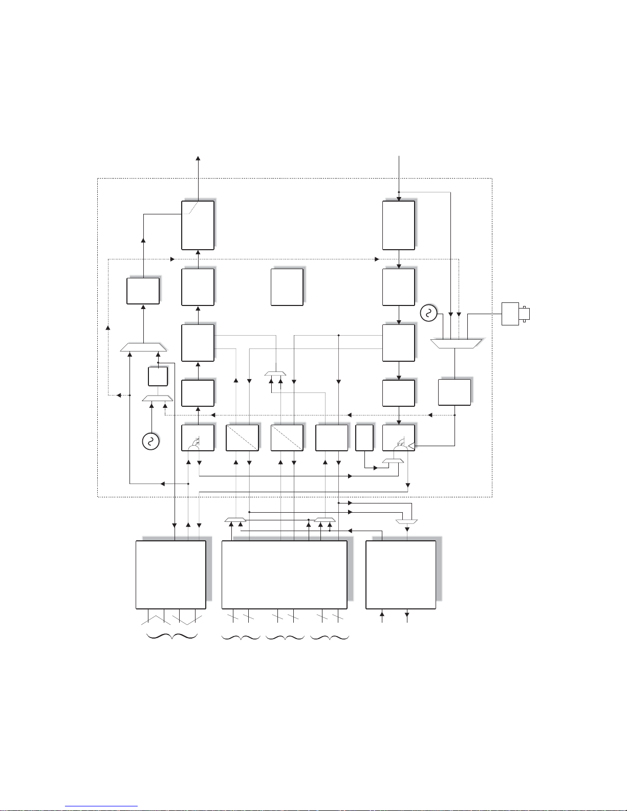
P300H P300 Series Modem Installation and Operating Handbook Page 21
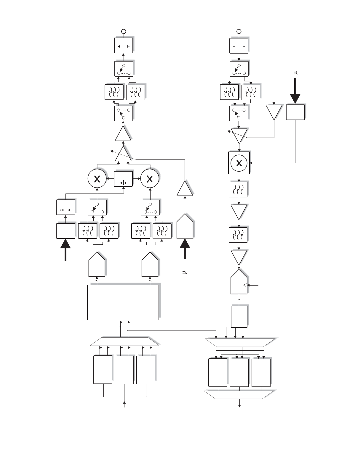
3.6 BLOCK DIAGRAM
Page 22
AMP
OUTPUT
MATCH
VCA
ANTI-ALIASING
LPF's
SWITCHED LPF
FILTER BANK
Tx O/P POWER
LEVEL CONTROL
DAC
4
2
1
DAC
DAC
8
I
I
8
Q
Q
DAC
Tx PLL
SYNTH
TURBO
SEQ
SEQ
TURBO
VIT/TCM
VIT/TCM
50 MHz
SAW BPF
ADC
DIGITAL
DEMOD
10
5dB
AMP
AMP
INPUT MATCH
LPF
AGC
DOWN
CONVERT
MIX
SWITCHED LPF BANK
P
P
Rx PLL
SYNTH
INTEGRATOR
From
Interleaver
To
Deinterleaver
DUAL
FIR
FILTERS
P300H P300 Series Modem Installation and Operating Handbook Page 22
Page 23

P300H P300 Series Modem Installation and Operating Handbook Page 23
4 SUMMARY OF SPECIFICATIONS
Common Main Sp ecifications
Optional features are shown in [square brackets]
Modulation BPSK, QPSK, OQPSK, [8PSK]
Frequency/Resolution P300: 50 MHz - 90 MHz, 100Hz resolution.
[50 MHz - 180 MHz Wideband IF feature]
P310: 950MHz - 1750MHz 100Hz resolution
[950 MHz - 2150 MHz Wideband IF feature]
Traffic Interface
Electrical RS422, V.35 and RS232 software selectable (clocking can provide X.21
DCE or DTE mode)
Mechanical Both EIA530 DCE and RS449 DCE connectors (25 pin and 37 pin `D`
female respectively) .
Options T1 or E1 G.703 in addition to RS422, V.35, & RS232 (software
selectable)
For special requirements a cus tomer specifi c i nterface card may be fitted.
User Data Rates
Closed Network Resolution of 1 bps
Rate ½ Rate ¾ Rate
f
Uncoded Rate
b
BPSK
min 4.8k 7.2k 8.4k 9.6k
max * 1250k 1875k 2187k 2500k
QPSK / OQPSK
min 9.6k 14.4k 16.8k 19.2k
mix * 2.5M 3.75M 4.375M 5.0M
[8PSK/TCM]
min 19.2k
mix * 5.0M
[Closed Net plus ESC] As Closed Net above but limits include an overhead of approx 1.4 x ESC
Baud rate. Resolution of 1 bps. ESC from 50Baud to 38.4kBaud
[IBS/SMS Mode] <9.6k to >2048k (6.7% overhead added)
*
Resolution of 1 bps
[IDR Mode] <64k to >2048k (96k overhead added)
*
Resolution of 8k (limitation of frame structure)
* Note: Maxim um dat a rat e is 512kbps in all modes before overheads unless the High
Data Rate option is fitted.
Forward Error [Turbo Product Codec (TPC), Preset rates inc rate ½, ¾,
f
, & 0.789]
Correction [TCM rate
b
to IESS 310]
Page 24

P300H P300 Series Modem Installation and Operating Handbook Page 24
[Viterbi, rate ½, ¾, or f, k = 7 to IESS 308/309, 3 bit soft decision
decoding]
[Sequenti al rate ½ , ¾, or
f
to IESS 312, 2 bit soft decision decoding]
Reed-Solomon outer FEC [Concatenated Reed Solomon outer codec to IESS 308/310] [Optional
vari able code rate]
Reed-Solomon, Turbo, TCM, Viterbi, & Sequential are independent FEC options, all
may be fitted simultaneously.
Scrambling
IBS/SMS Synchronised to framing, per IESS 309
IDR & Closed Net With RS Coding: synchronised to RS overhead.
No RS Coding, non Turbo: V . 35 self synchronising.
No RS Coding, Turbo: S y nchronous 2 -1 (sy nc to TPC block alignment).
12
Closed Net plus ESC 32kbps or above, synchronised to ESC overhead. Less than 32kbps, as
per Closed Network.
V.35 scrambler has CCITT, I NTELS AT, `FDC` & `Linkabit `modes
IF Ports BNC female, 50
S
& 75S. Return loss 18dB typical.
External reference Clocking only: 1kHz-10M Hz in 1kHz steps (See Station Reference).
Clocking & Frequency: 10MHz, 0dBm ± 1dB
Modulator Specifications
Output Power Level P300: 0 to -25dBm continuously variable in 0.1dB steps from front panel
or vi a remote control
P310: -5 to -30dBm continuous ly variable in 0.1dB steps from front panel
or vi a remote control
Output Level Stability ±0.5dB at 25
E
C ±10EC
Transmit Filtering 6th order Butterworth, aperture and group delay equalised, INTELSAT
IESS compliant
Filter I m p lementation 257 tap F IR digit al fi lter
Occupied Bandwidth 1.2 times symbol rate
Recommended 1.4 times symbol rate
Channel Spacing
Phase and Amplitude ± 2 degrees, ± 0.2dB, max
Accuracy
Carrier Suppression -30dBc, min.
Output Phase Noise <1.0 degrees RMS double sided, 100Hz to 100kHz
Output Frequency Stability As per internal reference from 0
E
C to 50EC (See Internal Reference
below)
Page 25

P300H P300 Series Modem Installation and Operating Handbook Page 25
Harmonics and Spurious Better than - 55dBc/4 kHz
Transmit On/Off Ratio 55dB minimum
External Transmit Inhibit By external contact closure or by TTL signal applied to rear panel
connector. Hardware functi on overrides processor control
Demodulator Specifications
IF Input Range P300: -45dBm nominal, ±15dB (desired carri er)
P310: -20 to -70dBm (desi red carrier)
Maximum Composite Signal P300: 30dB above level of desi red input up to a maximum of 0dBm
P310: 35dB above level of desired input up t o a maximum of -10dBm
Frequency Acquisition Selectable from ± 1 kHz to ± 32 kHz
Range
Acquisition Threshold < 5dB Eb/No
Acquisition Time @ 9.6 kbps < 3 seconds at 6dB Eb/No
(rate ½ FEC) @ 64 kbps < 2 seconds at 6dB E b/No
@ 2048 kbps < 500 ms at 6dB Eb/No
Clock Tracking Range ± 100 ppm min
Receive Filtering 6th order B utt erwort h, group delay equalis ed (I NTELS AT IESS compliant)
BER Performance In al l case s met in the presence of two adjacent carriers each 10dB
higher than the des ired carrier, with V.35 scrambling
These figures meet or exceed the relevant IESS performance
specifications.
Rate ½ Rate ¾ Rate
f
Rate
b
Viterbi
(all rates)
1 x 10 4.7dB 6.1dB 7.1dB
-4
1 x 10 7.2dB 8.8dB 9.5dB
-8
Sequential
(64kbps)
1 x 10 4.3dB 5.4dB 6.4dB
-4
1 x 10 6.4dB 7.3dB 8.6dB
-8
Sequential
(2048kbps)
1 x 10 5.6dB 6.1dB 6.9dB
-4
1 x 10 7.5dB 8.1dB 8.4dB
-8
Turbo (TPC, QPSK)
(all rates)
1 x 10 2.6dB 3.5dB 6.0dB
-4
1 x 10 3.7dB 4.5dB 8.3dB
-8
8PSK/TCM
(all rates)
1 x 10 6.3dB
-3
1 x 10 10.4dB
-8
8PSK/TCM + Reed- 1 x 10 6.1dB
Solomon
(all rates)
-4
1 x 10 7.3dB
-10
Page 26

P300H P300 Series Modem Installation and Operating Handbook Page 26
BER performance with
concatenated RS BER improvement depends on n and k values chosen, but a typical
increase i n coding gain of 3dB is pos sible over basic Viterbi mode.
Monitor Functions Measured FEC input B E R (raw channel, not TCM)
Esti mated FEC output BER (not TCM)
Measured Reed-Solomon input B E R
Esti mated Reed-Solomon output BER
Measured deframer FAW BER
Measured Eb/No (not based on channel BER, range: 3.0-15.0dB,
accuracy ±0.2dB).
Measured frequency offset (± 100 Hz resolution)
Clocking and Buffering
Clock Loops Frequency locked loops giv e phase hit immune operation even with poor
clock sources such as routers et c.
Tx Clocking Internal Reference (see Internal Reference below for stability)
Ex ternal - tracking range ±100 ppm / min.
Rx Timing - slaves Tx internally generated timing from Rx clocking
whatever Rx clocki ng mode is selected eg with Rx=Satellite for loop
timing (with f ul l a sym m etr ic rat e capability), or with Rx=Station for
both Tx & Rx clocking slaved to Station Clock (again with full
asymmetric rate capability).
Rx Clocking Clock from satellite (Buffer disable)
Tra nsmit input clock - (plesiochronous, includes full asymmetric rate
operation)
Internal Reference (see Internal Reference below for stability)
DCE External timing clock (DTE interface only).
Stati on reference (see below )
Internal Refer en ce P300: +/ -1P PM
P310: Default as per P300. Options: 7x10⁻⁷ per year (P313B), 1x10⁻⁷
per year (P313C), 7. 5x10⁻⁸ per year (P313D).
Station References inputs 75
S
BNC female, transformer isolated 1MHz to 10MHz in 1kHz steps
(accepts sinusoid >0dBm or squarewave eg G. 703 para 10)
120
S
RS422 compatible input, 1kHz to 10MHz in 1kHz steps
When set to 10MHz, t he st ati on reference may replace internal reference
to all internal circuit ry (eg I F s y nt hs). The unit automatically switches back
to the int ernal reference if t he station reference fails.
Buffer Size Selectable in 1 ms increments from 0 to 99 ms. Automatically adjusted
to slip an i nteger multiple of terrestrial multiframe length for framed rates
(T1/E1).
Buf fer st orage is 32kByt es, so above 2.6 Mbps max buffer size reduces
linearly from 99 ms to 52ms at 5.0Mbps
Page 27

P300H P300 Series Modem Installation and Operating Handbook Page 27
Framing & Deframing
Formats Closed Network (unframed)
Closed Net plus ESC [As ync ESC Feature] provides variable rate async
ESC, optional synchronous scrambler above 32kbps to replace error
multiplying V. 35 scrambler, optional backward alarm facility, and optional
Tim esl ot ID Maintenance when used with Drop/Insert, all in minimum
possible overhead down to <0.5%.
INTEL SA T I B S & E ut e lsat S M S [ I B S/ S MS Feature]. Framing to IESS 309
& IESS 310
INTELSAT IDR [IDR Option]. Framing to IESS 308 & IESS 310
Custom Framing [`Custom Features` feature]. Provides custom framing
based on IBS or I DR formats. F or example the use of 16 kbps ADPCM
on the IDR audio ESC channels, providing an IDR carrier with all normal
facilities but with 32kbps of overhead spare for continuous traffic quality
BE R mo nitori ng ( u s i n g b uilt in PRBS t e s t er wi th automatic results logging
or external BERT)
Poor BER performance Deframer includes extended threshold operation which improves
performance when used with Reed-Solomon in v ery poor BER conditions
(where a single uncorrectable RS codeword can contain enough corrupt
frame alignment words to knock an INTELSAT specified deframer out of
frame sync).
[INTELSAT Reed So lomon Codec & Custom Featu r es]
Format Concatenated Reed Solomon outer codec to IESS 308/310
Code Rate Default n, k, t = (126, 112, 7) depth 4, automatically switching to: (225,
205, 10) depth 4 for 1544 kbps I DR mode. (219, 201, 9) depth 4 for 2048
kbps IDR mode & TCM <=1544 kbps, and (219, 201, 9) depth 8 for TCM
>1544 kbps
Processing Delay Combined Encoder & Decoder: 8 x (2n - k + 60)
Combined Interleaver & De-interleaver: 8 x n x depth (Calculate delay
time using dat a rat e including RS overhead)
[Custom Features] When available allows arbitrary selection of `n` & `k` to provide fully
vari able code rate.
`n` = 60-255
`k` = n-2 to n-20 step 2
Interleav ing depth of four or eight
The `Custom Features` Feature allows use of shorter codewords to
reduce interleaver / de-interleaver delay on low data rate circuits. For
examp le switching from n, k, t = 126, 112, 7 to 64, 56, 4 provides
approximately the same correction ability (7 in 126 = 5.5% and 4 in 64 =
6.25% respectively), with similar overheads (126/112=12.5%,
64/56=14.3%), but wi t h i nterleav i ng & decoder delays reduced from 5632
to 3104 bits (156 ms to 85 ms at 32 kbps).
Page 28

P300H P300 Series Modem Installation and Operating Handbook Page 28
[Drop /Insert Feature]
Bearer Types T1-D4, T1-ESF, and G.732.
Timeslot Selecti o n Independent selection of arbitrary timeslots for both Drop and Insert.
Bearer Generation The terrestri al bearer may be looped through the Drop mux then Insert
mux, or terminated after the Drop mux and a new blank bearer
generated by t he I nsert mux . The bearer generated within t he Insert mux
provides full multiframe and CRC support and may be generated from
the Tx Clock, Station Reference, Satellit e Clock or I nternal reference.
Bearer Backup In the e vent that the Insert mux bearer clock is lost, or AIS is supplied,
then the Insert mux will switch temporarily to bearer generation mode in
order to preserve the receive traffic. The backup bearer may be
generated from the Station Reference, Satellite Clock or Internal
reference.
Terrestrial CRC Fully supported, w i th front panel display of t errestrial error rate based on
CRC (T1-ESF and G.732) or Frame Alignment Word errors (all bearer
types)
Timeslot ID Maintenance The IBS /SMS or Closed Net plus ESC ov erhead maintains the ident ity of
individual D/I timeslots for N=1, 2, 3, 4, 5, 6, 8, 10, 12, 15, 16, 20, 24, 30
(see Extended D/I Feature below).
[Extended Drop/ Insert Feature]
Timeslot Re-ordering Se l ected timeslots may be independently re-ordered on both Tx and Rx
paths.
Timeslot ID Maintenance The IBS /SMS or Closed Net plus ESC ov erhead is ex t ended to maintain
the identity of individual D/I timeslots for all values of N from 1 to 31,
including t he previous ly unavailable values N=7, 9, 11, 13, 14, 17 - 19, 21
- 23, 25-29, and 31.
Multi-destinational working All or only a subset of the received data may be inserted into the
terrestrial bearer on the receive path for multi-dest inational worki ng.
Signalling Both Channel Associated Signalling (CAS), and Robbed Bit Signalling
(RBS) are fully supported:
For E1 G.732 Drop/Insert , CA S s i gnalling is extracted from terrestrial
TS1 6 and carried over the satellite in IBS/SMS TS16 and TS48
before re-inserting into the di stant terrestrial TS16
For T1-D4 and T1-ESF RBS the IBS or Closed Net plus ESC
overheads maintain the identity of the in band signalling, and it is
re- inserted into the terrestrial multiframe in the correct positions to
maintain the RBS.
[Async ESC Feature] & Aux Data Ch an n el
Page 29

P300H P300 Series Modem Installation and Operating Handbook Page 29
ESC/Aux Port A single port provides the interface for optional high rate async ESC
(IBS/ SM S or Closed Net plus ESC), or the INTELSAT low rate async IBS
ESC channel.
Electrical Interface RS232, RS422, or RS 485 external interfaces or internal link t o Remote
M&C port (softwar e selected). No external cabling required betw een t he
ESC and M&C ports for M&C via ESC channel within overhead. Other
devices externally wi red in parallel with M&C port can also be accessed
remotely.
Au x Data Ch an n el
IBS INTELSAT low rate async ESC definition carried in bit 1 of TS32
provi di ng a sy nchronous channel at 1/480th of the dat a rate, allowing up
to o ne quarter of this rate for oversampled async data. Compliant with
INTELSAT IESS 403 low rate ESC definition.
[Asyn c E SC Feature]
Closed Net plus ESC Overhead scales to provide any user specified async ESC Baud rate
whatever the sa tellite data rate. ESC limit is approx 70% of main channel
rate, ov erhead varies from <0.5% to >70%
IBS/ SMS High rate as ync data using from 1/32nd to 22/32nd of the IBS overhead,
providing async baud rates from 0.2% to 5.1% of the terrestrial rate (eg
up to >2400 Baud at 64 kbps). Includes modes compatible with the P 400
Series, P230 & P1300/P1361 (using 20/32nd of the overhead).
[IDR Option]
IDR ES C Audio Interface Two 32 kbps ADPCM channels, 4 wire 600S, +7dBm to -16dBm
(software programmable in 0.1dB steps)
Backward Alarms Outputs: F our `form C` relays
Inputs: Four protected inputs, short t o 0 V to send alarm, with matching
summary Rx fai l output. Alarm inputs software configurable for:
a) all external patch
b) 1=Rx fail & 2-4=Ext ernal Patch
c) 1=Rx Fail & 2-4=OK
d) 1-4=Rx F ail.
ESC/Aux Ports When the IDR option is fitted, independent ESC & A ux ports on the IDR
option replace the single shared ESC/Aux port of the base unit .
ESC Port RS232, RS422, or RS485 external interfaces or internal link to Remote
M&C port (softwar e selected). No external cabling required betw een t he
ESC and M&C ports for M&C via ESC channel within overhead. Other
devices externally wi red in parallel with M&C port can also be accessed
remotely. Prov ides Clock, Data, & Sync (Octet timing) lines.
IDR Synchronous access to 8 kbps IDR ESC. With the Async ESC feature
(standard on P300-IBS and above) async ESC access to the 8kbps IDR
ESC is provided, giving up to a 9600 Baud async channel
Page 30

P300H P300 Series Modem Installation and Operating Handbook Page 30
Others IBS & Cl osed Net plus ESC facilities as before installation of IDR option,
but now on ESC port on IDR card not shared ESC/A ux port of base unit.
Aux Port RS232 or RS422 (softw are selected). Provi des Clock and Data lines.
IDR Provides 32 or 64 kbps access in place of one or both Audio ESC
channels.
IBS INTELSAT low rate E SC mode as prev i ously but now via Aux port on IDR
car d no t shared ESC/Aux port of base unit. IDR option also adds sync
IB S mode, configurable to us e between 1/32nd and 21/32nd of the IB S
overhead providing a full sync Aux port at between 0.2% and 4.3% of
main data rate.
Aux port provides sa tellite ti ming information for P1500 Slave Frequency
Standard when not confi gured for A ux data access.
P1348 Emulati o n The IDR Opti on i ncludes the faci lit y to emulate the more common modes
of our popular P1348 / P1448 voice / data mux cards which are used
extensively in SNG applicati ons. It uses the IDR audio ES C port s for the
audio int erfaces and can generate a 64 kbps carrier consisting solely of
two 3 2kbps ADPCM encoded audio channels, or a 128 kbps carrier
com pr ising the two audio channels plus 64 kbps data from the main
in t e rf ac e . Th i s is comp atible w ith a P4 00 Series modem fitted wi th P1448
card or a P230 M odem wi th a P1348 card, alternatively Drop/Insert can
be used at the distant end to place the two 32kbps ADPCM audio
channels in one ti meslot and the 64 kbps dat a in another.
[PRBS Tester Feature]
BER Channel P RBS tester may operat e through either main traffic, ESC data, or AUX
data c h an nels (m ain traffic channel not available in Closed Net, ie no
overhead mode). Use of ESC & AUX data channels allow continuous
real traffic BER performance monitoring on links with overhead.
Test Patterns 2047, 2 -1, 2 -1, compatible wit h common stand alone BER testers.
15 20
Results Dis play of error count & average BE R
Autolog Autom atic logging of average and 1 minute worst case BER at user
specified intervals (1 min - 24 hours)
[Monitor/ AGC Op ti o n ]
Facilities Provided Demodulator Rx carrier signal monitoring & level display (±5dB)
0 -10 V Analog output (Signal level, Eb/No or Rx offset frequency)
Buffered constellation monitor port
Sounder for audible feedback from keyboard
Traffic Log
Capacity Total 1000 entries
Page 31

P300H P300 Series Modem Installation and Operating Handbook Page 31
Entry Format Fault m essage with time & date. Separate entry when fault clears/
changes
Au to matic Entries Av erage & minimum Eb/No
(user defined Average & minimum estimated user BE R
interval) Buffer fill status
Average & 1 minute minimum measured BER from PRBS tester (may
run continuously through ESC or Aux channel for continuous traffic
quality monit oring)
Interrogat ion method View on front panel LCD, Print to rear panel serial port (`D` t ype) either
all entries or just unprinted entries read over remote M&C bus
[Auto Uplin k Power Con tr o l] (AUPC)
Modes of operation: Mon itor o f distant Eb/No & BER only, Full distant Eb/No maintenance, &
Self monitor (broadcast) modes. Unidirectional or bidirectional operation.
Communication link: Utilises async ESC channel on IBS/SMS, I DR and Clos ed Net Plus ESC
carriers (ESC from 300Baud, i e overheads down to <1%).
User parameters: Targe t Eb/No, Tolerance window, Max & Min delta powers, Slew rate
limit, comms loss action (freeze, max or nominal power).
Ancillary features: Automatic logging of dis t ant Eb/No and local AUPC delta power at user
controlled intervals in traffic log.
Automatically interleave s AUPC messages with dis tant end remote M&C
(if active) on ESC channel.
Independent Max & Min delta powers (ie facility to reduce power & still
maintain quality of service with good atmospherics) allows power
balancing on transponders w ith traffic to v aried destinat ions.
Common Specifications
Loopbacks Interface Loop (local & remote)
Drop/Ins ert Loop (local)
Framer Loop (local)
FEC Loop (local)
RS Loop (local)
Internal I F Loop (local, Rx IF automatically t uned to match Tx)
Deframer/Framer Loop (remote)
Test Modes Transmit CW (pure carrier)
Transmit alternate 1,0 patte rn (for carrier suppression t est)
Disable Reed-Solomon decoder corrections
Alarm Relays 3 independent changeover contacts:
Prompt Unit fault
Prompt Traffic fault (Tx or Rx)
Def erred Alarm (backward alarm , BER or Eb/No below user set
threshold)
Page 32

P300H P300 Series Modem Installation and Operating Handbook Page 32
Controller Intel 8032 micro controller provi des all M&C functions
Embedded Software Revised em bedded software may be downloaded to FLASH m emory
with modem still in equipment racks. No EPROMs, no opening of the
case.
Configuration Memories Up to 10 different configurations can be s tored & recalled from the front
panel or remote M&C
User Interface Clear & intui ti ve operator interface with plain English dialogue allows fast
and efficient configuration of modem. 80 Character, backlit, high
contrast, w ide angle LCD 15 Key tactile full keyboard.
Remote M & C For multi-drop applications, RS485 interface, for direct-to-PC
applications RS 232 interface (front panel selectable).
M&C port may be directly internally linked to ESC port for distant end
`over the s atellite` M&C without cabling.
Redundancy Features 1:1 redundancy controller built in.`Y` cables passively split data,
maintaining impedances. L Band inputs/outputs are passively
spl it/combined outside the units. Offline unit tri-states data outputs &
mutes Tx carrier.
BUC/LNB Support (P310)
Reference to BUC/LNB Stability: See Internal Reference / Stat ion Reference (clocking section)
Switchable from front panel / remote M&C.
Tx: at rear N-Type to BUC +7dBm +/-2dB
Rx : at rear N-Type to LNB 0dBm +/- 0.2dB
DC Supplies: Switchable from front panel / remote M&C.
Tx: 24V or 48V factory option (100W)
Rx: 15V or 24V at 500mA
FSK Communications P310: Option for duplex FSK Communication with Paradise BUCs
(P314). Provi des control of BUC from modem front panel or by remote
M&C via normal modem M&C ports. Includes control and monitoring of
all BUC parameters available over FSK, and option to provide closed
loop power control to BUC flange.
Alarms: User set hi/low current monitor window on DC supply to BUC
With FSK, all BUC alarms integrat ed into modem alarm handling.
Mechanical P300: 1 U chassis - 355 mm deep
P310: 1 U chassis - 440 mm deep
Weight P300: 3 kg
P310: 3.8Kg up to 4.35Kg with options
Page 33

P300H P300 Series Modem Installation and Operating Handbook Page 33
Power Supply 100-240 Volts AC +10% -15% , 47 - 63 Hz ,
P300: 40 watt s maximum
P310: 240W maximum (ext ra PSU for BUC)
Rated maxi mum supply current 1A at 100V , 0.3A at 240V
Fused IE C connect or (Double pole / Neutral fused)
Fuse rati ng T3.15A H 250V
(3.15A fuse, time delay, high rupture current, for 250V supply)
Maximum rating of fuse in supply plug or at t he supply distribution board
is 5A
P310: Opti on (P324) for 48V DC primary input power.
Safety EN 60555-2
EMC EN 55022 Class B (emiss ions)
EN 55024 Part 1 (i mmunity )
Environmental Operating temperature range 0 to 50C
Supporting Products
The P300 Series are s upported by the following products:
P500 series 1:8 redundancy controller, which includes t he faci lity to mix
electrical interfaces within a redundancy group
Alphawave CAM Monitor & Control software allows monitor and control
of many different products (including non-Paradise products ).
Specifications are subject to change wi thout notice.
Page 34
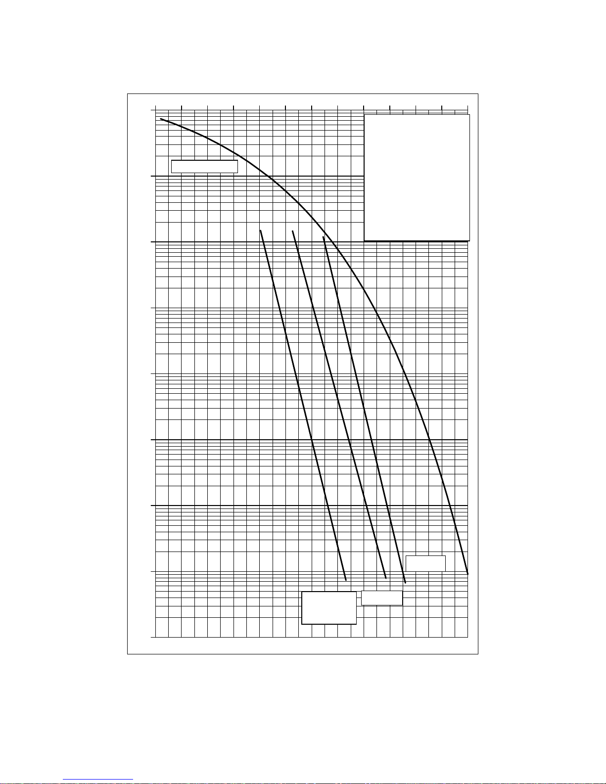
1E-9
1E-8
1E-7
1E-6
1E-5
1E-4
1E-3
1E-2
1E-1
1 2 3 4 5 6 7 8 9 10 11 12
E
b/No in d
B
Test Conditions:
FEC: Viterbi
Rate: 128 kbps QPSK
TX: 140.0000 MHz
RX: 140.0000 MHz
V.35 Scrambling
Input Level: -60 dBm
Spec limit
R1/2 Coding
Ideal BPSK/QPS
K
Rate 3/4
Rate 7/8
P300H P300 Series Modem Installation and Operating Handbook Page 34
P300 Modem Series , Error Probability versus Eb/No - Viterbi Decoding
Page 35
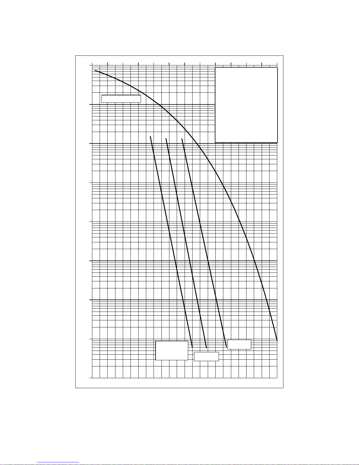
1E-9
1E-8
1E-7
1E-6
1E-5
1E-4
1E-3
1E-2
1E-1
1 2 3 4 5 6 7 8 9 10 11 12
E
b/No in d
B
Test Conditions:
FEC: Sequential
Rate: 64 kbps QPSK
TX: 140.0000 MHz
RX: 140.0000 MHz
V.35 Scrambling
Input Level: -40 dBm
Spec limit
R1/2 Coding
Ideal BPSK/QPS
K
Rate 3/4
Rate 7/8
P300H P300 Series Modem Installation and Operating Handbook Page 35
P300 Modem Series , Error Probability versus E b / No - S equential Decoding at 64kbps
Page 36
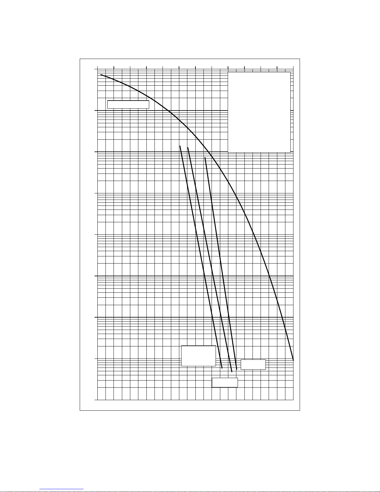
1E-9
1E-8
1E-7
1E-6
1E-5
1E-4
1E-3
1E-2
1E-1
1 2 3 4 5 6 7 8 9 10 11 12
E
b/No in d
B
Spec limit
R1/2 Coding
Ideal BPSK/QPS
K
Rate 3/4
Rate 7/8
Test Conditions:
FEC: Sequential
Rate: 2048kbps QPSK
TX: 140.0000 MHz
RX: 140.0000 MHz
V.35 Scrambling
Input Level: -50 dBm
P300H P300 Series Modem Installation and Operating Handbook Page 36
P300 Modem Series , Error Probability versus E b/No - Sequential Decoding at 2048kbps
Page 37
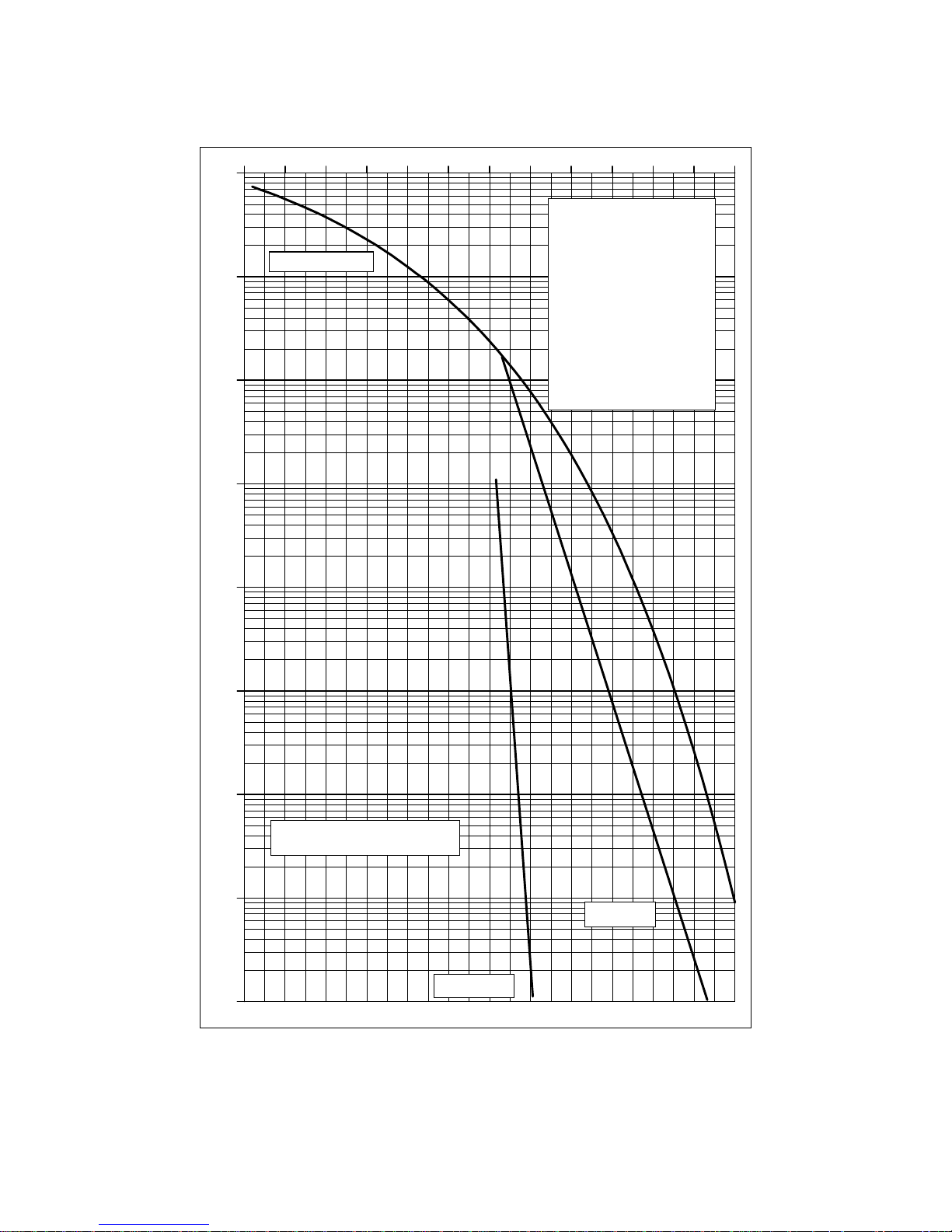
1E-9
1E-8
1E-7
1E-6
1E-5
1E-4
1E-3
1E-2
1E-1
1 2 3 4 5 6 7 8 9 10 11 1
2
E
b/No in d
B
Test Conditions:
FEC: Rate 2/3 Pragmatic TCM
Rate: 2048 kbps 8PSK
TX: 70.0000 MHz
RX: 70.0000 MHz
V.35 Scrambling
Input Level: -45 dBm
Ideal BPSK/QPS
K
TCM plus RS
TCM no RS
R
S = Concatenated Reed-Solomo
n
Outer Coding (219,201)
P300H P300 Series Modem Installation and Operating Handbook Page 37
P300 Modem Series , Error Probability versus Eb/No - 8PSK/TCM with/without Reed-Solomon
Page 38
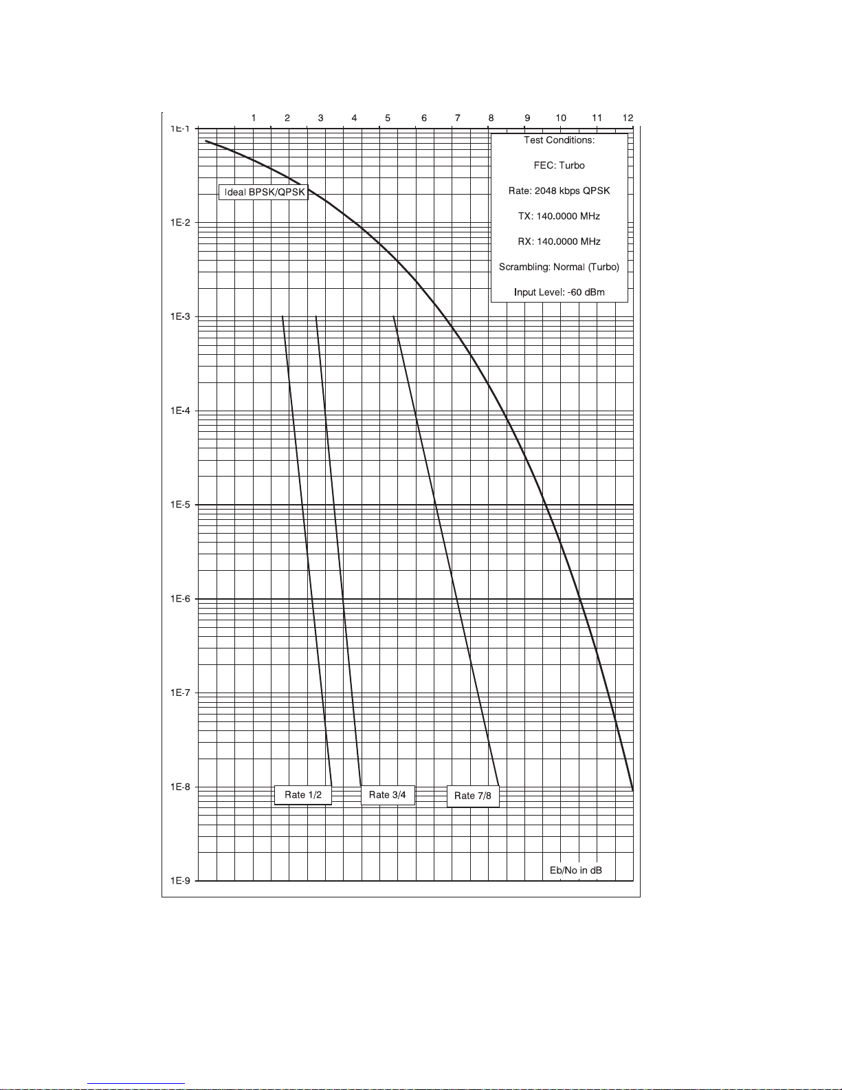
P300H P300 Series Modem Installation and Operating Handbook Page 38
P300 Modem Series , Error Probability versus Eb/No - Turbo Codec
Page 39

P300H P300 Series Modem Installation and Operating Handbook Page 39
5 INSTALLATION AND CO NF IG URAT IO N
5.1 UNPACKING
Prior to unpacking, inspect the exterior of the shipping cont ainer for evidence of damage during transit. If
dam age is evident, contact the Carrier im mediately and submit a damage report. Carefully unpack all
items, taking care not to discard packing materials, particularly the moulded foam inserts. Should the unit
need to be returned to Paradise Datacom, USE THE ORIGINAL PACKING CARTON. This is the only
approved shipping container that Paradise recognises.
5.2 VISUAL INSPECTION OF EQUIPMENT
Once unpacked, v isually inspect the unit for damage. The shipping carton in w hich the Modem is shipped
has been used by Paradise to ship our products worldwide for a number of years. It has shown, through
experience, that it can withstand very rough handling. Therefore, if the equipment received is damaged,
there can be no doubt that i t has been subjected t o abnormal or abusiv e treatment - please file a claim with
the Carrier im mediately and then contact Paradise Datacom. Assuming, however, that the equi pment has
been received in perfect condition, proceed w ith the ins t allation of the equipment.
5.3 INTERFACE OPTIONS
Unl ike previous Paradise products this unit is fitted as standard with an interface that is AN INTEG RAL
PART OF THE MODEM main board, DO N OT TR Y TO R E M O V E THE CARD. Customer specific interface
options are available, but these requi re t he st andard int erface to be `snapped off` and a connector soldered
to the board before the modem can accept other standard Paradise interface cards.
Note if fitting t he additional G.703 options (T1 or E1) that there are links and switches on the card, and
these should be set B EFORE the card is installed.
5.4 IF INTERFACE
Connect the appropriate cables t o the Transmit IF and Receive IF connectors at the rear of the unit. Output
power level can be controlled using the front-panel menus. The optimum input level for the demodulator
is -45dBm ±15dB.
5.5 POWER UP
At power up the unit performs an ini tialisation procedure, which lasts approximately 3 seconds. If t he unit
was prev i ously operati onal, i t wi ll enter operating mode. If the unit was previously non-operational, then t he
main menu will be displayed. Duri ng t he power-up phas e, t he uni t w i ll display the product number P300 with
a V & S suffix in dicating the presence of the Viterbi and / or Sequential codec, plus the unit serial number.
The user should then select SETUP, INITIAL CONFIG, (to define every parameter prior to operation), later
changes to the configuration are made with the CHANGE option. The Status screen cannot be s elected
unless SETUP, INITIAL CONFIG has been performed.
Page 40

P300H P300 Series Modem Installation and Operating Handbook Page 40
1:Status 2:Change 3:Monitor 4:Info
5:Log 6:Test 7:Setup 8:Action 9:Help
Main Menu
6 MENU SYSTEM
6.1 INTRODUCTION
All configuration & monitoring features are accessed from the front panel vi a the menu system. Provided
an operator has an understanding of how the menu system works, there is no need to try and memorise
the menu structure itself, as selecting a single option (SETUP, INITIAL-CONFIG, explained later) will make
the unit p r ompt for all needed configuration parameters. The structure of the menu system is however
shown on the next few pages for reference.
<<<
THE 1 MINUTE GUIDE TO FRONT PANEL OPERATION
===
The main menu c an be acc essed from any display with the MAIN key. It is from this main menu that all
functions are selected.
Whenever the '
8
' or `9' symbol appears it indicates that further information is available by press ing the UP
or DOWN key. This information is usually worth looking at (otherw ise we wouldn’t have put it there !).
The NO key functions as a backst ep/backspace key , both w hen enteri ng numeric data, and when traversing
the menus. The YES key doubles as an enter key for numeric entri es. Where a numeric entry requires many
digit s (eg I F frequency), press i ng YES after enteri ng all significant digits fills the rest of the entry with zeroes ,
pressing YES again, enters this value.
Wh en the user is requested to select a configuration parameter, the last setting is always displayed in
[square brackets]. To select the same option again, just press the YES Key (ie you don’t have to reselect
the same option to get past the menu, just press YES)
Options displayed with a colon eg "1:Status" switch to another screen or subsequent m enu but do not
aff e ct operation. Options displayed with a equals sign eg "1=Off" change the configuration and may (if
changing a relevant parameter) affect the traffi c. Reselecting a current option (or pres sing YES to select
the current opti on) will never cause a traffic i nterruption.
When a unit is shipped (or if the non-volatile memory is cleared) it will have an blank configuration and
require the operator to use SETUP, INITIAL-CONFIG pri or to allowing STATUS to be selected. This prompts
for all parameters required for a complete configuration.
Wherever possible m enus state “(normal)” after the most com mon option. If in doubt, select the normal
option i f t here is one, it works every t ime !
After SETUP, INITIAL CONFIG has been performed once, minor changes to the configuration may be made
with the CHANGE opti on f ro m t he main menu. CHANGE allows parameters such as Tx & Rx service/dat a
rates, clocking, IF frequenci es, and miscellaneous parameters to be set wi t hout going through the entire
SETUP process. If however y ou make a major change to the service (such as switching from Closed Net to
IBS) y ou might decide a qui ck run through SETUP, INITIAL CONFIG again (accepting the current values with
the YES key) wi ll h ighlight an y new p a ra met e r s ( w ith sen s ible defa u lt s ) that are relevant to this major change
of service.
Make use o f the Rx=Tx option, it’s great, it cuts down configurat ion errors, and generally makes life easy .
At least read the not e on Rx=Tx in section 6.7 on page 86 so you know what you are missing !
Page 41

1:Status 2:Change 3:Monitor
4:Info 5:Log 6:Test 7:Setup 8:Action
1:Status 2:Change 3:Monitor
4:Info 5:Log 6:Test 7:Setup 8:Action
1:Status 2:Change 3:Monitor
4:Info 5:Log 6:Test 7:Setup 8:Action
Change: 1:Tx 2:Rx 3:Terr-Intfc
4:Rem M&C 5:User-Opt 6:Time/Date
Tx: 1:Service 2:Baseband 3:Clocking
4:Modulator 5:ESC/Aux
1:Initial config 2:Config check
Memories: 3:Store 4:Recall 5:Erase
Tx Service: [?]
1=Off 2=Closed Network 3=IBS/SMS
Tx Clock Mode: [Internal]
1=Tx clock in 2=Internal 3=Rx clock
Set Tx terrestrial rate: [0000000bps]
(2400-4920000) ??????? (YES)
Tx path OK for 3.7days
Rx path OK for 2.1days BER < 1E-12
1
1
1
2
3
7
MAIN
MAIN
MAIN
Main Menu
Main Menu
Main Menu
2:Change
1:Status
1:Tx
3:Clocking
Current value displayed in [square brackets].
Press 1, 2 or 3 as required, YES to leave unchanged,
NO/PREV to go back one menu, or MAIN for main men
uNO/PREV to go back one menu, or MAIN for main menu
7:Setup
1:Initial config
TO COMPLETELY SETUP INITIALLY
T
O CHANGE PARMETERS (eg Tx CLOCKING)
T
O DISPLAY STATUS
Modem prompts for
every parameter in turn.
Operator continues to enter selection
until modem completely configured !
0
1 2
3
4
5 6
7
9
8
YES /
ENTER
NO /
PREV
MAIN
Full Keyboard Detail
P300H P300 Series Modem Installation and Operating Handbook Page 41
When the configuration is complete, select STATUS from the main menu, check the LED status indicators,
and read the message on the LCD. The messages are carefully worded to convey as much information
as possible about any faults.
If you have configured the unit, but it will not operate as expected, try SETUP, CHECK, this takes
approximately 10 seconds to run and checks the configuration for unusual settings (eg IBS with 7/8 rate
FEC). If anything is found a warning is displayed and can be masked by pressing YES. These are only
warnings, and after y ou mask each dis play ed warni ng y ou may continue to operate in that mode if required.
Use the INFO, VIEW CONFIG, TX/RX/COMMON screens to display the summarised configuration.
Then, if need be, read the rest of thi s handbook. I f that fai ls, when you are sure you have the unit configured
correctly and you have checked the status on the LCD, call us for technical support. We will do our best
to remotely diagnose t he problem.
6.2 MENU S TRUCTURE DIAGRAMS
The full modem menu structure is presented on the following pages. In order to not over-complicate the
menu screens for modems which do not have the full feature set, some m enu options only display if
features are fitt ed and/or active.
Items in [Square Braces] are relevant only when the modem is configured in certain modes and are not
display ed unless the modem is suitably configured. For example menu options relating t o cert ain features
of IBS or IDR framing only display if the Tx or Rx Service i s set for IBS or IDR.
Items dis played w i th a “-Option” suffix such as [AGC OUTPUT]-Option:Monitor/AGC only appear on t he
menu's when the relevant feature is available on that modem. This may be a feature controlled by a front
panel entered “Feature Code” or a feature requiring a hardware option (as per this example).
Some items require not only the feature to be available in the modem, but also the feature to be currently
activ e before they are di s played. For example the option to raise a deferred alarm if the distant Eb/No falls
below a certain level (shown on the diagrams as [DISTANT Eb/No]-Option:AUPC) requires the AUPC
feature to be available and
switched on before the menu option is shown.
Page 42
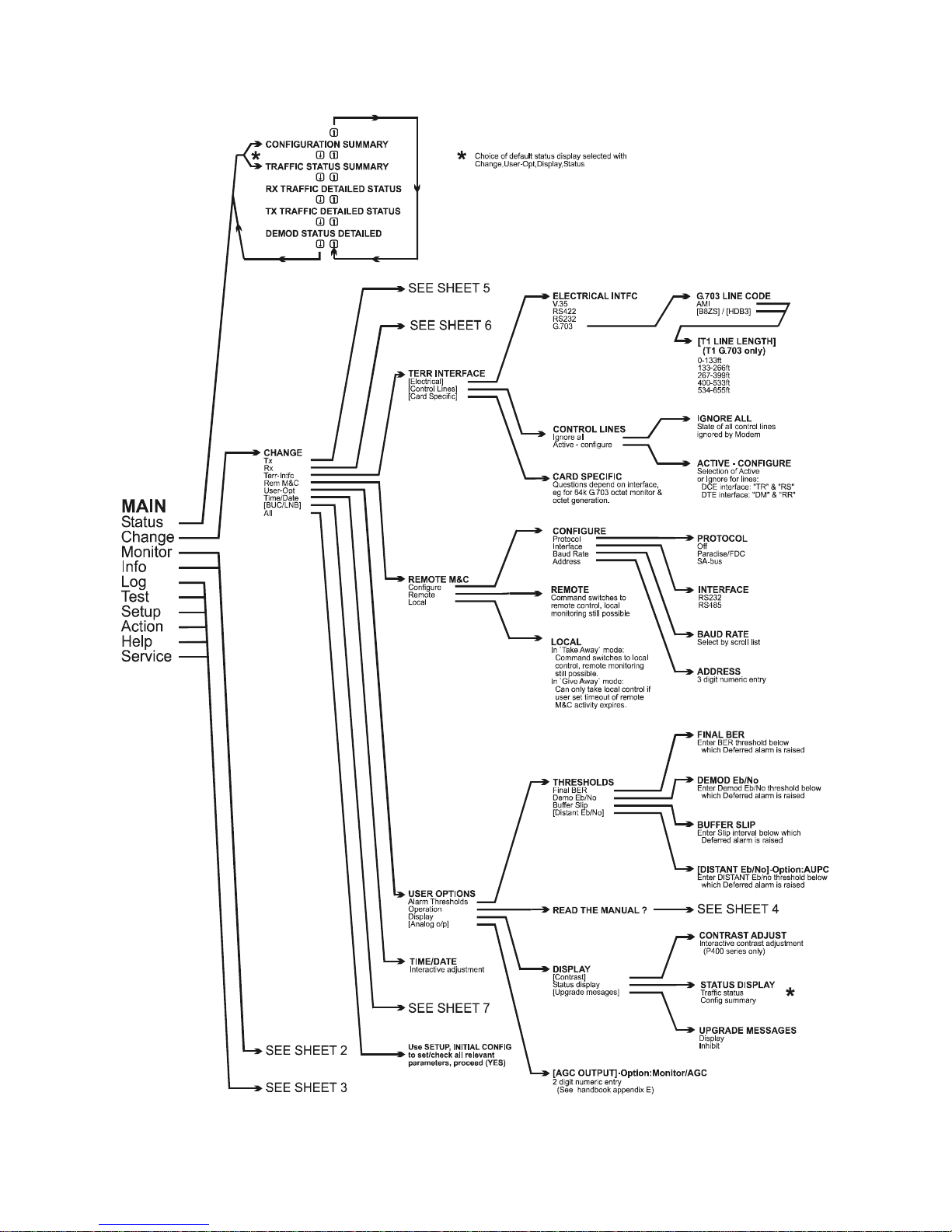
P300H P300 Series Modem Installation and Operating Handbook Page 42
6.2.1 Menu Structure Sheet 1 / 7 (Main: Status, Change)
Page 43
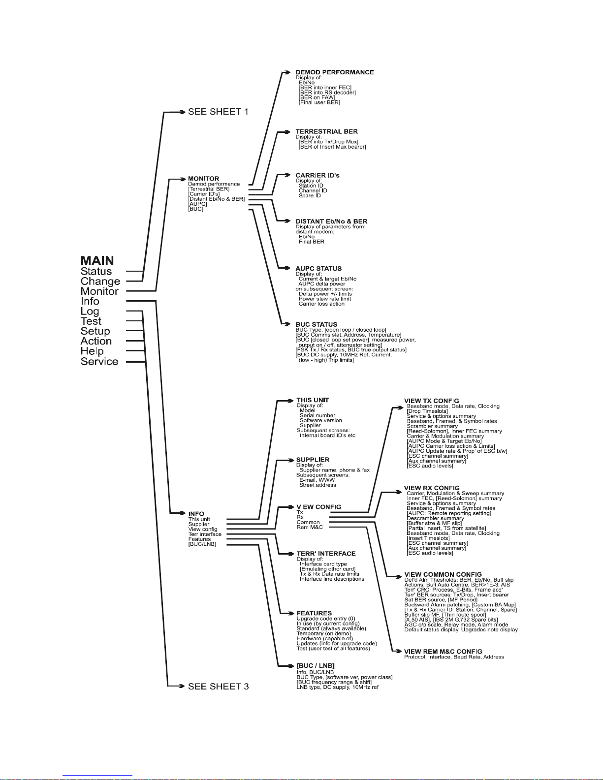
P300H P300 Series Modem Installation and Operating Handbook Page 43
6.2.2 Full Menu Structure S heet 2 / 7 (Main: Mon itor, Info)
Page 44
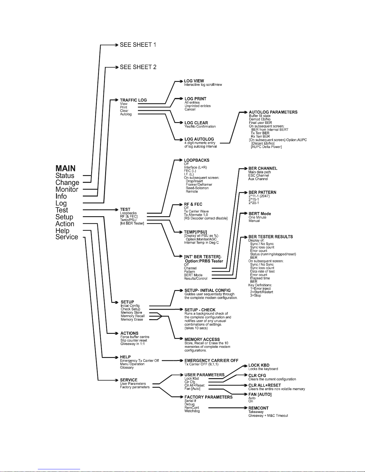
P300H P300 Series Modem Installation and Operating Handbook Page 44
6.2.3 Full Menu Structure Sheet 3 / 7 (Main: Log, Test, Setup, Action, Help)
Page 45
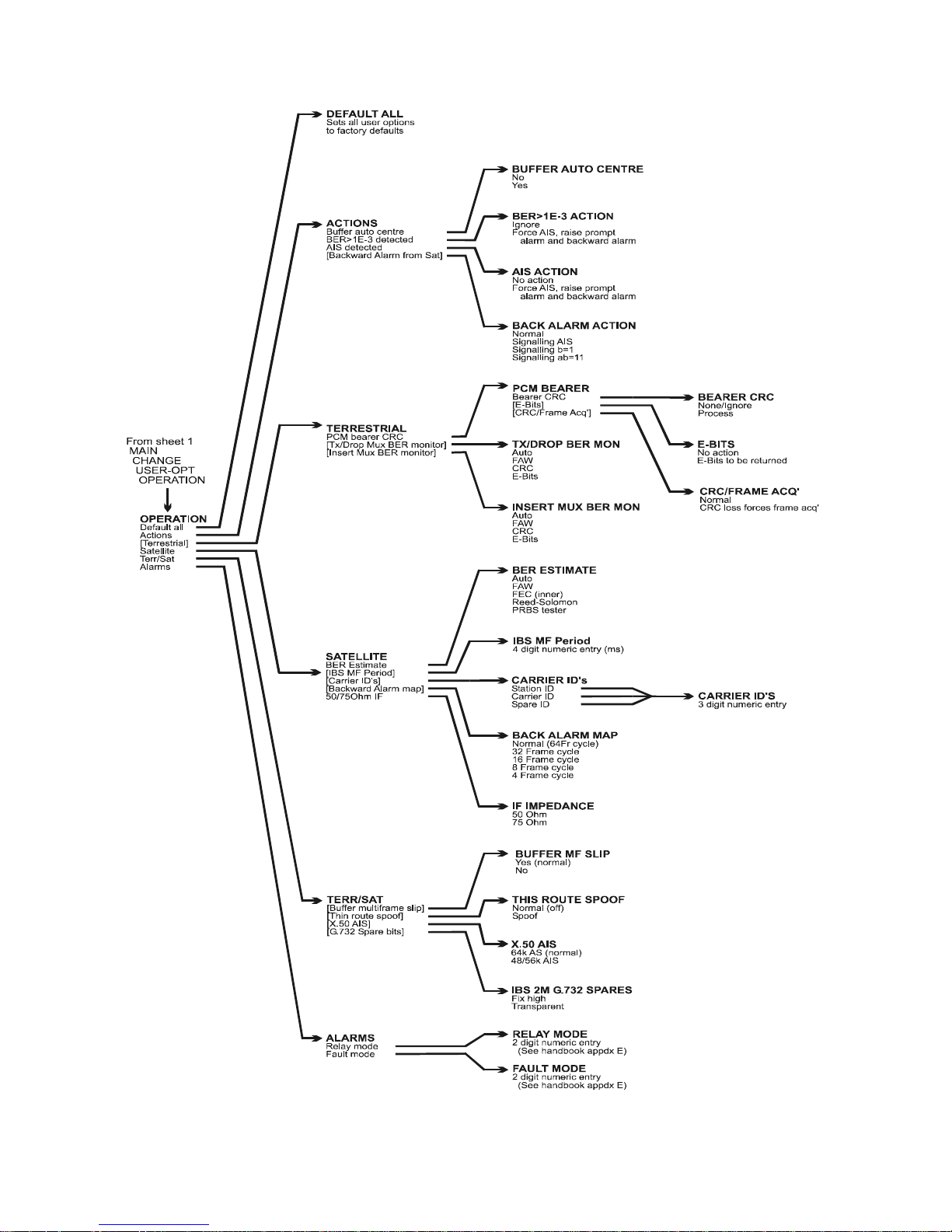
P300H P300 Series Modem Installation and Operating Handbook Page 45
6.2.4 Full Menu Structure Sh eet 4 / 7 (Main, Change, User-Op t, Op erati o n )
Page 46
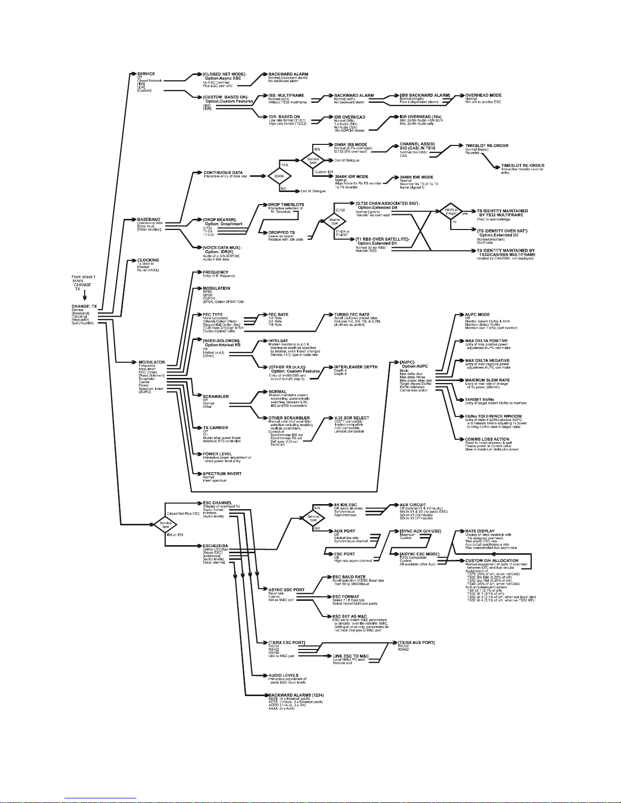
P300H P300 Series Modem Installation and Operating Handbook Page 46
6.2.5 Full Menu Structure S heet 5 / 7 (Change, Tx)
Page 47
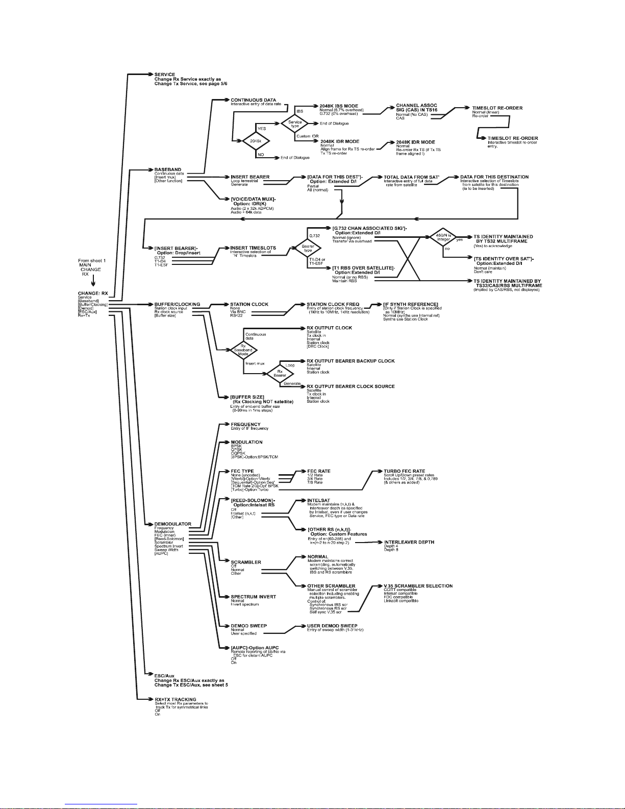
P300H P300 Series Modem Installation and Operating Handbook Page 47
6.2.6 Full Menu Structure S h eet 6 / 6 (Ch an ge, Rx)
Page 48
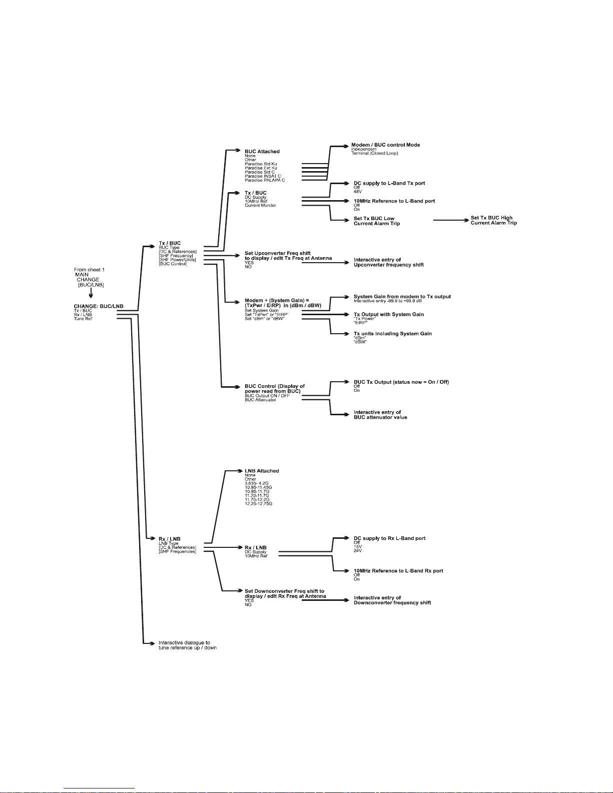
P300H P300 Series Modem Installation and Operating Handbook Page 48
6.2.7 Full Menu Stru ctu re Sheet 7 / 7 (Change, BUC/L NB)
Page 49
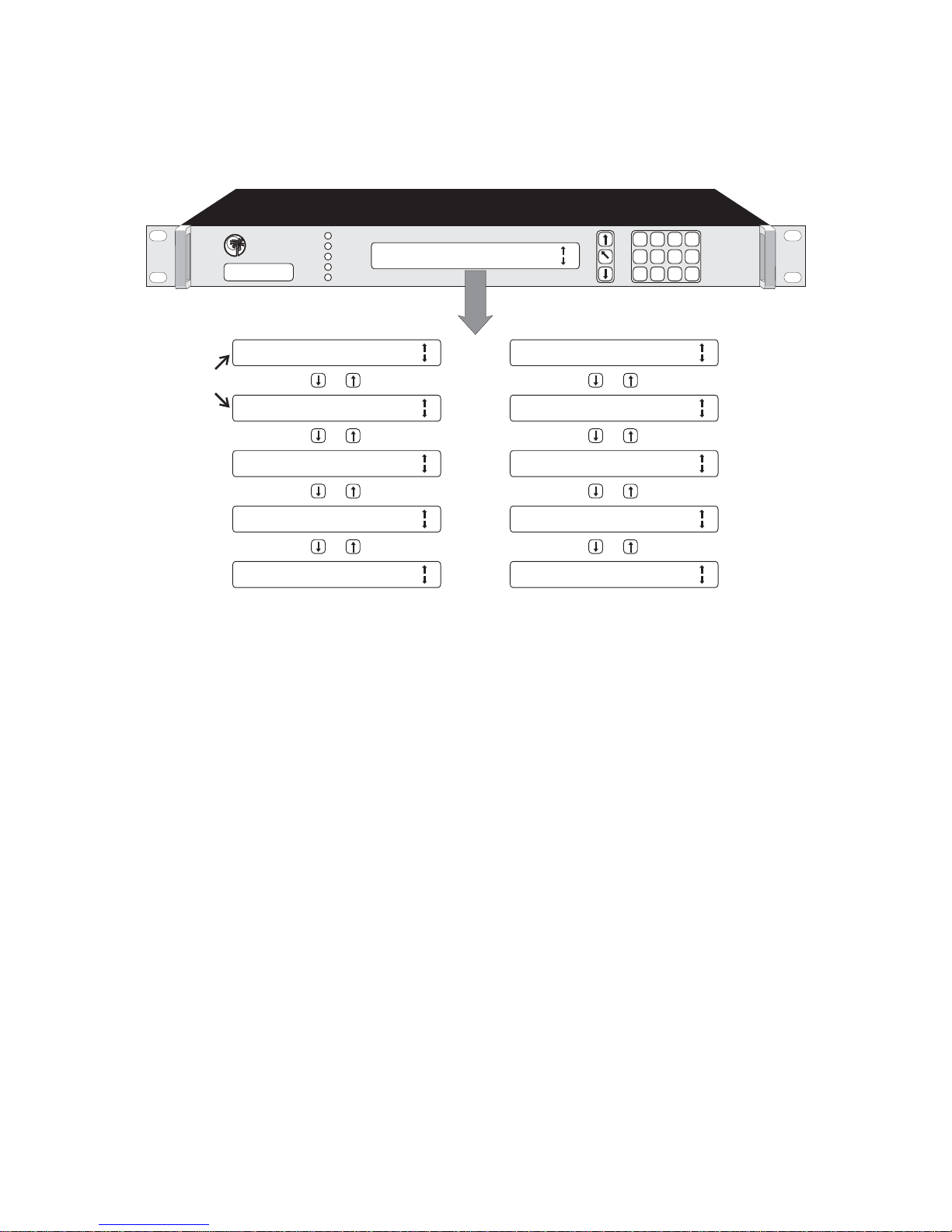
Tx: 68.5734M 64k Rx: 73.4256M 64k
Carr:On, Eb/No:16.3dB Local
Tx: 68.5734M 64k Rx: 73.4256M 64k
Carr:On, Eb/No:Unlocked ALARM!
Tx path OK for 3.7days
Rx path OK for 2.1days BER < 1E12
Tx Fault: No clock from interface
Rx Fault: Demod unlocked at 73.4256MHz
Rx path OK since: 15:13:44 on 05/07/97
User BER: 1.0e-12, Buffer +00 -00 53%
Rx Fault: Demod unlocked at
73.4256MHz with sweep width of 10KHz
Tx path OK since 17:10:25 on 05/07/97 Tx Fault: No input clock from
interface (line TT)
Demod: Eb/No:16.3dB User BER:1.0e-12
Offset: +3.4KHz Carrier Level: -38dBm
Demod: Unlocked
STATUS
RX OK
TX OK
TEST
STANDBY
DATACOM
PAR AD ISE
Tx path OK for 3.7days
Rx path OK for 2.1days BER < 1E-12
0
1 2
3
4
5 6
7
9
8
YES /
ENTER
NO /
PREV
MAIN
P300 Series
Satellite Modem
Status Display (no faults)
Status Display (Tx & Rx faults)
Configuration
Summary
Traffic Status
Summary
Rx Status
(detailed)
Tx Status
(detailed)
Demod status
(detailed)
U
ser selection of
User selection of
d
efault screen when
default screen when
‘
Status‘ selected
‘Status‘ selected
O
ther status screens
Other status screens
b
y pressing Up or Down
by pressing Up or Down
f
rom 1st ‘Status‘ screen
from 1st ‘Status‘ screen
P300H P300 Series Modem Installation and Operating Handbook Page 49
6.3 Status SCREEN DISPLAY
When Statu s is selected the LCD switches to a display of the current modem status. This is a series of
screens which are accessible from each other with the Up and Down keys. The available stat us screens
are summarised in the following diagram:
The operator has the option to display either the Configuration Summary Screen (shown firs t above) or
the Traffic Status Sum mary S creen (show n second above) when Status is selected from the main menu.
The selection between s creens i s made under Change, User-Opt, Display. These screens are now each
discuss ed in turn:
Page 50

P300H P300 Series Modem Installation and Operating Handbook Page 50
Tx:70.0000MHz 2048k Rx:70.0000M Hz 2048k
CARR:No r mal Eb/No>15.0d B L O CAL Info
9
Configuration Summary Screen
CONFIGURATION SUMMARY
This screen displays a summary of the configuration on the top line. The lower line provides carrier unit
and traffic messages such as "Carr:On", "Unit Fault" or "Traffic Warn", and the operator has to press the
Down ke y to dis play the Tx & Rx Traffic Summary screen i n order to determine what the fault is . The fields
can take the following values:
Carrier Stat us: CARR: No r mal Normal Tx st atus
CA RR: DISABLED Carrier state set to `Off` (formerly CARR:Mute-Off)
CA RR: Mute-Brk Carrier set to `Power Break Mute`, requires
operator to confirm if carrier can be
retransmitted as power outage has occurred.
CARR: Mute-1:1 Muted by 1 for 1 logic
CARR: Mute-Ext Muted by external signal on alarms connector
CARR: Mute-RTS Carrier set to RTS controlled, and interface RTS
line is off
CA RR: Mute-Flt M uted, due to an i nt ernal fault (eg synthesiser lock)
CA RR: F AULT !! There is a fault in the carrier on/off logic,
disconnect the carrier from the satellite.
Demod status: Not Locked If the demodulator is unlocked
Eb/No=xx.xdB
9
When the demodulator is locked a valid Eb/No is
displayed
Pressi ng the down arrow leads to further i nformation
Unit St atus (in order of priority):
Unit Fault There is a Unit Fault
Cfg-Error The Uni t cannot perform as requested
Unit-Warn There is a Unit Warning
Cfg-Warn There is a configuration warning (from Setup,
Check)
Cfg-Info There is a Config Info message (from Setup,
Check)
Traf-Fault A Traffic Fault exists
Traf-Warn A Traffic Warning exists
Remote Rem ote M&C mode, no warnings or test modes
active.
Local Local mode, no warnings or test modes active.
Page 51
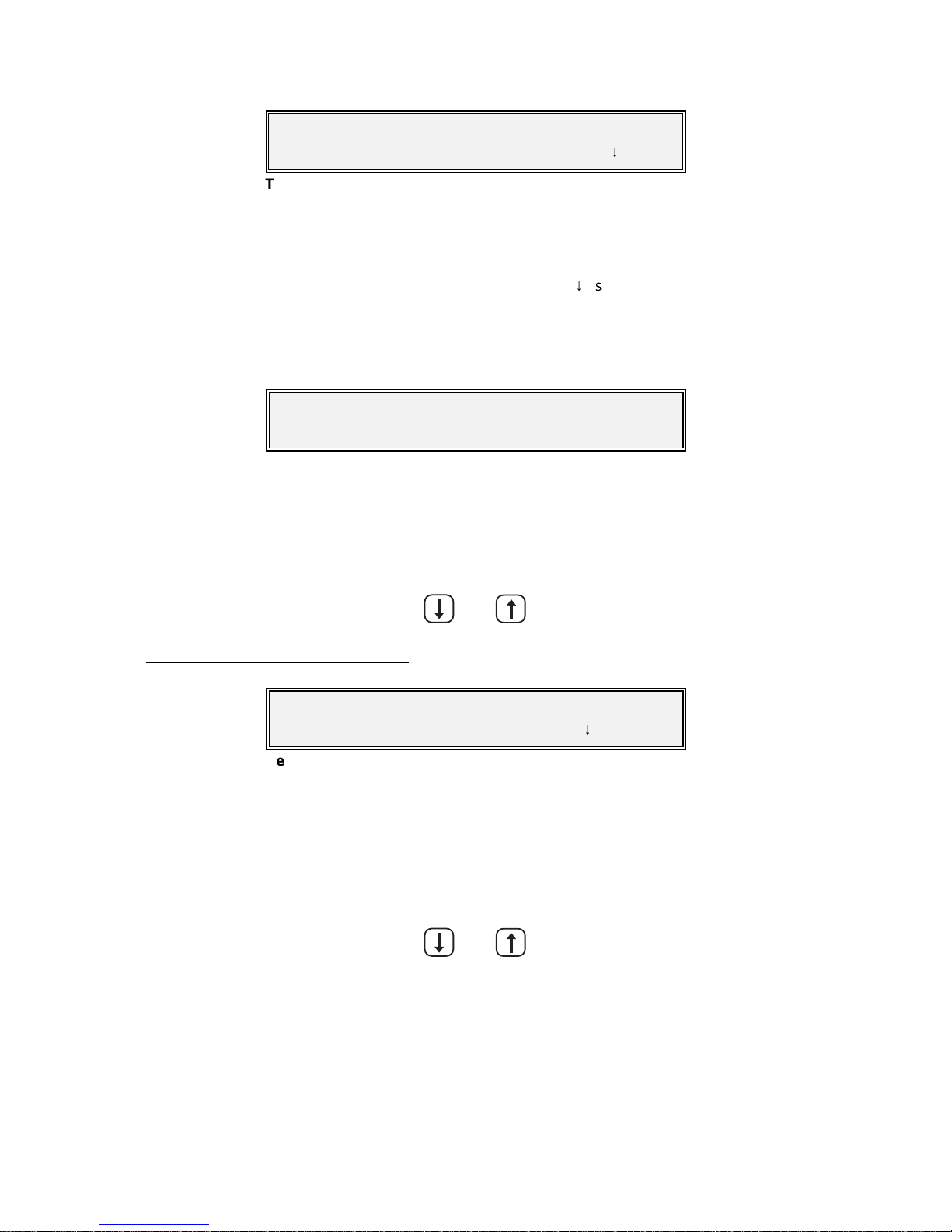
P300H P300 Series Modem Installation and Operating Handbook Page 51
Tx Fault: Data input is all ones (AIS)
Rx path OK for 36.8 hrs, BER <1 E12 Info
9
Traffic Summary Screen (Tx top line, Rx bottom line)
Unit Fault: Tx IF synth failure,
Tx carrier muted.
Unit Fault (overrides Traffic or Configurat ion Summary screens)
Rx OK since 22:58 on 3/6/97
BER >1E-7* Buffer +2 -0 53% Tx
9
Detailed Receive Traffic S tatus
TRAFF IC SUMMARY SCREEN
When there are no faults t his screen shows how long since the last i nt erruption for both paths (as for t he
lowe r line o f the example shown), together with the carrier status for the transmit path and the Eb/No
(disc ussed later) for the receive path. If either path has a traffic fault / warning active, then the status is
replac ed by an abbreviated 40 character fault message on the top or the bottom line for Tx & Rx
resp ectively. A more descriptive message is available on the “Info
9
” screens accessed with the Down
Arr ow key. These display a more descripti ve 80 character messages for the Detailed Rx Traffi c status ,
the Detailed Tx Traffic Statu s, and a Detailed Demodulator Status.
Any Unit Faults override Tx & Rx Traffic S u mmary and display s the fault message, such as
When a unit fault is displayed, it takes over the whole of the Tx & Rx Traffic Summary screen (as it is
important, and likely to relate to bot h Tx & Rx paths). The three detailed screens are however sti ll av ailable
by pressing the Down key from the Unit Fault Message. On each successive press the screen cycles
through the following three screens, until on the fourth press it returns to whichever of the two Status
Screens has been selected as t he default.
DETA ILED RECEIVE TRAFFIC STATUS
This screen normally shows t he ti me of the last traffic interruption, the (estimated) user BER, along with the
Doppler buffer overflow & underflow counts (reset by ACTION, RESET SLIP COUNTS), and the current buffer
fil l status. If the BER indicati on is followed by an asterisk, then there have been less than 100 errors, and
the results are statistically weak. If there is a receive traffic fault, then a more detailed two line description
of t h e f a ult/warning replaces the status information (as opposed to the one line message on the Status
Traffic Summary Screen). P ressing down agai n selects the Transmit Detailed Traffic Stat us .
Page 52
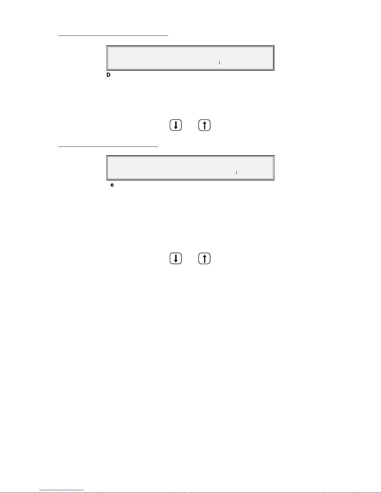
P300H P300 Series Modem Installation and Operating Handbook Page 52
Tx OK since 08:25 4/6/97
Carr:Normal Dem o d
9
Detailed Transmit Traffi c S tatu s
Demod Stat: Eb/No: 8.5dB User BER: 4E-3
Offset: 18kHz, Level: -48dBm S tat
9
Detailed Demodulator Status
DETAILED TR ANSMIT TRAFFIC STATU S
As wi th t he Rx screen, this shows the dat e of the last i nterrupt ion to the Transmit path, replaced with a more
detailed t wo line descri ption o f any tr affic faul t/warning condition i f it exists. Pres sing down again s elects the
Demodulator Detailed Status.
DETA ILED DEMODULATOR STATUS
This screen show s t he est i mated Eb/No. This i s the co mpo s ite Eb/No including framing overheads (as used
by INT E LSAT when specifying m odem performanc e figures). The BER is the final USER B ER which is
being pa ssed to the customer. The Offset is the measured error of the received carrier, relative to the
nom inal position expected which is useful for determining the frequency drift due to the satellite and
frequency conversion equipment. The Level is the level of the desired carrier estimated by the
demodulator and is only shown i f the Monitor/AGC option is fitted. From this screen the Down Arrow leads
back to the selected Status screen.
(Back to the selected Status S creen , `Co n fi g Summary` or `Tx & Rx Traffic Summ ary`)
Page 53

P300H P300 Series Modem Installation and Operating Handbook Page 53
Setup: 1:Initial Config 2:Check
Memori es: 3:S tor e 4:Recal l 5:Erase
Setup Menu
Change: 1:Tx 2:Rx 3:Terr-Intfc
4:Rem M&C 5:User-Op t 6:Time/Date 7:BUC/LNB
Change Menu (local contr ol)
Change lim ited as Remote M&C active !
Change: 1:Rem M&C 2:Time/Date
Change Menu (remote M&C)
6.4 SETUP - INITIAL CONFIGURATION MENU
When delivered, or if the non-volatile memory should ever be cleared, the unit must be compl etely
configured using t he S ETUP, I N I T I A L C O N FIG option. This takes the operator t hrough all the sect ions of the
CHANGE procedure described below to ensure all parameters are set. Only when 'SETUP, INITIAL-CONFIG'
has been performed once can STATUS be selected from the m ain menu. This ensures operation is not
selected until all criti cal parameters are speci fied.
Other options on the SETUP menu are:
CHECK: Which allow the setup to be checked, and looks for unusual combinations of
configuration parameters (eg IBS with rate
f
FEC coding, multiple scram bl ers
sel ected). Check does not prevent operation w ith any configurat ion, it is simply a
convenience for the operator if there are configuration difficulties. The Setup
Check takes several seconds to run and displays a message when the process
is complete.
MEMORIES: ST OR E , RE C A L L, and ERASE which allows access to the configuration memories
of the Modem. The current configuration can be stored, anot her recalled, or an
old stored configuration deleted. This provides a fast method of switching
between multiple configurati ons when required.
6.5 CHANGE MENU
It is under the Change menu that individual parameters may be varied after an initial SETUP, INITIALCONFIG h as been perform ed. If the unit is operating under Remote M&C, the options on the change
screen are limited to only the remote M&C configuration & the time/date:
Normal Change Screen (local control):
(Option 7: B UC/LNB only on P310 L-Band modems).
Change Screen (Remote M&C):
Each of these opti ons will be described in t he followi ng sections:
Page 54

P300H P300 Series Modem Installation and Operating Handbook Page 54
Tx: 1:Service 2:Baseband
3:Clocking 4:Modulator 5:ESC/Aux/BA
Change, Tx Menu
Tx Service: [IDR] 1=Off 2=Cl o sed Network
3=IBS/SMS 4=IDR 5:Cu sto m
Change, Tx/ Rx, Service Menu
6.6 CHANGE, TX MENU
The Change, Tx menu is shown below. Note that options 2-5 are only displayed when the SERVICE option
is set to something other than `Off`, and so initially, the screen may only show the SERVICE option.
Taking each of these possible selections in turn:
6.6.1 Change, Tx/Rx, SERVICE Menu
The options are:
OFF This disables the path completely for Tx or Rx only operation. All alarms for that
path are muted, and traffic faults ignored. For the Tx path the Tx carrier is also
muted.
CLOSED NET The Tx /Rx pat h operates in a `Closed Network` mode. I f the Async ESC feature
is av ai lable (standard P300-IBS and above) then a subsequent screen (described
in the next s ection) asks if i t is normal Closed Network, or whether Closed Net
Plus ESC is required. Normal Clos e d Network adds no overhead to the data and
is compatible with other closed netw ork equipment such as the Paradise P 200,
and closed network equipment from other vendors.
Closed Net Plus ESC adds the lowest possi ble overhead to the satellite dat a t o
provide whatever ESC rate is selected. When this mode is selected there is also
the option t o prov i de a Backw ard Alarm facility . Closed Net Plus ESC also has the
advantage that at rat es above 32kbps a synchronous scrambler is used (in place
of t he e r ro r mult iplyi n g V . 3 5 scrambler u s e d on normal closed network links) and,
if u sed with Drop/Insert, the `Timeslot Identity is maintained`. If you want the
backward alarm, synchronous scrambler, or Timeslot ID Maintenance
advantages of Cl osed Net Plus ESC, but don’t want an ESC channel, simply
select the ESC to the lowest Baud rate available (50 Baud), and the rest of the
features wi ll be prov ided within less than 0.5% overhead.
IBS/SMS The Tx/Rx path operates in IBS/SMS `Open Network` mode, where a 1/15th
framing overhead is added t o the dat a. I n t hi s mode the Modem is compatible with
other `Open network` equi pment such as the P 230, P 230D/ I, OEM modems used
with a P1300 framing unit, or other `Open Network` equipment from other
vendors. Refer to the s ecti on "IBS/SMS Service Features" in Appendix F on page
207 for a full description of IBS/SMS features.
IDR The T x path operates in IDR mode, where a 96kbps framing overhead is added
to the data. In this mode the equipment is com patible with OEM modems used
with a P 1300 framing unit , or other `IDR` equipment from other vendors. Refer to
section "IDR Service Features" in Appendix F on page 213 for a full description
of IDR features.
Page 55

P300H P300 Series Modem Installation and Operating Handbook Page 55
Closed Network mode [?]:
1=No ESC (normal) 2: Plus ESC (min o/h)
9
Change, Tx/ Rx, Service, Clos ed Net , ESC Menu
Custom This allows the operator to select a framing format based on the standard
IBS/SMS or IDR definitions, but with non-standard or extra features such as
Minimum overhead framing, or Multidestinational IBS. A description of the
features and menus which follow this choice are in section 7.1.1 "Change, Tx/Rx,
Service, Custom Menu" on page 133.
6.6.2 Change, Tx/Rx, Service, CLOSED NE TWORK
These screens are only show n i f the A sy nc E SC feature is available, standard on the P300-IBS and abov e.
Note: Closed Net Plus E SC is ava ilable with the P400 s eries modems, refer to “Closed Network Plus ESC
vi a t he Custom Service menu” in section 8.7.2 on page 148.
When Closed Net is selected the following screen is shown to allow the selection of normal Closed
Network operation, or Closed Net Plus ESC:
NO ESC The modem operates without adding any overhead to the data, this is `normal`
Clos ed Net work mode. Normal Closed Network adds no overhead to the data
and is compatible with other closed network equipment such as the Paradise
P200, and closed network equipment from other vendors.
PLUS ESC The modem adds the minimum possible ov erhead t o the satellite data (down to
<1%) to support t he asy nc ESC rate you set. The exact overhead used can be
viewed on the Info, View Config, Tx/Rx screens. It provides the following
facilities:
'
A variable rate ESC channel (up to approx 70% of main channel rate)
'
An optional backward alarm facility.
'
At rates of 32kbps and above it provides a synchronous scrambler to
replace the error multiplying V. 35 normally used on closed network links.
'
If used with Drop/Insert (Yes, Closed Network with Drop/Insert), it
provi des Timeslot ID maintenance across the link.
See the first few paragraphs of Appendix F where Backward Alarms,
Synchronous Scrambling, and Timeslot ID Maintenance are discussed (in
relation to an IBS/SMS carrier).
Note: As t he ov erhead affects t he final composite framed data rate, and the ESC
& backward alarm settings determine the required overhead, then for two
modems to interwork the following parameters must match on both pieces of
equipment:
i
Main data rate.
i
Asy nc E S C B aud Rate, Character length and Parity.
i
Backward Alarm option (ie bot h enabled or both disabled).
i
Baseband modes (ie both Cont inuous Data or both Drop/Insert).
Page 56

P300H P300 Series Modem Installation and Operating Handbook Page 56
Backward Alarm facility:[?]
1=Normal (Back' Alm) 2=No Backward Alarm
Change, Tx/ Rx, Service, Closed Net, Plus ESC, BA Menu
If No ESC is chosen then t he di alogue ends here, otherwise it proceeds with the Backward alarm option as
follows:
NORMAL A Backward alarm facility is provided causing a deferred alarm to be raised on
this local equipment if the distant end Rx fails for any reason (eg local Tx failure,
or distant Rx failure). The proportion of the overhead assigned t o the ESC drops
slightly (68% to 65%), so the overhead may increase marginally to provide the
same async ESC rate.
NO BACK' ALM No Bac kward Alarm is sent (Tx) or received (Rx) and so slightly more of the
overhead is av ailable to the async ESC, low ering the total overhead marginally.
See "Overhead Rates" in section 8.7.1 on page 147 for details of the overhead percentage requirements
for differing mixes of main data and async E S C data rates.
Page 57

P300H P300 Series Modem Installation and Operating Handbook Page 57
Tx BB: [?] 1=Continuous data
2=Drop Mux 3=Other function
Change, Tx/ Rx, Baseband Menu
Set Tx terrestrial data rate [2048000bps]
(2400-4920K) ???????bps (YES)
Change, Tx/ Rx, Baseband, Continuous Menu
6.6.3 Change, Tx/Rx, BAS EBAND Menu
This menu allows selection of the Baseband mode of the Modem
Continuous Data Selects normal continuous data interface operation, the menu dialogue for this
continues in the next section.
Drop/Insert Mux This option is only shown if the Drop/Insert feature is avai lable, st andard on the
P300-IBS and above. It selects the Drop (Tx) / Insert (Rx) m ode of baseband
operation where a T1 or E1 P CM bearer is routed through the equipment, with Tx
data being dropped from specific timeslots of the bearer, and Rx data being
inserted back into the same or other timeslots. The menu dialogue for this
continues in section 6.6.5 on page 58.
Other Function This option is only shown if the IDR option is fitted (as this includes the
P1348/P1448 emulation mode, standard on P300-IDR and above) and the unit
is set for IBS service. It selects the two special modes of baseband operation
which u se th e Audio ports normally used for the IDR audio ESC circuit as the
main traffi c dat a. The unit can generate a 64kbps carri er compris ing just the two
32k bps A DPCM audio channels, or a 128kbps carrier comprising 64kbps data
(from the main dat a interface of the modem) plus the two 32kbps ADPCM audio
channels. These modes are effectively an emulation of the popular P1348/P1448
voice /data mu x card used often in SNG applications. The menu dialogue for this
continues in section 6.6.6 on page 62.
6.6.4 Change, Tx/Rx, Baseband, CONTINUOUS Menu
Selecting CONT IN UOUS DATA for the baseband i nterface leads to the following menu. Enter the data rat e
with any leading zeroes required, then press YES, if the field is incomplete the unit will add the trailing
zeroes (to avoid having to enter three trailing zeroes when working w ith rates such as 64000, 128000 etc).
When the field is full, pressing YES enters t he new data rate.
If the data rate is 2048000b ps and the Modem is s et for IBS/SM S service, or a Custom servi ce based on
IBS framing, then this is a special condition. In this situation there are two modes of adding IBS fram ing,
either normal (with 6.7% overhead) or G.732 mode (where the embedded framing in the G.732 is used,
and no overhead is added). These modes are often referred to in the service definition specifications as
1920kbps or 1984kbps operation . Refer to sect ion 7.2.1 "Change, Tx /Rx, Baseband, Continuous, 2048k
Menu (I B S )" on page 137 for the description of the dialogue in this case.
Similarly if the data rate is 2048000bps and the Modem is set for a Custom service based on the IDR
Low rate format the Modem can provide additional features if the data is G. 732 framed. In such a case
it can either allow the transmit timeslots to be arbitrarily re-ordered, or frame align the Tx data within the
satellite IDR frame, so that the distant receive equipment may arbitrarily re-order the timeslots. Refer to
section 7.3. 1 "Change, Tx / Rx, Baseband, Continuous, 2048k Menu (IDR)" on page 139 for the description
of the dialogue in this case.
Page 58
P300H P300 Series Modem Installation and Operating Handbook Page 58
Select bearer: [?]
1=G.732 2=T1-D4 3=T1-ESF
Change, Tx/ Rx, Baseband, Drop/I nsert, Bearer Menu
Drop TS: 1, 3-5, 17-15, 23
Toggle: ??-?? (YES)
8
Help
Change, Tx/ Rx, Baseband, Drop/Insert, Timeslot Menu
Finally for data rate of 48kbps or 56 kbps, in IBS modes the M odem automatically activates the X .50 `bit
stuff ing` to convert to/from 64kbps (as defined for IBS operation). However in Custom IBS modes the
operator is offered the opt i on of not usi ng t hi s faci lity. In Normal IBS modes then wit h 48 or 56kbps data the
satellite rate is 64kb ps x 16/15, but in custom modes this can be reduced to just 48 or 56 kbps x 16/15 (or
less if M inimum overhead mode is selected).
6.6.5 Change, Tx/Rx, Baseband, DROP/INSERT Menu
These screens are only s hown i f the Drop/ I nsert feature is available, standard on the P300-IBS and above.
Dro p/Insert selects the baseband mode where the Tx data is removed (dropped) from a T1 or E1 PCM
bearer, and the Rx data is placed (inserted) into a similar bearer. The modem is capable of operating in
Dro p/Insert with any terrestrial interface, although in practise it is rarely used without a G.703 (DS1)
interface.
The first st ep is to specify to the modem which format of PCM bearer it i s working wi th:
Following the bearer ty pe s election, the t i meslots from which the Tx data is to be Dropped (or in the Rx case
where the Rx data is t o be inserted) must be specified:
The screen above shows groups of eight timeslots selected: 1, 3, 4, 5, 17, 16, 15, 23, although any
combination is possible. Th e sel ection system works by t oggling timeslots or groups of ti meslots into or out
of the selection:
'
In G.732 mode timeslots are labelled 0 - 31. In T1-D4 and T1-ESF modes timeslots are labelled 1 -
24.
'
Tim esl ots already in the selection are toggled out from any position of the selection when the
timeslot number is entered.
'
Timeslots not already in the selection are toggled on, and placed on the end of the selection.
'
Enter any single timeslot as a single or dual digit, eg 0, 5, 05, 23, 31
'
Enter groups of timeslots as two pairs eg 02-5 (two through five), 11-17, 12-2
'
For those familiar wi t h other manufacturers equi pment which use the term `mapping` (to relate the
terrestrial timeslot selection to the order in the satellite frame). The terrestrial timeslots are
`mapped` into the satellite frame in the order listed on this t imeslot selection screen. If you want
to revi s e the mapping, s i mply re-order the timeslots on this screen. For the example shown above
the mapping would be as follows:
Terrestrial:134517161523
99999999
to Satellite:12345678
st nd rd th th th th th
NOTE: If t he Extended D/I feature is available (standard on P300-TCM) tim eslots can be arbitrarily reordered, and so group selecti ons may be down as well as up eg 11-17 means send in order 11,12,13...17,
whereas 17-11 means send in order 17, 16, 15, ...11
NOTE: In G.732 mode whilst TS0 can be dropped, it must always be replaced in TS0 at the distant end
(otherwise there is the pos sibility of frame alignment ambiguity).
Page 59

P300H P300 Series Modem Installation and Operating Handbook Page 59
Dropped TS: [?]
1=Leave 2=Replace with idle cod e
Change, Tx/ Rx, Baseband, Drop/Insert, Idle Menu
G.732 Chan Assoc Sig in TS16: [?]
1=Normal (ignore) 2=Transfer via sat o/h
Change, Tx/ Rx, Baseband, Drop/I nsert, CAS Menu
The Modem hardware is capable of duplication and omiss ion of timeslots, although the operator interface
(described above) does not allow such selections. If this is a requirement, please contact the factory to
discuss your needs.
After the timeslot selection the following prompt appears:
When data is `Dropped` from the bearer, there is the opt ion to either leav e the Tx data on the bearer, or
to replace it with an idl e code. If the Rx dat a is to be ins erted into the same timeslots as the as the Tx data
has been dropped from, then the Rx data w i ll replace the Tx and it is of no consequence if it is first replaced
by I dle code or not.
LEAVE The Tx data remains on the bearer, and will be accessible to downstream
equipment (unless Rx data inserted over it)
REPLACE The Tx data is replaced as follows [MSB.. LS B ]:
G.732 Timeslots: [01010101]
G.732 CAS i n TS16: [0101] (if CAS signalling mode active)
T1-ESF & T1-D4 Timeslots: [10000000]
Note that in G.732 mode, TS0 is never replaced wit h idle code even if it is part of the Drop selecti on and
Id le is select ed.
If the modem is set for CLOSED NETWORK or standard IDR operation the dialogue finishes here.
If the modem is set for CUSTOM IDR (Low rate format) then skip to the
q
on page 62
If the Extended D/I feature is available (Standard on P300-TCM ) and is set for Closed Net Plus ESC, IBS
or CUSTOM IBS, then the following two prompts appear depending on the PCM bearer selected. Note that
Channel Associat ed Si gnalling (CAS ) & Robbed B i t Si gnalling (RBS) are described in para 10.2 "Signalling
Sys t ems Introduction: CCS, CAS & RBS" on page 210 i f required.
For G.732 bearer operation (wi t h the Ext ended D/ I feature available):
NORMAL
(IGNORE) TS16 does not contain CAS (i e a t errestrial CAS multiframe and `abcd` signalling
ni bbles for each ti me slot). It is s imply treated as a normal data timeslot and may
be dropped / insert ed as with any other timeslot.
TRANSFER TS16 contains CAS and by i mplicati on a terres tri al multiframe in order to carry the
CAS. If selected, the terrestrial multiframe will be acquired, and CAS removed
from/replaced into the Drop/Insert bearer. The CAS will be conveyed
transparently from end to end of the link within I BS (or custom IBS) overheads.
Page 60

P300H P300 Series Modem Installation and Operating Handbook Page 60
T1 RBS over satellite: [?]
1=Normal (or n o RBS ) 2= Maintain RBS
Change, Tx/ Rx, Baseband, Drop/I nsert, RBS Menu
For T1-D4 & T1-ESF bearer operation (with the Ex t ended D/I feature available):
NORMAL
(OR NO RBS) Robbed Bit S ignalling (RBS) is not in operation, or can be ignored.
MAINTAIN RBS Robbed Bit Signalling (RBS ) is in use with the least significant bit of each timeslot
being used for signalling in frames 6 & 12 (D4) or 6, 12, 18, 24 (ESF) of the
terrestri al mult iframe. When this opt ion is selected the Drop/Insert data is treated
specially, and is placed into the bearer by the insert mux in the same frames from
which it came. It is still possible to drop from and insert into different timeslots, it
is simply that t he frames of data contai ning the RBS are replaced into t he same
rela ti ve positions within the terrestrial multiframe by the insert mux, in order to
preserve t he RBS.
Page 61

P300H P300 Series Modem Installation and Operating Handbook Page 61
TS identity will be maintained over
satellite by TS32 Multiframe (YES)
Change, Tx/ Rx, Baseband, Drop/Insert, Ident Menu
TS identity over satellite: [?]
1=Normal (main tai n ) 2=Don ’ t care
Change, Tx/ Rx, Baseband, Drop/Insert, Mai nt' Menu
Fol lowin g either of these selections, the Modem counts how many timeslots are being accessed and
determines how to maintain the Timeslot identi ty. Refer to the s ection on "Timeslot Identit y Maintenance"
in Appendi x F on page 208. Wherever poss i ble the M odem resolves the issues itself, but where there might
be a compatibility issue bet ween different modem vendors the modem prompts the operator for input.
'
If operati ng wi t h a G.732 bearer and CAS is selected, t hen t he timeslot identit y will be maintained
by the s at e llit e CAS Multiframe used to conv ey the CAS signalling. No user input is required
'
If operating wit h a T1-D4 or T1-ESF bearer and RBS is selected, then the modem will maintain the
Timeslot (and RBS) identit y using the normal TS32 Multiframe if possible, and if not it will acti vate
a satellite CAS multiframe to support the RB S. No user input is required
'
If no si gnalling (CAS or RBS ) are acti v e, t hen the M odem will maintain the timeslot identity by usi ng
the sa tellite T S32 mu l tiframe where possi ble (unless N, the number of dropped/inserted timeslots
falls into the category of `Odd values of N`). It will indicate as follows to which the operator just
answers YES to accept the information:
'
If no si gnalling (CAS or RBS) is active and the value of `N` of dropped and insert ed timeslots falls
into the category of `Odd values of N`, then it is not possi ble to maintain the timeslot ident ity using
the satellite TS32 multiframe. The `Odd values of N` are
N = 7, 9, 11, 13, 14, 17, 18, 19, 21, 22, 23, 25, 26, 27, 28, 29, 31
If thi s i s the case and t he Extended D/I feature is available (standard P300-TCM) then the modem
prompts to see if timeslot ID maintenance is required:
NORMAL
(MAINTAIN) The Modem will activate the satellite CAS multiframe in order to provide timeslot
ID maintenance for the `Odd value of N` selected. Note that this mode may not
be compat ible with other manufacturers IBS/ SMS equipment, as t his is a s pecial
fea ture of th e P300 and P400 series modems (which is why it asks you the
question, instead of just getting on with i t !).
DON'T CARE Timeslot ID will not
be maintained and the Modem will be compatible with other
manufacturers equipment for these `Odd values of N`.
This is the end of the Drop/Insert dialogue when in Closed Net Plus ESC, IBS or CUSTOM IBS modes
Page 62

P300H P300 Series Modem Installation and Operating Handbook Page 62
TS identity over satellite: [?]
1=Maintai n 2=Do n ’ t care (No r m al)
Change, Tx/Rx, Baseband, Drop/Inse rt , IDR Maint' Menu
Voice/Data mu x (P1348/P1448 emulation ): [? ]
1=Au d i o 2=Audio+64k Data
Change, Tx/ Rx, Baseband, Other Menu
q
If the M odem is i n CUSTOM IDR mode (low rate format) then it is possible to maintain the Timeslot ID even
with an IDR overhead structure. Refer to the s ecti on "Timeslot identity maintenance" in Appendix F on page
208 if a refresh is required. Not e t hat this i s only offered under Custom IDR to simplify normal IDR menu
operation, but Custom IDR can be selected with all the possible custom features set to `Normal` to allow
normal IDR operation, but with timeslot ID maintenance. Note that for low rate IDR carriers (<1544kbps)
INTELSAT speci fy the I B S overhead structure, but the Modem can operate the IDR 96kbps overhead (and
use Drop/I nsert) even down to 64kbps .
If the M odem is in CUSTOM IDR mode (low rate format) then the following prompt is dis played:
MAINTAIN The dropped/inserted timeslots will be aligned in the satellit e IDR frame in order
to maintain the timeslot identit y.
DON'T The dropped/i nserted data w ill be arbitrarily placed in the satellite IDR frame and
the identity of the timeslots will not be maintained (as with normal IDR).
6.6.6 Change, Tx/Rx, Baseband, OTHER Menu
If the I DR opti on i s fi tted (s tandard on P 300-I DR and abov e) t hen the modem can generate a 64kbps carrier
comprising just of tw o 32kbps ADP CM audio channels, or a 128kbps carrier comprising 64kbps dat a (from
the main data interface of the modem ) plus two 32kbps ADPCM audio channels. These modes are
effectively an emulation of and are compatible with the popular P1348/P1448 v oice/data mux card used
often in SNG applications. The choice between w hich mode is made on the following menu:
AUDIO A 64k bps data stream is generated from the two 32kbps ADPCM audio ports
normally used for the IDR Audio ESC function. Closed Net Plus ESC, IBS or
Custom IB S overhead is required i n order to maintain the octet alignment (part of
timeslot ID maint enance) in order for this to function.
On the Tx pat h the clock mode is forced to int ernal, and on the Rx mode the clock
mode is forced to satellite (as the terrestrial interface is audio only there are no
clocking issues).
AUDIO+DATA A 128kbps dat a stream is generat ed, 64kbps from the two 32kbps ADPCM audio
ports normally used for the IDR Audio ESC function plus 64kbps from the main
dat a po r t . C lo s e d N e t P lu s E SC, IBS or Cus tom IBS ov erhead is required in order
to maintain the t i meslot ID and hence keep the channels separate in order for this
to function. Normal clocking selections are available.
Page 63

P300H P300 Series Modem Installation and Operating Handbook Page 63
Tx clock mode: [?]
1=Tx Clock In 2=Internal 3=Rx ref(=Sat)
Change, Tx, Clocki ng Menu
6.6.7 Change, Tx, CLOCKING Menu
Para dise Datacom products have always provided a `Data Marginal` warning where the incoming data
phase is monitored with respect to the clock. The Modem shows a `Data Marginal` warning on the front
panel if the data changes at the instant w here it should be stable (and is sampled by the modem) which
would otherwise cause data errors wi th no fault indication.
On the P300 thi s i s taken a st age further and if the data phase is incorrect with res pect t o the normal clock
edge, then the modem automatically switches to the other clock edge to sample the data. A Data Marginal
warning is only issued momentarily as the phas e switches. If regular Data Marginal warnings appear (for
examp l e in t he traffic log) then the Tx data and clock phase are drifting (causing the modem to switch
repeatedly) and you will be getting regular data errors. This is not a modem fault, it is a warning of a
sit ua t ion causing data e rrors of w hich you would othe rwise be una ware ! For this reason it is not
possible to simply dis able the Data Marginal alarm, inst ead you must investigate the external equipment
to find why the Tx clock/data phase is changing.
The Tx clocking menu is as follows:
This selects t he clock source used to generate the signal towards the satellite. The options are:
TX CLOCK T he external clock supplied on the interface `Clock In` l ine will be used (see
interface card detai ls i n appendi x A for line names). Should this clock input fail the
Modem will switch to an internal backup clock (as used when INTERNAL is
selected) to maintain the carrier, distant demodulator lock, and if a framing
overhead i s active, the Backward Alarm, Aux, and ESC channels.
INTERNAL T he Modem outputs a clock on the `Int Tx clock out` line (see interface card
details i n appendi x A for line names) for use by t he external equipment. Unlike the
previous Paradise products, there is no requirement to loop this clock back into
the `Clock I n ` li ne, on the P300 Modem it i s routed internally.
The clock is normally generated from the internal frequency reference of ±1PPM.
Howev er if a St ation Clock of 10MHz (only) is applied to the unit, t hen under the
Rx Cl ock ing screens it is possible to force the modem to replace the internal
1PPM reference with the 10MHz Station Clock as the reference for all clocks
and IF synthesi zers which normally use the int ernal reference. If this is the case
then the Internal Clock would be generated from the 10MHz st ation clock.
RX REF(=???) As INTERNAL except the Tx clock is generated from the Rx output clock.
Ref(=???) shows t he current Rx clock setti ng from which t he Rx output clock is
itself being generated. This option is only of any practical use when the Rx
Clocking i s set to Sat ellite or Station Clock. When the Rx Clocking = Satellite
this is commonly called `Loop Timing`.
Note: it uses the Rx output clock, not necessarily the clock from the satellite,
ie the clock used depends on the Rx Cloc king setting. This means for example
that if the Rx Clock ing = Statio n Cl ock, then setting Tx Clocking =Rx ref(=Stn)
would slav e th e Tx Clock ultimately from the Stati on Clock (what ever the Station
Clock frequency). S imilarly setting Tx Clocking = Rx ref(Sat) (ie with Rx Clocking
= Satellite) would slave the Tx Clock to the i ncoming satellite clock (which is what
mo st o ther m odem m anufacturers means by Tx=Rx). In all cases if the clock
selected by the Rx Clocking fails, then the backup receive clocks (as defined in
Page 64

P300H P300 Series Modem Installation and Operating Handbook Page 64
the Rx Clock section) also source the Tx Clock as it is slaved to the Rx clock
whatev er the source.
Note the P300 prov ides as standard the facility for Asymmetric Loop Timing (a
$1000 option from some vendors). This means you can set Tx timing = Rx
ref(=Sat) even if the Tx and Rx rates are different and it will generate the Tx Clock
fro m the incoming satellite clock. This works for any combination of rates, it
does not require the Rx rate to be higher than the Tx, or the rates to be in any way
related.
Finally, and only for those with inquisitive minds, why does it s tate earlier “This
option is only of any practical use when the Rx Clocking is set to Satellite or
Station Clock” ? Because, wit h Rx=Tx Clock In it causes a clock loop as Rx=Tx
AND Tx=Rx, with Rx=Internal it is the same as selecting Tx=Internal, ie th e
second Tx Clocking option, and with Rx=DCE Clock it does something entirely
di fferent fo r a r easo n even the inquisitive would fi nd t edious, and uses t he S tation
Clock again if there i s one or the Internal 1PPM ref if not. So this option really is
onl y of any practical use when the Rx Clocking is set to Satellite or Station
Clock.
Page 65

P300H P300 Series Modem Installation and Operating Handbook Page 65
Mod: 1:Freq 2:Mod’n 3:FEC 4:RS
5:Scr 6:Carr 7:Pwr 8:Spect Inv 9:AUPC
Change, Tx, Modulator Menu
Set IF Fr eq u en cy: [70. 0000MHz]
50-180MHz (100Hz) ???????? (YES)
Change, Tx/ Rx, Mod/Demod, IF Frequency Menu
Set modulation: [?]
1=BPSK 2=QPSK 3=OQPSK 4=8PSK
Change, Tx/ Rx, Mod/Demod, Modulation Menu
6.6.8 Change, Tx, MODULATOR Menu
Each option leads to the following menus:
6.6.9 Change, Tx/Rx, Modulator, IF FREQUENCY Menu
The operator i s be prompted to enter the desired transmit frequency. In t he 70 MHz band, the valid range
is from 50MHz to 90M Hz and i n the 140 MHz band the v alid range is from 100MHz to 180MHz. If both the
70MHz and 140MHz IF bands are available (standard P300-IBS and above) then the range is actually
continuous from 50MHz to 180MHz (ie includes 90-100MHz). As the data entry field is 7 characters, entries
for the 70MHz band require a leading zero to be entered. The operator may enter any frequency within
either the I F band wi t h up to 100Hz resoluti on. The unit wi ll reject a frequency which falls outside t he ranges
st ated, and will prompt the user to re-ent er the value. Once complete, the user should press the YES key
to accept the n ew value. Mist akes made when entering data can be corrected by using the NO/PREV key.
On later software, if the operator has set the SHF Frequency (Change, BUC/LNB, Tx/BUC, SHF
Frequency) then the BUC / Upconv erter chai n frequency shift is added to the IF range of the modem, and
the frequency on this edit screen is displayed and entered directly as the final SHF frequency at the
antenna.
6.6.10 Change, Tx/Rx, Modulator, MODULATION Menu
The m odulation may be selected from BPSK (Bi Phase Shift Keying), QPSK ( Quadrature Phase Shift
Keying), O Q PSK ( O f fset QPSK), and if the 8PSK/TC M fe a tu r e is availab le (standard P300-TCM) 8PSK
(Eight Pha se Shif t Keying). Except f or th e very lo west of da ta r ates wh ere BPSK reduces the effects of
sys tem phase nois e, QPSK or preferably 8PSK is virtually always used for bandwidth efficiency. When the
demodulator is set to OQPSK, it will ta k e approximately twice as long to acquire a carrier (for the same
sweep width) as QPSK, due to the lack of power nulls in the OQPSK modulated carrier.
The allowable combinations of Modulation and FEC mode/Rate are:
BPSK / QPSK / OQPSK: None, Viterbi or Sequential at rate ½ , ¾ , or
f
8PSK: TCM only at rate
b
See the OQPSK prim er belo w, and also refer to Appendix E “Fault Mode 12" for interworking OQPSK
between early and later P 400 series modems.
Page 66

P300H P300 Series Modem Installation and Operating Handbook Page 66
Select FEC Type: [?]
1=None 2=Viterbi 3=Seq uen ti al 4=TCM Rate 2/ 3 5=Turbo
Change, Tx/ Rx, Mod/Demod, FEC Type M enu
Select FEC Rate: [?]
1=1/2 Rate 2=3/4 Rate 3=7/8 Rate
Change, Tx/ Rx, Mod/Demod, FEC Rate Menu (Vit/Seq)
OFFSET QPSK (OQPSK) PRIMER
When using Offset QPSK (OQPSK) modulation, the in phase and quadrature components of each symbol
do not change together (as w i th QPSK), but instead one component is delayed by half a symbol compared
to the other. Looking at a constellation (vector) diagram this effectively limits the instantaneous change of
phase to either +/-90 degrees, excluding the 180 degree phase change which takes the vect or transition
through the zero amplitude point (equat i ng to an instantaneous null in the RF envelope). B y preventing the
carrier phase change moving through the null power point, large amplitude variations of the output carrier
are av oided. Consequently on links which ex hibit some non-linearit y (and therefore probably some AM t o
PM con version), there is reduced amplitude modulation (AM ) to get converted to Phase Modulation (PM)
which would otherwise degrade the distant Eb/No as a phase noise effect.
6.6.11 Change, Tx/Rx, Modulator, FEC Menu
The operator is first prompted to select the Forward Error Correction (FEC) type, and the choices are
between:
NONE (uncoded)
VITERBI (if Vi terbi FEC opti on fitted)
SEQUENTIAL (if Sequential FEC option fitted)
TCM (Trellis Code Modulati on if the 8PSK/TCM feature is available, Rate 2/3 only)
Turbo (Turbo Product Code FEC, if the Turbo option is available)
Pressi ng YES acce pts the current FEC ty pe, and where there is a choice of FEC rates leads onto the FE C
Code Rate selection s creen. Note that 8PSK and TCM must be used together, and t hat for TCM only rate
b
is available.
For a review of the processing delay associated with the Sequential decoder, and how this is
minimised, please refer to "FaultMode = 3" in Appendix E.
If int erworki ng w i th ot her manufacturers equipment it is worth reading the notes in the s ect ion “Interworking
different manufacturers equipment” on page 153 which covers primarily scrambling, but also the
requirements for Spectrum Inv ert w i th V i terbi / Sequent i al in BPSK and QPSK. If specifically interworking with
Comstream equipment with sequential FEC, see also Appendix E for “Fault Mode 11" (Comstream
compatible sequential mode).
For Viterbi and Sequential FEC the FEC rate selection screen is as follows:
The FEC code rate may be select as ½, ¾, or
f
Rate, again pres sing YES will accept the current FEC rate
and return to the Change, Tx, Modulator menu. Most INTELSAT services use the more powerful ½ rate or
¾ rate FEC (i ncreasing the data rate by factors of 2 and 4/3 respecti vely).
The operator is warned of unusual com binations of Modulation and FEC type/code rate when SETUP-
CHECK is requested.
Page 67
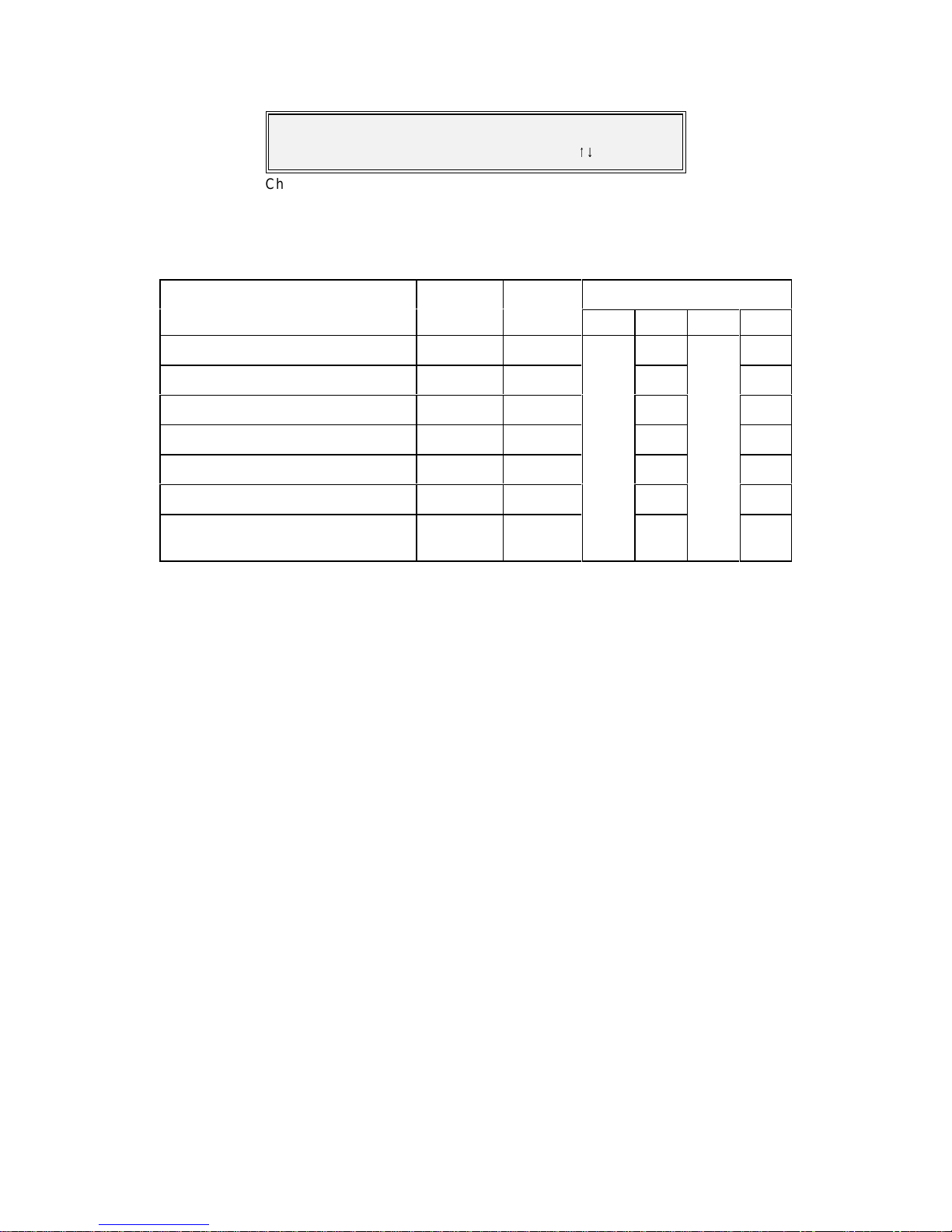
P300H P300 Series Modem Installation and Operating Handbook Page 67
Select Turbo Mode/Code rate, then (YES)
[0.750 Industry de-facto 3/4 rate]
89
Change, Tx/ Rx, Mod/Demod, FEC Rate Menu (Turbo)
For Turbo FEC the FEC rate selection screen i s as follows:
The T urbo FEC code rate may be selected from the scroll list of preset rates displayed on the screen.
pressing YES wi l l accept the current FEC rate and ret urn t o t he Change, Tx, M odulator menu. This list can
contain up to 31 different rates, but currently only the following are defined:
Screen Description Exact Delay Modulation Schemes from
code rate (bits) *
BPSK QPSK OQPSK 8PSK
“0.3125 Industry de-facto 5/16 rate” 0.3125 2662 V3.57 n/a
V3.57 V3.57
“0.477 Industry de-facto 21/44 rate” 21/44 4056 V3.57 n/a
"0.493 Paradis e ½ rat e" 2028/4116 4056 V3.40 n/a
“0.666 Paradis e 2/3 rate 2499/3748 4998 V3.57 n/a
"0.750 Indust ry de-facto 3/4 rate" 0.750 4446 V3.40 n/a
"0.789 Paradis e 3/ 4 rate" 3249/4116 6498 V3.40 n/a
"0.875 Paradise 7/8 rate" ** 0.875 450
(Low Latency) (yes 450)
V3.40 n/a
* Note on processi ng delay. Use the data rate before the FEC to determine t he delay in milliseconds from
the delay in bits. For example at 1Mbps using Rate 0.789 Turbo FEC, the FEC delay is (6498/1000000)
seconds, which is 6.5ms.
** N ote on Low L a t e n cy 7/8 Ra t e Tu r bo : A s Turbo FEC sc h eme s g o thi s is a relativ ely poor performer. BUT
it does provide about a 1dB performance improvement over 7/8 rate Viterbi, and for links where the
transponder space i s fi xed to accommodate a 7/8 Viterbi coded link, switching from Viterbi to Turbo will give
a useable 1dB improvement. It also provides significantly lower latency than subsequent Turbo schemes
(which offe r a better 7/8 rate performance at the cost of significant latency). If you’re stuck with a channel
that can only accommodate 7/8 Rate FEC, then this will give you an extra dB over us ing Viterbi.
Page 68

P300H P300 Series Modem Installation and Operating Handbook Page 68
6.6.12 Change, Tx/Rx, Mod/Demod, REED-SOLOMON Menu
This option is only available if the INTELSA T Reed-Solomon feature is available (standard P300-IBS and
above).
INTRODUCTIO N TO RE ED-SOLOMON
Reed-Solomon FEC is a powerful scheme `wrapped around` the normal inner FEC which may be used
to correct the remaining errors from the normal Turbo, Viterbi , Sequential, or TCM inner F EC. The code
rate is s peci fi ed by three values `n`, `k`, and `t`. These have a fixed relationship of n - k = 2t, so `t` is simply
half the difference between `n` and `k`. A typical code rate may be specified such as (n, k, t ) = (126,112,7).
RS e rror correction works on codewords (blocks) of bytes, where `n` is the length of the block of which
there a re `k ` bytes of original data, and 2t byt es of error correction information. The RS codec can correct
any byt es in error up to a value of `t`, so in the above example with t = 7, up to seven by tes within the 126
may be corrected no matter how many individual bits per byte are in error. Howev er, when the error rate
exceeds the correctable level, unlike other FEC schemes which degrade gracefully Reed-Solomon fails
dramatically. Once the error correcti on t hreshold is passed (eg 8 errors in our example block) the codec
considers it uncorrectable and passes the block uncorrected, ie the error rate goes from 0 to no error
correction in one step. There is a small transitional area where due to the distribution of the errors, the
errors in some blocks are just below the threshold (and therefore fully correctable) and for some blocks
just above (and therefore uncorrectable). In practice this effect gives a RS satellite circuit a transition from
error free to unserviceable in about a 1dB change in Eb/No.
In addit i on to t he (n,k,t ) speci fi cati on of the code rate, there is an additional parameter of interleaving depth.
Interl eav ing i s used to `mix up` the blocks so that a burst of errors affects a few bytes from several blocks,
rather than a lot of byt es from a single block. Int erleav ing is usually of depth 4 or depth 8. The configuration
menus are described in the followi ng paragraphs.
See also the applications section, para 8. 4 "Choos ing Optimum Custom RS N&k Values" on page 144
Page 69
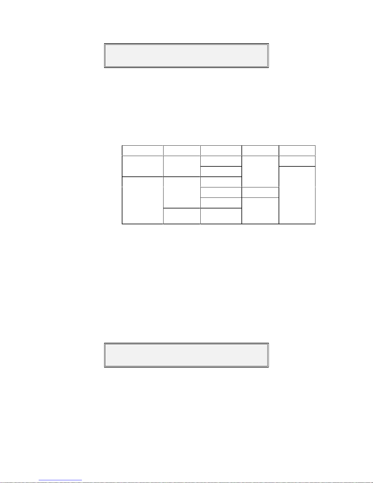
P300H P300 Series Modem Installation and Operating Handbook Page 69
Tx RS outer codec: [?]
1=Off 2=INTELSAT n,k,t & depth 3=Other
Change, Tx/ Rx, Mod/Demod, Reed-Solomon Menu
Scrambler: [?]
1=Off 2=Normal 3:Other
Change, Tx/ Rx, Mod/Demod, Scrambler Menu
The Reed-Solomon menu appears as follows:
The Reed-Solomon outer FEC codec may be configured as follows:
OFF The Reed-Solomon out FEC is disabled. Note that for testing the effectiveness
of the RS codec, a test mode allows you to disable the RS decoder error
corrections without removing t he RS overhead (which changes t he satellite data
rate and therefore to a small extent the Rx Eb / No).
INTELSAT T h is switches the RS codec on using standard INTELSAT values which are as
follows:
FEC Framing Data Rate (n,k,t) Depth
TCM Any
> 1544 kbps 8
(219,201,9)<= 1544 kbps
4
Non-TCM
eg Turbo, Viterbi,
Sequential, or No
FEC
IDR 1544 kbps (225,205,10)
2048 kbps
Other rat es
(126,112,7)
IBS or All rates
Closed Net
Note: When interworking with NEC modems in TCM mode (and IBS framing), NEC have chosen to use
Interleaving depth 4 for all data rates. For rates >1544kbps then it will be necessary to select `Other`, and
manually select the interleaving as depth 4.
OTHER This option is only available if the `Custom Features` feature is available
(standard on P300-TCM). Thi s feat ure allows the operat or to specify the code rate
outside of the normal INTELSA T parameters ie a fully variable code rate Reed-
Solomon codec. The l imitations are as follows `n` = [ 60 - 255], `k` = [n - (2, 4, 6,
8, 10, 12, 14, 16, 18, or 20)] ie `t`=1 to 10.
See the applications section, para 8.4 "Choosing Optimum Custom RS N&k
Values" on page 144
6.6.13 Change, Tx/Rx, Mod/Demod, SCRAMBLER Menu
The Scrambler selection is made from OFF, NORMAL, and CUSTOM.
OFF Turns off all scrambling, and whilst this may be used for testing or carrier line up,
it i s not normally used over satellite.
Page 70

P300H P300 Series Modem Installation and Operating Handbook Page 70
Toggle Scramblers:
1=IBS (Off) 2=RS (N/A) 3= V .35 (On) 4=Turbo (N/A)
Change, Tx/ Rx, Mod/Demod, Scrambler-Custom Menu
V.35 Styl e Scrambler [?]
1=CCITT 2=INTELSAT V.35 (Normal) 3=FDC 4=Linkabit
Change, Tx/ Rx, Mod/Demod, Scrambler-Custom V.35 Menu
NORMAL Selects the appropriate scrambler based on the current configuration, and
enables it (see table below).
FEC: No Reed-Solomon Reed-Solomon Active
Service type: Non Turbo Turbo Non Turbo Turbo
Closed Net (No ESC),
Closed Net + ESC (<32kbps),
IDR (& Custom IDR)
Custom IBS without TS32 MF
V.35 Scr Turbo Scr RS Scr RS Scr
IBS/SMS,
Closed Net + ESC (>=32kbps), IBS/SMS synchronous scrambler
Custom IBS with TS32 MF
The rationale behind this “NORMAL” option is deceptively simple: Following
Intelsats example of using Reed-Solomon with IBS or IDR, we have si mply used
the first synchronous scrambler in the t ransmit chain ev en when two or more are
avai lable. Also any synchronous scrambler is used in preference to t he V.35 self
synchronising scrambler, as this will multiply received errors degrading
performance.
Other Thi s allows non s tandard s crambler operation to match the configuration of other
non standard equipment which leads onto the following menus:
Pressing 1, 2, 3, or 4 toggles each available scrambler between On and Off. Scramblers which are not
available are shown as N/A (Not A vailable) as they are out of circuit (eg Reed-Solomon scrambler when
RS is Off). Thi s screen s pecifically allows you to enable more than one scrambler, in order that y ou might
match the (mi s)configuration of other equipment which allows the operator to accidentally switch multiple
scramblers on. When the V.35 sty le s crambler is enabled a subsequent menu is displayed.
This screen then allows selection between CCITT V.35, INTELSAT V.35, FDC (Fairchild), and Linkabit
types. Th ese are all different int erpretations of the poorly defined V.35 scrambler specified by the CCITT.
Unle ss you are trying to int e r-operat e with another manufacturers equipment known to have an incorrect
scrambler, select INTELSAT mode as this is the most common.
Ref er al so to section 8.9 on page 152 which describes in more detail the different scramblers, and
interworking between manufacturers.
The operator is warned of unus ual scrambler settings when SETUP-CHECK is requested.
Page 71

P300H P300 Series Modem Installation and Operating Handbook Page 71
Carrier: [?] 1=Off 2=On
3=Muted after pwr brk 4=Intfc RTS Controlled
Change, Tx, Modulator, Carrier M enu
Set Tx Power [-15.3dBm]
enter value ??.? (YES), or
89
to change
Change, Tx, Modulator, Power Menu (Normal)
Power from BUC (13-33), n o w [31]dBm
1:Set new power 2:Nudge up/down
Change, Tx, Modulator, Power Menu (Terminal with BUC)
6.6.14 Change, Tx, Modulator, CARRIER Menu
The state of the Transmit Carri er is selected as follows:
OFF The carrier is off.
ON The carrier will remain on, and after a power break it will automatically return t o
on.
POWER BREAK
MUTE The carrier is switched on BUT after a power cut the carrier will be switched off
and a deferred alarm generated until ei ther from the front panel or remotely the
unit i s instructed t o ret urn the carrier to the on state.
RTS
CONTROLLED The car rier will be dynamically controlled by the `Sig Valid In`, the RTS line on a
V.35 DCE interface (see interface card details in appendix A for line names for
other interfaces) . No alarm is raised when the Tx carrier is muted by the RTS line
going to the `off` state unless t he RTS li ne itself is se t to raise an alarm if it goes
to the off state (Change, Terr-Intfc, Control Lines).
The operator is warned if the carrier is set to POWER BREAK MUTE when SETUP-CHECK is request ed.
6.6.15 Change, Tx, Modulator, POWER LEVEL Menu
This is the normal menu for the P300 and P310 L-Band modem. An alternative menu is displayed when
operating in `Terminal` mode with a Paradise BUC.
This menu allows cont rol of the Transmit output power. This may be varied from 0dBm to -25dBm (-5dBm
to -30dBm for the P310) in 0.1dB st eps, ei t her by di rect entry of the required power or by us ing the up/down
keys to adjust the current value up or down in 0.1dB steps. Pressing the Up/Down keys rapidly causes the
level to change in 0.5dB increments. If AUPC is active (refer to AUPC in section 8.11.1 on page 154) then
the delta power added by t he AUPC is also dis played on the top line.
When the P310 is operati ng i n Terminal Mode (i e w ith a Paradise BUC and with the FSK option fitted to the
modem , and the Modem / BUC mode set to Terminal), the power level at the BUC is under closed loop
con trol . T he operator now enters the desired power at the BUC directly, and the modem operates in
conjunction wi t h the BUC, varying the Tx Carrier level and BUC attenuator to provide the desired power.
If a Paradi se B UC & FS K are fi tt ed, but the modem / BUC are set in independent mode, then a third screen
is displ a yed (similar to the 1st) from which the setting of the BUC attenuator may also be accessed by
pressing the down key from the power level menu.
Page 72

P300H P300 Series Modem Installation and Operating Handbook Page 72
Spectrum Invert [?]
1=Normal 2=I nvert
Change, Tx/ Rx, Spectrum Invert M enu
AUP C: 1:Mode 2:Max 3:M in 4:Slew rate
5:Target Eb/No 6:Tolerence 7:Loss act'
Change, Tx, Modulator, AUPC Menu
6.6.16 Change, Tx/Rx, Modulator, SPECTRUM INVERT Menu
This menu allows the Tx S pectrum to be inv ert ed, to cope wi th s atellites or frequency convers ion equipment
which al so inverts the spectrum. Note that apart f r om t h e f a c t that the modem will not lo c k on t o a n
inverted spectrum, on a spectrum analyser t he carrier is to all appearances unchanged.
The operator is warned if SPECTRUM INVERT is act ive when SETUP-CHECK is requested.
NOTE ON BPSK SPECTRUM INVERSION
True spectrum invers ion does not affect BPSK signals and so i n BPSK mode there is no requirement for
a true spectrum invert feature. Instead in BPSK mode (to be compatible with other manufacturers
equipment), the Tx Spectrum Invert option reverses the ordering of the pairs of Tx data symbols from the
FEC encoder to the modulator. The `Normal` option is compatible with other manufacturers BPSK
equipment. The Invert option (ie reverse pairs of Tx symbols) is compatible with earlier Paradise products
such as the P200 (which we consider to have the `correct` symbol pairing !). On the Rx path the symbol
pairing is automatically determined, and s o t he Rx Spectrum Invert feature has no effect in BPSK.
If int erworki ng w i th ot her manufacturers equipment it is worth reading the notes in the s ect ion “Interworking
different manufacturers equipment” on page 153 which covers primarily scrambling, but also the
requirements for Spectrum Invert with V iterbi/Sequential in BPSK and QPSK.
6.6.17 Change, Tx, Modulator, AUPC (Software >=V2.12)
This menu is only displayed if the AUPC feature is available. It is advisable to refer to the introduction to
AUPC in sect ion 8.11.1 on page 154 before enabling this facility.
Note tha t op tions 2 through 7 only display when the AUPC m ode It is set to other than Off or Monitor
Distant, so initially only “AUPC: 1:Mode” may be displayed.
Page 73

P300H P300 Series Modem Installation and Operating Handbook Page 73
Set AUPC Mode: [Off]
1=Off 2=Mon dist' 3=Maint' EbNo 4=Self mon
Change, Tx, Modulator, AUPC Mode Menu
Set AUPC max positive delta po wer
[3.5dB] (0-25.0dB) ??. ? d B (Yes)
Change, Tx, Modulator, AUPC, M ax Menu
6.6.18 Change, Tx, Modulator, AUPC, MODE Menu
NOTE: You probably need permissi on from the satellite operators to use AUPC unless you have a blanket
power budget which you may use as you see fit.
The modes are as follows:
OFF The modem disables the Auto Uplink Power Control, the Tx power will not adjust
dynamically. Any AUPC positive or negative delta power adjustment to the Tx
output pow er It is removed instantaneously (ie a Tx power step). Any bandwidth
within the ESC channel used by t he AUPC It is released back for ESC usage.
MON DIST' The local modem utilises the as ync ESC channel between the local and distant
modems to regularly collect Eb/No and BER data from the dis tant modem. This
can be displayed with Monitor, Distant Eb/No & BER. This It is not an `active`
AUPC mode and the Tx power w ill not adjust dynamically, i t simply allows local
monitoring (and logging) of distant performance.
MAINT Eb/No This It is full AUPC mode. As with MON DIST' above it uses the ESC channel to
collect Eb/No information from the dist ant modem, but in addition it varies the Tx
power within the constrai nts provided to maintain a specifi ed distant Eb/No.
SELF MON This It is ONLY used in Tx only applications (typically point to multipoint) to
attem pt to maintain the Eb/No at (multiple) Rx only stations. It requires the
modem to be able to receive the its own carrier via satellite (not by any form of IF
loop). In operation it monitors the local Rx Eb/No and adjusts the local Tx power
to keep this local Eb/No const ant. This means it can compensate for atmospheric
cha nges which affect the Tx signal to the satellite, and LOCAL atmospheric
changes affecting the Rx signal from the satellite. If however (as It is comm on)
ther e are m ultiple Rx terminals over a wide geographical area, then different
atmospheric conditions over each terminal will still cause a variation in the Eb/No
for each terminal.
Note: See AUPC in sect ion 8.11.1 on page 154 regarding the async ESC channel requirements in order
for local modem to distant modem communications in order for modes `Mon Dist` and `Maint Eb/No` to
operate. Note also that the distant modem must be set for remote reporting of Eb/No with Change, Rx,
Demod, AUPC.
6.6.19 Change, Tx, Modulator, AUPC, MA X Menu
This allows the max i mum additional power that the A UP C can use to maintain the dis tant Eb/No to be set.
Set this so that the total maximum power (ie the nominal power s et with Change, Tx, Mod, Power PLUS
the AUPC Max positive delta power) It is within the constraints put upon your carrier by the satellite
operators.
Page 74

P300H P300 Series Modem Installation and Operating Handbook Page 74
Set AUPC max negative delta power
[1.0dB] (0-25.0dB) ??. ? d B (Yes)
Change, Tx, Modulator, AUPC, M in Menu
Set maximum power slew rate: [10]dB/min
(0.1-99.9dB/min, 0=no limit) ??.? (YES)
Change, Tx, Modulator, AUPC, Slew Rat e Menu
Set target Eb/ No to m a i n tain: [8.5]dB
(0 to 25.0dB) ??.?d B (Yes)
Change, Tx, Modulator, AUPC, Target Eb/No Menu
Set Eb/No tolerance before AUPC action:
[±0.5dB] (0.1-25.0dB) ±??.?dB (Yes)
Change, Tx, Modulator, AUPC, Tolerance Menu
6.6.20 Change, Tx, Modulator, AUPC, MIN Menu
This allows the mini mum delta power that the AUPC can us e t o maint ain the distant Eb/No to be set.
Norma lly the maximum delta power It is set to give the distant Eb/No a boost in poor atmospheric
conditions, with any improvements in Eb/No caused by particularly good atmospheric conditions being
considered a bonus. I t is it not normally necessary to set the minimum delta power to any figure other than
zero ot herwise any beneficial gain in Eb/No caused by good atmospheric condit ions will be negated by a
decrease in Tx power.
This facility only exists so, if as a condition of being able to use AUPC, the satellite operator has asked you
to provide a reduced power i n particularly good atmospheric conditions at your geographic location. This
may be in an atte mp t to `balance out` any i ncreas e in power required for other locati ons where there may
be poor atmospheric conditions, with the AUPC in those locations requiring additional power from the
satellite.
6.6.21 Change, Tx, Modulator, AUPC, SLEW RATE Menu
This facility allows the changes in Tx pow er to occur at a controlled slew rate to prevent s tep changes in
Tx power at the IF out put. A value of zero indi cat es no limit and step power changes will occur. Whatever
the slew rat e limit the power changes wi ll remain within the M ax and Min power limits set on the previ ous
two screens. Use caution when setting this parameter so that the slew rat e you impose It is not too great
to prevent t he AUPC system responding to rapid fades (eg 10dB fade in 10 seconds).
6.6.22 Change, Tx, Modulator, AUPC, TARGET EB/NO Menu
This s creen allows the target Eb/No to be set. This It is the distant Eb/No when the AUPC mode It is set t o
Maint' Eb/N o, and the local Eb/No when set to Self Mon. This It is the target Eb/No the AUPC will adjust
the Tx pow er wi t hi n the M ax, Min, and Slew rate limits (once the Eb/No goes outside the Tolerance wi ndow
set below) to try and restore this figure.
6.6.23 Change, Tx, Modulator, AUPC, TOLERANCE Menu
Page 75

P300H P300 Series Modem Installation and Operating Handbook Page 75
Set AUPC power on carrier lost: [Nominal ]
1=Freeze 2=Nominal 3=Maximum
Change, Tx, Modulator, AUPC, Comms lost action M enu
This sets a ` tolerance window` on the monitored Eb/No. The AUPC will only attempt to restore the
monitored Eb/No to the t arget E b/No w hen the monitored Eb/No moves outside the tolerance window. This
It is to prevent the AUPC continuously adjusting the power to compensate for minor normal Eb/No
variations.
When the monitored Eb/No moves outside the tolerance window the AUPC will attempt to restore it back
to the target value (ie not just back i nside the tolerance window again).
6.6.24 Change, Tx, Modulator, AUPC, CARRI E R LOST ACTION Menu
This screen sets what action the AUPC It is to take locally if it looses comm unications with the distant
modem (ie presumably there It is a significant fade and the distant demod has lost lock).
FREEZE The carrier power It is frozen at its current value.
NOMINAL The AU PC de lta power It is reset to zero so the carrier returns to its nominal
power.
MAXIMUM Th e AUPC delta power increases to the maximum power limit as set on the
AUPC Max positiv e delta power screen.
Page 76

P300H P300 Series Modem Installation and Operating Handbook Page 76
ESC/Aux: 1:Define 2:Async ES C
3:Interfaces 4:Audio levels 5:Back’ alm
Change, Tx/Rx, ESC/Aux/BA Menu (IBS/SMS/IDR)
ESC Channel (overh ead is 2.39%):
1:Asyn c[2400,8,N] 2:Interface[RS485] 3:Audio
Change, Tx/ Rx, ESC/Aux Menu (Closed Net Plus ES C)
6.6.25 Change, Tx/Rx, ESC/AUX/BA Menu
This d ialogue is not available when the service is set at Normal Closed Network, and differs between
Clo se d N et Plus ESC, IBS/SMS and IDR s ervices. The IBS/SMS and IDR menu appears below, but some
options may not be displayed depending on how the modem Servi ce is defined:
In Closed Net Plus ESC mode a slightly different screen is displayed including the overhead percentage
required to support the ESC rate as set :
DEFINE Enabl e & Disable the ESC & Aux ports, specify the port usage (eg IDR sync or
async ESC), and allocate different parts of the overhead to each port. In Closed
Net Plus ESC the ESC channel is already defined to use as much of the overhead
as p ossibl e a nd the Aux channel is not available so the Define option is not
required (and is not offered).
ASYNC ESC When the ESC port is set for async operation this selection configures t he async
character format and Baud rate.
INTERFACES Set the electrical interfaces for each port, for the ESC port control if it is directly
internally li nked t o the M&C port for distant end M&C
AUDIO LEVELS Set the levels or the A udio port, both i n when used for IDR ESC and when used
direc tl y to generate a 64kbps carrier (2 x Audio only) or 128 kbps carrier (2 x
Audio + 64k data)
BACK' ALM Configure the four Tx backward alarms to map to the external input ports, or be
di rectly connected to t he Rx fault status of this modem (saves external patching
in non-multidestinational carriers). This option is on t he Tx menu only and again
is not s hown in Closed Net Plus ESC mode.
Page 77

P300H P300 Series Modem Installation and Operating Handbook Page 77
IDR 8k ES C: [?]
1=Off 2=Sync 3=Async
Change, Tx/Rx, ESC/Aux/BA, Define (IDR), ESC Menu
Tx Aux Circuit: [ ?]
1=Off (normal) 2=64K in V1&2 3=32K in V1 4=32K in V2
Change, Tx/Rx, ESC/Aux/BA, Define (IDR), Aux Menu
IDR M O DE ESC & AUX PORT DEFINITIONS
6.6.26 Change, Tx/Rx, ESC/Aux/BA, DEFINE (IDR) Menu
When operating in IDR or Custom IDR modes, the Define s election is as follows:
OFF The ESC port is disabled (and all ones is sent in the 8k ESC channel)
SYNC Normal 8k synchronous access i s provided on the ESC port.
ASYNC T his option is only available of the Async ESC feature is available (standard on
P300-IBS and above). The ESC interface is set to be asynchronous. The exact
Baud rate it can support varies with the asy n c character format set on t he Async
ESC menu. Typically wit h 8 bits per character (or 7 + parit y) it w ill support 4800
Baud, but with 8 bits plus parity, it will operate to 9600 Baud.
The reason for this strange situation is as follows: The async data is carrier
synchronously across the 8k ESC link at 9 sync bits per async character (start
+ 8 data bits, no stop or parity). At 9600 Baud with 8 bits/char there are a
maximum of 960 async characters per second (9600 / 10 [ start + 8 bits + stop]).
960 async characters per second requi res 9 x 960 sync bits per second to convey,
unfortunately 8.64kbps above the 8kbps channel capacity and so characters wi ll
be lost. At 9600 Baud with 9 bits/char (ie 8 plus parity) there are 872 async
cha racte rs per second (9600 / 11 [start + 8 bits + parity + stop]). 872 async
characters per second requires 9 x 872 sync bits per second to convey, 7.85kbps,
and so no characters wi ll be lost ov er the 8K ESC channel. So when set for [8 bits
No Parity ] or [7 bits with Parity] the maximum standard Baud rate i s 4800 Baud.
When set for [8 bits with Parity] the maximum standard Baud rate is 9600 Baud.
This is followed by the Aux port definition screen:
The Aux port can provide a 32kbps or 64kb ps synchronous data circuit i n place of one or both of the Audio
ESC channels:
OFF (NORMAL) The Audi o ESC channels operate as normal, the Aux port is disabled.
64K IN V1+V2 Both ESC Audio channels are disabled, and the Aux port operates at 64kbps.
32K IN V1 Audi o ESC V2 operates as normal, and the Aux port provides a 32kbps channel
in V1.
32K IN V2 Audi o ESC V1 operates as normal, and the Aux port provides a 32kbps channel
in V2.
Page 78

P300H P300 Series Modem Installation and Operating Handbook Page 78
Tx Aux P o r t: [? ] 1=O ff
2=INTELSAT low rate channel 3=Sync Channel
Change, Tx/ Rx, ESC/Aux/BA, Define (IBS), Aux Menu
ESC Port [?]:
1=Off 2:High Rate async channel
Change, Tx/ Rx, ESC/Aux/BA Define (IBS), ESC Menu
IBS MODE ESC & AUX PORT DEFINITIONS
6.6.27 Change, Tx/Rx, ESC/Aux/BA, DEFINE (IBS) Menu
When operating in IBS or Custom IBS modes, t he Define selection is as follows:
OFF The Aux port is dis abled.
INTELSAT The Aux port provides the `low rate ESC` definition in IESS309 (which t hen refers
back to IESS 403). I n t hi s mode only TS32 bit 1 of the overhead is allocated to the
Aux port, which provides an oversampled async interface at a maximum Baud
rate of approx 1/2000th the main data rate. Note that even in this mode a clock
is available, and the port may be used synchronously (at 1/480th the data rate)
if required.
SYNC CHANNEL Thi s o p t ion i s only avai lable if the IDR option is fitted (standard on P 300-IDR and
above) as it requires the `Clock/Data/Octet` Aux port on the IDR option to provide
the synchronous Aux interface (the single `Data` line us ed for t he oversampled
INTEL SAT ESC on the Async ESC connector cannot provide a synchronous
in terface) . If selected the Aux port operates synchronously, and varying amounts
of the IBS ov erhead may be allocated to the sync Aux channel. The sync channel
may utilise at up to a total of 21/32nds of the overhead which with Standard
IBS/SMS this allows the Aux port to operate up to 4.375% of the main dat a port
rate. The selection of the ov erhead available to the Aux channel is made following
the next menu (which specifies the ESC port), allowing the overhead to be
allocated between the Aux port and ESC ports.
This menu is followed by
OFF The ESC port is disabled
HIGH RATE
ASYNC The ESC Channel provides the `P aradise High Rate ESC`, which in a later menu
ma y be configured to be compatible with earlier products such as the P230,
P230D/I, and P1300/P1361 combination. This provides an async channel with
ma ximu m Baud rate approximately the terrestrial rate / 23 (eg usable rates of
2400 Baud at 64 kbps and 9600 Baud at 256 kbps ). One of the prime uses for this
ESC channel is to link it to the M&C port of the Modem (software controlled
inter n al l ink), and provide remote M&C of the distant equipment from the local
end of the link.
Page 79

P300H P300 Series Modem Installation and Operating Handbook Page 79
Sync Aux circuit o/h usage: [?]
1=Maximu m 2:Custom
Change, Tx/ Rx, ESC/Aux/BA Define (IBS) Aux usage Menu
Async ESC: [?]
1=P230 compatible 2=Cust om 3=All avail o/h{ after Aux}
Change, Tx/ Rx, ESC/Aux/BA Define (IBS) ESC usage M enu
The following menu's depend on the selections made for the Aux & ESC channels
If the ESC port is OFF and the Aux port is set to Sync Channel then the following menu selects the
overhead ass igned to the Aux port:
MAXIMUM Th e m aximum 21/32nds of the overhead is allocated to the Aux channel. This
comprises T S16, TS32 bits 1, & 5-8, and TS48. Giving an Aux port synchronous
data rate of 4.375% of the main data rate. If used asynchronously (ie
oversampled as wi t h the INTELSAT defini t ion), the asy nc rat e may be up t o 1%
of the main data channel rate, ie approx 600 Baud at 64kbps.
CUSTOM This option is only available of the `Custom Features` feature is available
(st andard P300-TCM). The overhead can be operator assigned to the Aux port,
varying the overhead as defined in the paragraph title "Custom Overhead
Allocation" a few paragraphs further on. If the ESC port is defined as Custom,
then this one screen allocates overhead between the Aux and ESC ports.
If the ESC port is set to High Rate Async and the Aux port is set to Sync Channel then the following
menu allows the overhead assigned t o t he ESC port to be determined.
P230 COMP' The standard 20/32nds of the overhead is allocated to the ESC and this is
compatible with earlier products such as the P230, P230D/I, and P1300/P1361
com b ination. The overhead allocated to the ESC is TS16, TS32 bits 5-8, and
TS48. TS32 bit 1 i s not used as thi s is reserved for the INTELSAT low rate ESC
(on the Aux port if so configured). The ES C port provides an async channel wit h
ma ximu m Baud rate approximately the terrestrial rate / 23 (eg usable rates of
2400 Baud at 64 kbps and 9600 Baud at 256 kbps ).
CUSTOM This option is only available of the `Custom Features` feature is available
(stan dard P300-TCM). A subsequent screen allows the operator to assign the
overhead to t he ESC port , varying the overhead as defined in the paragraph t itle
"Custom Overhead A llocation" which follows. If the Aux port is also set to Sync
Channel then this one screen allocates the overhead between the Aux and ESC
ports.
ALL AVAIL All the available overhead is assigned to the ESC channel. if the Aux port is
defined as Sync Channel then the s electi on reads All Avail after Aux, and when
the operator has defined the overhead allocated to the Aux port, any remaining
is allo cated to the ESC port. If using the Custom, IBS, Minimum overhead mode,
where the ov erhead rate v ari es to accommodate the ESC Baud rate defined, then
setting the ESC to All Avail maximis es the proportion of the overhead available
to the ESC, and low ers the overhead addition to the minimum possible.
Page 80
P300H P300 Series Modem Installation and Operating Handbook Page 80
O/h use: 1=TS16=XXX 2=TS32b5&6=XXX (YES)
3=TS32b7&8=XXX 4=TS48=XXX
9
More/Help
Change, Tx/ Rx, ESC/Aux/BA Define (IBS) ESC/Aux Custom 1
O/h use: 1=TS0b1=XXX 2=TS32b1=XXX
3=TS32b3=XXX 4=TS32b4=XXX
8
Back 9Help
Change, Tx/ Rx, ESC/Aux/BA Define (IBS) ESC/Aux Custom 2
6.6.28 Custom IBS Overhead Allocation
Several of the above paths lead to the following screen where the available overhead can be allocated
between the Aux port (if set to Sync Channel) and the ESC port (if set to Custom). This option is only
avai lable of the `Custo m Features` feature is available (standard P300-TCM).
This sophisticated facili ty allows the operator for example to:
'
On high rate links speci fy a low proporti on of the overhead to be assigned to the ESC channel (still
enough to provide the require asy nc Baud rate) but then allocate the remaining overhead to the
Aux port confi gured for a S ync Channel, allowing ex ternal access to the rest of the overhead for
example other data or BER testing (i nt ernal or external).
'
When using Custom, IBS, Min overhead, allocate the overhead between ESC & Aux ports. The
overhead wi ll scale to prov i de the set ESC Baud rate however much of the overhead is assigned
to it, and i ncrease / reduce the to tal overhead as appropriate. The remainder of the overhead can
be a l located to the Aux channel, again for extra data of BER testing (internal or external). This
effectively allows the syn c channel rate to be varied (by changing the ES C rat e & overhead ESC
assignment, w hich the overhead then adjust s to provide).
The screens are as follows:
Eac h of the `XXX` fiel ds can displ ay the fol lowing u ses for th at part of the overhead, and be toggled
between the different uses by pressing the appropriate numbered key:
--- The overhead locations are unused
ESC Defined for use by the ESC port
Aux Defined for use by A ux port
CAS In use for Channel Associat ed S ignalling
B/A In us e for t he Backward Alarm
MFW In us e for t he TS32 Multi Frame Word.
TS16 and TS48 ar e bot h bytes of the overhead structure which are free when CAS is not in use, they are
each equivalent t o 8/32nd of the total overhead and can be allocated to ESC or Aux.
TS32 bits 5 and 6 (allocated together) and bits 7 and 8 (allocated together) both correspond to 2/ 32nds
of the overhead. These are normally spare, s ee note 1, and can be allocated to ESC or Aux .
TS0 bit 1 is 1/32nd of the overhead, and are normally spare again see note 1. This bit can only be
allocated to the ESC.
TS32 bi t 1 is 1/32nd of t he overhead, and is t he bit allocated by INTELSAT for the low rate oversampled
ES C (availab le on the Aux port if so configured). Spare if the Aux port is not set t o INTELSAT mode or
Note 1, can be allocated to ESC or Aux.
TS32 bit 3 is 1/32nd of the overhead and is normally used for the backward alarm, but is spare if Custom
IBS mode is selected, and the backward alarm facility has been disabled. This bit can only be
allocated to the ESC.
TS32 bit 4 is 1/32nd of the overhead and is normally used for the Satellite TS32 Multiframe but is spare
if Cust om IBS mode wi t hout a TS32 multiframe is selected. This bit can only be allocated to the ESC.
Page 81

P300H P300 Series Modem Installation and Operating Handbook Page 81
Max ESC rate=2650 Baud (YE S )
Au x sync rate=1387b p s, asyn c=346 Baud
Change, Tx/ Rx, ESC/Aux/BA Define (IBS) ESC/Aux Custom 1
Async ESC port:
1:Baud rate [2400] 2:For m at [8,N] 3=Set as M&C por t [=]
Change, Tx/ Rx, ESC/Aux/BA, C.g. , Async Menu
Note 1: Spare u nless the uni t is configured for 2048kbps, IBS G.732 mode, with s pare bits of TS0 set
to transparent (when these bits carry the spare bit s).
To summarise:
In standard IBS modes up to (8+8+2+2+1+1) bits = 22/32nd of the overhead may be allocated to the
ESC port, and up to (8+8+2+2+1) bits = 21/32nds of the overhead may be allocated to the Aux
port. 21 of these bits are shared between E S C & Aux.
In Custom IBS modes (wit hout backw ard alarm or TS32 multiframe) up to (8+8+2+2+1+1+1+1) bits
= 24
/32nd of the overhead may be allocated to the E SC port, the Aux port is as above for Standard
IBS, and 21 of t hese bits remain shared between ESC & Aux.
When the overhead has been ass i gned as requi red, press the YES key whi ch provides the following screen:
This summarises the ESC & Aux port rates based on the overhead assignments just made:
The Max ESC Baud Rate is the maximum continuous rate the ESC channel will support, the ESC
channel must be set to a standard async Baud rate equal or below this figure using the Async ESC
menu selection.
The Aux Sync Rate is the dat a rate of the Aux port. A DPLL generates this clock however obscure the
rate !
The Au x async Baud is the max imum Baud rate that could be conveyed through this A ux channel, if
the Aux cl oc k is ignored and the Aux port is used in oversampled async mode (as defined by
INTELSAT for the low rate IBS ESC).
The Au x S y n c R a te and Aux async Baud information display is not available in early versions of the
embedded M&C code.
6.6.29 Change, Tx/Rx, ESC/Aux/BA, ASYNC ESC Menu
This menu allows the asy nc parameters for the ESC i nt erface to be defined.
BAUD RATE All ows the ESC Baud rat e to be set (see below), the current Baud rate setti ng is
displayed.
FORMAT Allow the async character format for the ESC port to be set (see below), the
current asyn c character format is displayed.
SET AS M&C When selected this copies the remote M&C async settings to the ESC port, to
si mp li f y usin g the E S C po r t fo r re mot e M&C. This is a one time copy, and the ESC
port configurati on will not track changes to t he remote M&C configuration. When
the ESC port is c onfigured as the remote M&C port, [=] appears, when not equal
[
…
] appears.
Page 82

P300H P300 Series Modem Installation and Operating Handbook Page 82
ESC Baud rate: [2400]89 (YES)
(Max continuous rate is 2962)
Change, Tx/ Rx, ESC/Aux/BA, Cfg. As ync, Baud Rate Menu
Asyn c F o rmat: [7 bits, No parity]
1=7 bits, 2=8 bits, P arity: 3=None, 4=Even, 5=Odd (Yes)
Change, Tx/ Rx, ESC/Aux/BA, Cfg. Async, Format Menu
NOTE: ESC channel not
guaranteed above 2962 Baud (YES)
Change, Tx/ Rx, ESC/Aux/BA, Set as Remote Warning M enu
6.6.30 Change, Tx/Rx, ESC/Aux/BA, Config Async, BAUD RATE Menu
This menu allows the Baud rate for the external interface to the ESC channel to be set. Any rate can be s et,
although the maximum continuous rate supported is stated (calculated from the terrestrial rate, and async
character format).
Refer to section 8. 6 "Det ermining exact maximum ESC Baud rates" on page 146
6.6.31 Change, Tx/Rx, ESC/Aux/BA, Config Async, FORMAT Menu
The ESC async character format may be edited by pressing 1 or 2 to select 7 or 8 bits, and 3, 4, or 5 to
sele ct No parity, Even parity, or Odd parity respectively. Note that as described in the last paragraphs
shortening t he async character reduces the maximum continuous Baud rate, as the ESC channel is limited
to a finite character rate per second, and the more bits in each async character, the higher the effective
Baud rate allowed without exceeding the ESC channel character rate limit.
6.6.32 Change, Tx/Rx, ESC/Aux/BA, Config Async, SET AS REM M&C
This option sets the ESC channel async parameters to match the settings on t he Remote M&C port. This
is speci fi cally i ntended t o si mplify remote M& C wi t hi n the IBS/SMS overhead via t he E SC channel. Note this
is a `one time` setting, and if the remote M&C parameters are varied, the ESC c ha n n e l will not fo llow
them. I f the remote M& C Baud rate exceeds the maximum continuous ESC rate, then the following warning
will be issued, although the copying of t he parameters w ill go ahead.
Page 83

P300H P300 Series Modem Installation and Operating Handbook Page 83
Tx & Rx ESC Interface: [L i n k-R]
1=RS232 2=RS422 3=RS485 4:Lin k to remote M&C
Change, Tx/ Rx, ESC/Aux/BA, Cfg I nt e rfaces, ESC Menu
Internal link to M&C Por t: [L o cal]
1=Local M&C P C end 2=Remote end
Change, Tx/ Rx, ESC/Aux/BA, Cfg I nt erfaces , ESC, Link to M &C
Au x Interface: [RS232]
1=RS232 2=RS422
Change, Tx/ Rx, ESC/Aux/BA, Cfg I nterfaces, Aux Menu
6.6.33 Change, Tx/Rx, ESC/Aux/BA, I NTERFACES Menu
This leads to the s election of the ESC and Aux interfaces. The interface selection screens are only shown
for active p orts, and so either or both may show in turn dependi ng on how the ports are defined for use. If
both are act ive then the ESC interface is selected first. NOTE that these are some of the few menus which
appears on both Tx & Rx menu trees, but for w hich the setti ng is common to both !
ESC Interface
All options exc ept 4 are self explanatory, [Link-R] means Link-Remote and [Link-L] Link-Local. Option 4
leads onto the following menu:
This inst ruct s the Modem make an internal link between the ESC port and the remote M&C port. It must
be set specifically for the end of the link the modem is located at. When either of these options are
selected, the physical ESC port i s disabled, as i t is linked internally to the M&C port.
LOCAL Incoming messages (on this modems remote M&C port Rx lines from the M&C
Ma s t e r de vice) a re r ou t e d d i r e ct ly to th e T x ESC channel and out over the satellite
link. M essages from the i ncoming satellite link on the Rx ESC channel are routed
onto the Tx output lines of the remote M&C port, to return the responses to the
Master M&C device.
REMOTE Messages from the incoming satellite link on the Rx ESC channel are driven onto
the remote M&C port Rx (input) lines, allowing any devices daisy chained to the
rem ote M&C port to receive a message (including this modem). Messages
present on the remote M&C port Tx (output) lines, which includes any respons e
from this unit or any device daisy chai ned t o the remote M&C port, are routed to
the Tx E S C channel and back via the satellite link.
Au x Interface
Following the ESC interface selection the Aux port may be configured (s elf explanatory):
Page 84

P300H P300 Series Modem Installation and Operating Handbook Page 84
Au d i o levels: V1=-12.3dBm V2= 5. 6dBm
Press 1 or 2 then level
89
, YES to fi x
Change, Tx/ Rx, ESC/Aux /BA, Audio Levels Menu
6.6.34 Change, Tx/Rx, ESC/Aux/BA, AUDIO LEVELS Menu
This s creen is used to set the levels for the Audio ESC ports. These are typical used in IDR modes for the
Audio ESC c hannel s, but may also be used when generating a 64kbps IBS carrier (comprising of 2 x
32kbps ADPCM audi o channels only ), or a 128kbps (comprisi ng of 2 x 32kbps ADPCM audio channels plus
64kbps from the main data port.
Press 1 or 2 to select which channel, then use the Up and Down buttons to vary the level. Pressing the
up/down keys slowly/rapidly causes the level to change in 0. 1dB steps, rapidly in 0.5dB steps. YES must
be pressed to exit the screen otherwise the p revious values will be restored.
Page 85

P300H P300 Series Modem Installation and Operating Handbook Page 85
Back’ Alm 1234: [?] E=Ext A=Auto O=OK
1=EEEE 2=AEEE 3=AOOO 4=AAAA
Change, Tx/ Rx, ESC/Aux/BA, Backward A larm Menu
6.6.35 Change, Tx/Rx, ESC/Aux/BA, BACKWARD ALARMS Menu
This screen i s us ed to confi gure the four backward alarm inputs used in multi-destinational I DR or for lower
rate multi-destinational operation in some of the Custom IBS modes.
This screen i s at firs t di ffi cult to understand, but is relati vely si mple. It allows t he four backward alarm input
to be mapped in certain ways, without any external backward alarm patching:
On the screen the letters mean as follows:
E=Ext: External patch, the state from the backward alarm connector on the rear panel
connector will be sent (open ci rcuit = OK, Ground = fail)
A=Auto: Auto, the alarm will be sourced internally from the summary Rx fail signal
O=OK: The alarm will always send the `OK` condition.
So the menu choices are as follows:
EEEE All four alarms report the stat e from the Backward Alarm connector on the rear
of the equipment . Use when transmitting a multidestinational carrier, but
where the carrier we are receiving does not correspond to the destination
all ocate d backward alarm channel 1. The Rx fail signals from the modems
rece ivin g t he c ar r i e r s fr o m all t h e o t h e r d e s t inati o ns (includi ng this modems Rx fail
signal) m ust be externally patched into the corresponding external backward
alarm inputs.
AEEE Alarm 1 is internally connected to the Rx F ail signal, alarms 2-4 are available for
external patching. Use when this station is transmitting a multidestinational
carrier, where the carrier we are receiving corresponds to the destination
allocated bac k ward alarm cha nnel 1. The Rx fail signals from the other modems
receiving the carriers from all the other destinations must be externally patched
into the corres pondi ng external backward alarm inputs 2-4. If the external inputs
2-4 are open circuit, then this is the same as AOOO below.
AOOO Ala rm 1 is internally connected t o the Rx Fai l signal, alarms 2-4 always send the
OK sta te. Used in non multidestinational working, external backward alarm
inputs are ignored.
AAAA All four alarms represent the internal Rx Fail signal. Used in non
multidestinational working, external backward alarm inputs are ignored.
In non multidestinational operation, the choice between the third and fourth options is down to operator
preference or station poli cy.
Page 86

P300H P300 Series Modem Installation and Operating Handbook Page 86
Rx: 1:Service 2:Baseband 3:Buffer/ Clocking
4:Demod 5:ESC/ Aux 6:Rx=Tx [Off]
Change, Rx Menu (Rx not set to follow Tx)
Rx: 1:Baseband 2:Buffer/Clocking
3:Demod 4:Rx=Tx [On]
Change, Rx Menu (Rx set to follow Tx)
6.7 CHANGE, RX MENU
Many of the Change Rx Menus are identical to t he Change Tx menus, and a reference is made back to the
Change Tx description rather than repeat t he text unneces s arily.
NOTE ON RX=TX FUNCTION
The Change, Rx M enu has an extra feature over the Change Tx, namely the abi lity for the Rx path to track
the majority of the Tx configurati on parameters (Rx=Tx) to simplify t he configuration in s ymmetrical links
(ie the m ajority). If Rx=Tx is activated then the following Rx parameters automatically track the Tx
parameters:
Service: All modes
Baseband: Continuous: data rate. Drop/Insert: all selecti ons excluding the timeslots.
Mod/demod: Modulation, Inner FEC type & FEC Rate, Outer RS FEC, Scram bler, Spectral
Invert
ESC/Aux/BA: All parameters
Rx parameters w h ich specifically remain i ndependent are:
Baseband: Insert timeslot selection (only if Drop/Insert activ e)
Buff/Clk: Rx Buffer size & clocking mode
Demod: IF Frequency & S weep control
Note that setting Rx=Tx even momentarily copies the Rx parameters which track the Tx to the Rx
configuration. Toggling thi s opt i on on then off again provides a convenient way to copy the Tx config to the
Rx (except the IF frequency) should this be required at any point.
The Change, Rx menu then will have different options showing depending on whether Rx=Tx mode is
active:
Rx=Tx Disabled
Note that opti ons 2-5 on the top menu are only di splay ed w hen the SERVICE option is set to something other
then Off, and so i nitially the screen m ay only show the SERVICE and Rx=Tx options.
Rx=Tx Enabled
In this mode:
The Baseband option i s only shown i f t he Tx baseband mode is set to Drop Mux , and hence t he Rx
Insert Mux will be active and the operator needs access to the baseband menu in order to
independently s et the insert TS s election.
The Buffer/Clocking menu is always shown.
The Demod menu provides access to the independent selection of IF Frequency, and demod Sweep
Width control
Note: If Rx=Tx is enabled, and
the Tx S erv i ce i s set to Off, then only the Rx=Tx selection will be the only
one displayed.
Page 87

P300H P300 Series Modem Installation and Operating Handbook Page 87
Insert bearer : [?]
1=Loop Terr 2=Generate internally
Change, Rx, Baseband, I nsert Mux, Bearer Route M enu
Is all Rx data for this destination: [?]
1=All 2:Partial
Change, Rx, Baseband, Insert Mux, Partial Insert Menu
6.7.1 Change, Rx, SERVICE Menu
See "Change, Tx/Rx, Service Menu" on page 54
6.7.2 Change, Rx, BA SEBAND Menu
The Continuous & Other menu options are identical to the Tx s elections, see "Change, Tx /Rx, Baseband
Menu" on page 57
The Insert Mux sele ction i s t he same as the Drop Mux selection except the prior to the same dialogue as
on the Tx pat h tw o other ques ti ons are asked: Bearer routing (Loop Terr or Generate) & Partial Insert (All
or Partial). These are des cribed as follows:
Bearer Routing
The bearer to the Inse rt M ux can either be looped from the Drop Mux, or generated internally. The following
prompt is dis played:
In most si tuat i ons Loop Ter r is selected, and the receive data is ins ert ed onto the same bearer from which
the Tx data was dropped. This however forces the receive data to be passed to the terrestrial using the
terrestri al clock (which i s already clocking the bearer) and hence is the `normal` plesiochronous mode. For
other clock modes, such as where it is necessary to use the satellite clock or a station clock to drive the
clock to the terrestri al equipment, use Generate internally.
LOOP TERR The PCM bearer at the input to the Drop Mux is looped to the Insert Mux. If this
bearer should fail (no clock or AIS) the modem will switch temporarily to
Gen er at e Internally so that the Rx traffic is not lost as a result of a Tx fault.
When set for Loop Terr t he Rx Clocking menu asks for the selecti on of the clock
source for the Backup bearer (Satellite, Internal, or Stat ion clock).
GENERATE The modem generates a suitable formatted PCM bearer internally with
multiframes (G.732 CAS ) and CRC's (T1-ESF & G.732) as i t is set to ut ilise (ie it
will not generate a terres tri al TS16 CAS multiframe unless it is operating in a CAS
mode and therefore expects one). When so configured the Rx Clocking menu
asks for the selection of the clock from which to source the Generated bearer
(Satellite, Tx Clock In, Internal, or Station clock).
Partial Insert
This option o nly available if the Extended D/I feat ure if available (standard on P300-TCM) and is provided
to si mp l ify Mult idestinational worki ng. It allows some of the incoming Rx data to be inserted ont o the insert
bearer, and the information for other destinat ions to be dis carded. Thi s screen is only displayed if Rx=Tx
is Off, when Rx=Tx is On (ie a sym metrical link, which is by definition unlikely to be multi-destinational)
Partial Insert makes no sense, and the option is not displayed.
See the applications section, para 8.3 "Partial Insert and Multidestinational Working" on page 143 for a
discuss ion of this facili t y.
If All is s elected, the dialogue continues as with the Drop Mux on the Tx path.
Page 88

P300H P300 Series Modem Installation and Operating Handbook Page 88
Total data rate for ALL dest' from satellite:
[1152000] ??????? (YES)
Change, Rx, Baseband, Insert Mux, Partial, Total Rate Menu
Sat TS: 1-3, 10-12
Toggle:??-?? (YES)
Change, Rx, Baseband, Insert Mux, Partial, Data Select M enu
If Partial Insert is selected the following screen is displayed:
Normally, when us ing Drop / Insert, the modem determines the expected data rate from the satellite from
the number of ti me slots specified. Howev er when using parti al insert the data rate from the satellite has to
be s pecifically set (as there is more data com ing from the satellite than will be inserted). It m ust be N x
64kbps, N=2 to 32 (minimum of 2 not 1, as you cannot hav e a multidesti national carrier with only 1 x 64kbps
incoming ! ). The screen is then displayed:
On thi s screen the dat a for this destination is selected from the total receive data. The incoming data from
the satel lite is labelled as timeslots 1 - N. NOTE this labelling bears NO RELATION to the terrestrial
timeslots from which the data w as dropped at the Tx site. It should be read as First through Nth 64 kbps
channel of the total sent. For example in a 256kbps incoming carrier the Rx data is referred to as TS 1 -
TS 4 (first, s econd, t hird and fourt h 64kbps channel in the 256kbps) whether it was originally dropped from
timeslots 1, 2, 3, & 4, or ti meslots 13, 17, 19 & 23. At the receive site (whether parti al i n s e rt is active or not)
there is no concept of `Dropped timeslots`, there is only first 64kbps, second 64kbps etc.
When he selection of data for this destination is complete, the Insert M ux option on the Change, Rx,
Baseband menu continues as with the Drop Mux option on the Change, Tx, Baseband menu. The total
number of ti meslots inserted must match the number of 64kbps channels selected for this desti nation on
the `Sat TS` screen above.
Page 89

P300H P300 Series Modem Installation and Operating Handbook Page 89
Buffer/Clocking: 1:Station clock input
2:Rx clock source 3:Buffer Si ze
Change, Rx, Buffer/Clocking Menu
Station clock co n nection [?]:
1=None 2:Via BNC 3:RS 422:
Change, Rx, Buffer / Clocking, Stat ion Clock, Available Menu
Station clock freq ue ncy: [0]kHz
(1-10MHz) ????? (YES)
Change, Rx, Buffer / Clocking, Stat ion Clock, Frequency Menu
Use station clock as IF synth ref [No]:
1=No, use normal int' ref 2=Yes
9
READ
Change, Rx, Buffer / Clocking, Stat ion Clock, Frequency Menu
6.7.3 Change, Rx, BUFFER / CL O CKING Menu
Refer also to the following applications sections for helpful notes:
8.1 "Doppler & Plesiochronous B ufferi ng" on page 140
8.2 "Determining Clocking Schemes & Buffer Size" on page 141
and "P1440 in X.21 Mode" on page 173
These three options lead onto the following three Menus
6.7.4 Change, Rx, Buffer / Clocking, STATION CLOCK Men u
Firstly the operator is asked to specify is a station clock is available
Provi ded None is not selec ted, the displa y continues to the next ques t ion where the frequency of the clock
is specified.
This screen allows the operat or to set the frequency for the Station Clock if one is available. This may be
any i nteger v alue of kHz (eg 1544k, 2048k, 5000k, 10000k, or arbitrary values such as 2500k or 4321k).
Values down to 1kHz (not 1 MHz) ar e accepted, a frequency of 0 indicates there is no station clock. When
a Station Clock is present the Modem will use it in preference to its i nt ernal frequency reference for clock
generation of any backup clocks required. See the notes in the Rx Clock section on the following page as
to where the modem sources the Rx clock from under fault conditions.
The station clock frequency can be any i nteger multiple of 1kHz, and the 75
S
BNC will accept any sinusoid
> 0dBm or a square wave > 1Vp/ p (eg G.703 Para 10 synchronising clock). The operator should be aware
that the losses associ at ed with the coupling transformer on this BNC i nput increase below 1MHz, and at
frequencies below this higher levels of input signal may be required. The RS422 input is located on the
`Asy nc E S C` connector and requires standard RS422 levels at any frequency.
If the st ation clock is specified as 10MHz, then a fi nal screen is display ed as follows:
Thi s a llo w s the I F s ynthes isers to be loc k ed t o t h e s t a t i o n cl oc k inst ead of the internal 1PPM reference. This
is normally not a requirement as the internal reference provides good enough phase noise performance
for the lo west data rate the modem c an support and at 1PPM results in a worst case IF error of 180Hz
when the IF is tuned to 180MHz. However if this option is used please be aware that the transmit IF
spectrum purity i s enti rely dependent upon t he qualit y (phase noi s e performance) of the supplied reference.
Page 90

P300H P300 Series Modem Installation and Operating Handbook Page 90
Rx output clock: [?]
1=Sat 2=Tx 3=Internal 4=S tati o n 5=DCE
Change, Rx, Buffer / Clocking, Rx Clock (non-Insert) Menu
Rx output bearer clock source: [? ]
1=Sat 2=Tx 3=Internal 4=Station
Change, Rx, Buffer / Clocking, Rx Clock (Insert-Loop) Menu
Rx o/p bearer backup clk : [? ]
1=Sat 2=Internal 3=S tation
Change, Rx, Buffer / Clocking, Rx Clock (Insert-Loop) Menu
If the external 10MHz reference fails totally then it wi ll be automatically replaced with the internal reference.
If ho wever it degrades (level, frequency or phase noise), then until it fails totally the mo dem will
continue to use it as the synthesiser reference.
6.7.5 Change, Rx, Buffer / Clocking, RX CLOCK Menu
This screen varies depending on t he configuration of the Rx path
Normal (non-Insert Mux operation)
This selects t he source of the clock which feeds the terrestrial output:
Insert M u x o peration (generated bearer)
This selects t he source of the clock for the PCM BEARER onto which the Rx data is inserted:
Insert Mux operation (looped bearer)
This se l ec ts th e source of the clock f or the BACKUP PCM BEARER, which is only used if the normal
bearer looped from the Drop Mux fails and the unit auto generates a backup bearer onto which to insert
the Rx data. Note t hat th is s creen does not di s play a Tx option, as i t is the failure of the Tx bearer input which
causes thi s backup clock to be used in t he first place.
All the options available on any of these menus for the Rx output clock are as follows:
SATELLITE The clock from the satellite. This provides `Buffer Disable` operation, the buffer
size is set to zero and the buffer size menu is no longer available. This is the
sam e a s `R x=Rx` clock options found on some other equipment. The Rx PLL
con verts the satellite clock which may include framing and or Reed-Solomon
overheads back to the rate required at the terrestrial port. If the demodulator
cannot lock onto a carrier (ie no clock from satellite), then the PLL swit ches to the
internal frequency reference to prov i de a steady clock towards t he terrestrial port.
TX CLK IN The Tx path input clock is turned around to drive the Rx data back to the
terr estrial. This is normal `Plesiochronous Mode`, and the buffer should be set
large enough to accommodate both the difference in the clocks at each end of
the link PLUS the Doppler shift, whilst providing the required interval between
slips.
If the Tx & Rx rates are equal then the Tx clock is used directly to clock out the
Rx dat a, s hould the Tx i nput clock fail the clock is switched to a PLL using as first
backup the Station Cloc k if defined as available, or if the Station Clock is defined
as not available then recovered Satellite Clock (while demodulator remains
loc ked) . Should this first backup fail it finally falls back to the internal 1PPM
Page 91

P300H P300 Series Modem Installation and Operating Handbook Page 91
ref erenc e in order to maintain the Rx traffic. If the modem is operating with
asymmetric data r ates, then the Rx PLL converts the Tx clock to the correct rate
for t he Rx d ata. Should the Tx clock input fail the PLL switches to the internal
reference as backup in order to maintain the Rx t raffi c.
INTERNAL The internal 1PPM frequency reference is used to source the clock towards the
terr estrial. Again the buffer should be set large enough to accommodate the
difference between the i nternal reference and the incoming sat ellite clock, PLUS
the Doppler shift w hilst providing the required interval between s lips.
STATION If the Station Clock is the same frequency as the Rx data rate, then the
Stati on Clock is used directly, sw itching to the S atellite Clock (whilst the demod
is locked), and finally the internal reference for backups. I f the Station Clock is
at a different frequency to the Rx Data rate the Rx PLL converts the Station
Clock to the correct rate to drive the Rx data towards the terrestrial. Should the
St ati on Clock fail then the modem will switch to the internal frequency reference
in order to maintain the Rx traffic. Again the buffer should be set large enough to
accommodate the difference between t he Stat i on Clock and the incoming satellite
clock, PLUS the Doppler shift , w hi lst prov i ding the required interv al between slips.
Note: If the Rx is set to Station Clock AND the Tx Clocking is set to Rx ref(Stn),
then it always operates as defined in the para above for the case where the
“Station Clock is at a different frequency t o the Rx Data rat e” (even if the are the
same rate).
DCE CLK This option is only available if a DTE card is fitt ed to the modem. The DTE card
`Ext Tx Clock In`, ie the clock from the DCE (see interface card details in
appendix A for line names for other interfaces) is used directly as the Rx output
clock, should the `Ext Tx Clock In` fail the PLL sources t he clock, locked first to
the Station Clock (if available) or the recovered satellite clock (while the
demodulator remains locked), and finally t he i nternal frequency reference in order
to maintain the Rx traffic.
Page 92

P300H P300 Series Modem Installation and Operating Handbook Page 92
Buffer size (end-end): [16]ms
(0-99ms) ??ms (YES)
Change, Rx, Buffer/Clocking, Buffer Size Menu
6.7.6 Change, Rx, Buffer / Clocking, BUFFER SIZE Menu
This menu is only available of the Rx Clk i s not set to Sat ellite (ie Buffer Disable) !
Refer also to the following applications sections for helpful notes:
8.1 "Doppler & Plesiochronous B ufferi ng" on page 140
8.2 "Determining Clocking Schemes & Buffer Size" on page 141
The operator enters the end to end buffer size in milliseconds (INTELSAT documents typically specify t he
buffer in terms of its end t o end size). Should the capacity ever be exceeded and the buffer slip, then it will
slip by exactly half its capacity, back to the mid position.
For rates of 1544 kbps and 2048 kbps where the data is framed, the buffer is usually made to slip i nteger
multiples of the frame length (3ms and 2ms respectively). A user opti on sets if the buffer capacity should
automatically be incremented to the nearest integer multiple of frame length at these rates. Thi s option is
avai lable under CHANGE, USER-OPT, OPERATION, TRANSFER, BUFFER MF SLIP.
A second opt ion is available to automatically force the buffer to its mid position whenever the receive t raffi c
switches from failed to OK. This takes advant age of any outage, and ensures t he buffer i s centred every
time normal operation begins. Thi s opt i on is av ai lable under CHANGE, USER-OPT, OPERATION, ACTIONS,
BUFFER AUTO CENTRE. This o pti on ca n be disable d, a s for minor outages the errors or sync losses caused
by centering the buffer may be larger than those caused by the outage.
In no rmal operation the buffer fill state can be viewed on the Received Detail Traff ic Status screen
accessible from the operate menu by pressi ng Down Arrow. This screen also shows a count of underflows
and overflows (empty slips and full sips). Approximately equal counts indicate the buffer is too small to
accommodate the incoming Doppler shift (2ms is us ually sufficient). One count significantly higher than the
othe r indicates that the buffer is slipping due to a large difference in the clock from the satellite and the
buffer output clock. With typical earth station clock accuracies, buffers never need be larger than
approximately 16ms.
The buffer can be manually centred by s electing ACTIONS, BUFFER CENTRE.
Page 93

P300H P300 Series Modem Installation and Operating Handbook Page 93
Demod: 1:Freq 2:Mod’n 3:FEC
4:RS 5:Scr 6:Spect Inv 7:Sweep 8:AUPC
Change, Rx, Demod Menu (Rx=Tx not active)
Demod: 1:Freq 2:Sweep 3:AUPC
(most of Rx follo ws Tx as Rx=Tx active)
Change, Rx, Demod Menu (Rx=Tx Active)
6.7.7 Change, Rx, DEMOD’ Menu
The options available on this menu change if the Rx=Tx functi on (on t he Change, Rx M enu) is active.
Tx=Rx Not active
Rx=Tx Active
If t h e R x=Tx f un c t i o n is ac t ive, o n ly thos e p a ra meters wh ich vary between Rx & Tx are display ed, the screen
appears as follows:
Each of this is now dis cus sed in turn, referring back to the Tx path screens where operation is identical.
6.7.8 Change, Rx, Demod’, IF FREQUENCY Menu
See Change, Tx /Rx, Modulator, IF Frequency Menu on page 65
6.7.9 Change, Rx, Demod’, MODULA TION Menu
See Change, Tx /Rx, Modulator, Modulation Menu on page 65
6.7.10 Change, Rx, Demod’ FEC Menu
See Change, Tx /Rx, Modulator, FEC Menu on page 66
6.7.11 Change, Rx, Demod’ REED-SOLOM ON M enu
See Change, Tx /Rx, Modulator, RS Menu on page 68
6.7.12 Change, Rx, Demod’ S CRAMBLER Menu
See Change, Tx /Rx, Modulator, Scrambler Menu on page 69
6.7.13 Change, Rx, Demod’ SPECTRUM INVERT Menu
See Change, Tx /Rx, Modulator, Spectrum Invert Menu on page 72
Page 94

P300H P300 Series Modem Installation and Operating Handbook Page 94
Demod sweep range: [Normal = ±25kHz]
1=Normal 2=User
Change, Rx, Demod’ Sweep Menu
Set user demod sweep: [± 16kHz]
(1-31kHz, normal= ±25kHz) ±??kHz (YES)
Change, Rx, Demod’ Sweep, User Menu
6.7.14 Change, Rx, Demod’ SWEEP Menu
The operator has control of the sweep range of the Demodul ator, but under normal circumstances
`Normal` should be selected. Normal is defined as:
BPSK, QPSK & 8PSK
±80% of `the recommended carrier spacing` or ±25 kHz, whichever is the lower. The
recomm ended carrier spacing is 1.4 times the symbol rate (ie data rate + framing + FEC +
Modulation). See note later when operating without FEC AND without Framing.
OQPSK
±25% of the receive symbol rate (ie data rate + framing + FEC + Modulation) or ±25 kHz,
whichever is the lower.
Assuming closed network, QPSK rate ½ coding, this means that for data rates down t o 22 kbps the sweep
will be ±25kHz, reducing linearly below this rate to 10.74kHz for 9.6kbps QPSK rate ½ FEC, or 4.8kbp s
BPSK. See note 2 in the following paragraph for an explanation of why the sweep width narrows at lower
data rates.
If USER is s elected, then the following menu is displayed:
The operator can configure the Demodulator to sweep up to ±32kHz to compensate for errors introduced
in the Tx frequency conversion, satellite, and Rx frequency conversion equipment. Please note the
following:
1. Increased sweep width proportionally i ncreas es the carrier acquisition time.
2. With low data rates, and wide sweep w idths (ie w ider than the recommended carrier spacing), it
is perfectly feasi ble to acqui re the wrong carrier. Typically low rate carriers are clustered together
on a transponder, and the modem has no way of telling which carrier is w hich other than it has to
be in the sweep range, and of the correct data rate.
Note
Appli cable to operation without FEC AND without framing only
Part of the Rx carri er acqui s i ti on process when t he Demod sweeps is for the Demod to temporarily lock
onto `false l ocks`, t hese are detected as false because although the Demod has locked, the FEC w ill
not lock correctly. This informati on is used to step the Demod directly onto the true carrier lock (this all
happens in the background without the operator being aware of the process).
If the Demod is operat ed without FEC (ie uncoded), then frame alignment is used to determine i f the
lock is a false one and to push the Demod int o acquiring the correct lock. HOWEVER, if the Demod
is operated without FEC AND without framing, it cannot dis t inguish a betw een a t rue lock and false
lock. False locks occur either side of the carri er at offsets of ±½, ±¼, & ±
c
th the symbol rate for BPSK,
QPSK, and 8PSK respectively. In such a case, the `Normal` sweep width is automatically narrowed to
within these limits, to make the sweeping Demod avoid any false locks (assuming the Rx carrier is
exact ly on frequency).
When operating in this unusual situation without FEC AND without Framing, if the Rx carrier is
not exactly on frequency, then i t is possible for the Demod to lock onto a `false lock` (and not be able
to detect it as false as there is no F EC or framing). In this situation you can either:
Page 95

P300H P300 Series Modem Installation and Operating Handbook Page 95
Set Rx=Tx, so most Rx parameters track Tx: [?]
1=Off 2=On
Change, Rx, Rx=Tx Menu
1. Use Custom Sweep to narrow t he sw eep range to avoid the false lock, but be careful not to narrow
it t o o muc h so i t a voi d s t h e true c a rr ier lo ck as well. DO NOT increase the sweep range, as this will
guarantee to bring false locks within the Demod sweep.
2. Preferably, adjust the Rx IF Frequency to account for the true Rx carrier frequency (including
offsets), then adjust the sweep range to 50% of the `Normal` value. This will allow the Demod to
re-a c qu ire the ca r rier (ev e n w ith furt h e r minor va r iations i n Rx carrier frequency) without it sw eepi ng
in to a false lock. If y ou are at tempting to do this, when you have t he Demod correctly locked y ou
can read the current value of offset frequency from the `Demodulator Detailed Status` screen in
order to adjust the Rx IF frequency.
6.7.15 Change, Rx, Demod’ AUPC Menu
This screen provides the option to enable or disable the “Remote Reporting” facility used with AUPC to
enable a distant end modem to report it's Eb/No and BER back to t he other end of the satellite link. The
facility can be either On or Off. See AUPC i n section 8.11.1 on page 154.
6.7.16 Change, Rx, ESC/AUX/BA Menu
See Change, Tx /Rx, Modulator, ESC/Aux/BA M enu on page 76
6.7.17 Change, Rx, RX=TX Menu
This is described in detail under the initial note on the Rx=Tx function in para 6. 7 on page 86
OFF The receive path operates fully i ndependent ly from the Tx path
ON Many of t he Rx parameters follow the Tx, w hi ch greatly simplifies the configuration
for duplex links. When enabled only the I nse rt M ux timeslot selection, Rx Clocking
& Buffer Size, and IF Frequency & S weep control require setting independently
of the Tx path.
Note : Te mp o rarily setting Rx=Tx is a convenient way of copying the Tx configuration to the Rx as when
disabled again t he Rx path keeps the Tx values, and does not return to t he old Rx values.
Page 96

P300H P300 Series Modem Installation and Operating Handbook Page 96
Terr interface: 1:Electrical
2:Control Lines 3:Card sp eci fic
Change, Terr-Intfc M enu
Terr-Interface: Nothing to co n fi g u re
with card fitted (YES)
Change, Terr-Intfc, Alternate Menu
Set electrical i n terface: [?]
1=V.35 2=RS422 3=RS232 4=G.703
Change, Terr-Intfc, Electrical Menu, Interface
6.8 CHANGE, TERR-I NTFC MENU
The Change Terr-Interface Menu bri ngs up one of t wo screens depending on the interface card fitted:
If there are parameters to confi gure with the interface card fitted, then the opt ions are:
ELECTRICAL For interface cards which support multiple electrical interfaces (eg currently
P1440, P1441 and P1442 cards), this option allows t he interface to be selected.
For other ca rds the option may not be show n if the electrical interface cannot be
changed.
CONTROL LINES This a l l ows the interface control lines such as RTS and DTR to be configured.
The operator has the option for each available control signal of ignoring the
signal, or rai sing a Traffic Fault alarm if the interface control line goes `Off`.
CARD SPECIFIC Some interfaces such as 64 kbps G.703 have specific faults they can monitor (in
the case of the 64 kbps G. 703 interface it is the incoming octet timing), or options
on the outgoing signal (supply outgoing octet timing or not). Control over such
parameters is provided here.
6.8.1 Change, Terr-intfc, ELECTRICAL
With the standard P 1440 (RS422, V. 35, RS232, and optional G.703 interface) the following menu is shown
(i t may v ary if other interf aces are used ). Th e G. 703 option on this screen is only shown if a T1 or E1 G.703
option i s fitted.
The selection is self ex planatory . Note that the 25 pin EIA 530 connector and 37 pin RS449 connectors on
the rear of the equipment are connected in parallel, and both should not be used sim ultaneously. All
ele c trical interfaces are available on both connectors, including G.703 unless it is an E1 G.703 option
where the switch on the option card is set for 75
S
in which case the interface is on the BNC connectors
fitted as part of this opti on.
Page 97

P300H P300 Series Modem Installation and Operating Handbook Page 97
Set G.703 line co d e: [? ]
1=A MI 2=HDB3 (Norm al)
Change, Terr-Intfc, Electrical Menu, Line Code (i f G.703)
Set T1 line length: [?]ft
1=<133' 2=<266' 3=<399' 4=<533' 5=<655'
Change, Terr-Intfc, Electrical Menu, Line Length (if T1 G.703)
For the first three options the dialogue terminates here, for G.703 it proceeds to the line code selection:
For E1 G.703 the line code selection is as shown above (AMI=Alternate Mark Inversion or HDB3=High
Density Bipolar 3). For T1 G.703 the line code selection is between AMI and B8ZS (Binary 8 Zero
Substitution). In both cases the NON-AMI option is most common so select this if in any doubt.
The NON-AMI options for T1 and E1 are both different means to achieve the same objective, which is to
limit the number of contiguous zeros which may be transmitted on the G.703 li ne. This is necessary with
G.703 as with AM I a `mark` (logic one) is sent as a pulse on the li ne, and a `space` (logic zero) is set as
the absence of a pulse on the line. If there are too many contiguous spaces the G.703 receiver fails to
recover the clock properly (as there are no i ncoming pulses for a w h ile) and it causes data errors. HDB3
and B8ZS are both methods of ensuring that no more than three or eight zeroes respectively occur on a
G.703 line by substituting strings of more than thi s number of zeroes with another code, in turn t his code
is detect ed at the end of the G.703 line and replaced with the correct number of zeroes again.
If th e l ine code is set incorrectly you will alm ost continuously see “Tx Warn: Tx line code violations
detected” which indicat es the modem is receiving line code violations and most probably set for AMI but
receivi ng a B 8ZS/ HDB3 coded s i gnal. Intermittent occurrences of the warning howev er are more likely to
be caused by line noise corrupting th e signal. Note that if the modem is incorrect ly set for B8ZS/HDB 3 and
the other equipment expects AMI, then there will be no warning on the modem.
Finally, and only for T1 G.703 cards the following screen is s hown:
This screen allows the signal to be pre-compensated to cope with differing lengths of standard `ABAM`
cable. We would suggest you s elect opt ion 1, less than 133 feet by default (no compensati on).
Page 98

P300H P300 Series Modem Installation and Operating Handbook Page 98
Interface control lines:[?]
1=Ignore all 2:A ctive-configure
Change, Terr-Intfc, Control Lines Menu
Line "DTR" (DTE Ready In): [?]
1=Ignore 2=A ctive
Change, Terr-Intfc, Control Lines, Active Screen 1
Line "RTS" (Tx input signal valid): [?]
1=Ignore 2=A ctive
Change, Terr-Intfc, Control Lines, Active Screen 2
Line "CTS" (Terr accepts Rx o u tp u t): [?]
1=Ignore 2=A ctive
Change, Terr-Intfc, Control Lines, Active Screen 3
6.8.2 Change, Terr-intfc, CONTROL LINES
This screen allows the operator to select whether the modem implements or ignores the interface
handshake control lines:
IGNORE ALL All the control lines are i gnored, the dialogue ends here
ACTIVE CONFIGURE The three following screens are presented in turn allowing each line to be
individually controlled. The line names change to match the interface type
selected (ex a mples here are for V.35).
Note that if the carrier is set to RTS-controlled (under CHANGE, TX, MODULATOR, CARRIER, and the RTS
line is set to `IGNORE`, then there will be no alarms should the RTS line go `off` inhi biting the carri er.
This final screen is only shown if the modem is fit ted with a DTE in t erface.
6.8.3 Change, Terr-intfc, CARD SPECIFIC
These screens are used for interfaces which have interface specific requirements such as the 64kbps
G.703 interface. Wit h the s tandard P 1440 i nterface thi s opt i on i s not shown on the Change, Terr-Intfc menu.
Page 99

P300H P300 Series Modem Installation and Operating Handbook Page 99
Remote M&C: [Local]
1:Configure 2=Remote 3=Local (Rem M&C timeout=120s)
Change, Rem-M&C Menu
Rem M&C philosophy: [?]
1=Takeaway 2:Giveaway+M&C Timeout
Service, Factory Parameters, Remote M&C Menu
Rem M&C timeout before user can take
local control: [120s] (1-255secs) ???s (YES)
Service, Factory P arameters, Remote M&C Timeout Menu
6.9 CHANGE, REM-M&C ME NU
This menu allows the remote M&C port to be confi gured, and cont rol of the unit switched between local and
remote. There are many different thoughts on how local / remote switching should be provided !
The text "(Rem M&C timeout=120s)" is only displayed if Give Away is selected on the menu described
bel ow, it indicates that the Local option is not available until the timeout (which counts down when no
remote M&C messages are received) has expired. I f T a ke A way is selected on the menu described below,
then there is no timeout and the user may take local control at any time.
6.9.1 Local Control TAKE AWA Y / GIVE AWAY Selection
Under SERVICE (0), FACTORY PARAMETERS, REMOTE M&C the following menu is provided:
TAKEAWAY When selected the operator can sw it ch between Local and Remote control at will
using the Local & Remote options on the Change, Rem M&C Menu.
GIVEAWAY When selected a subsequent screen is displayed w hich allows a timeout of up to
255 seconds to be speci fi ed. Normal swit chi ng betw een Local and Remote is then
by Giveaway philosophy , ie once in Remote M&C, local control is only granted by
a remote M&C command giving back local control. The timeout ensures that if the
remote M&C fails the operator can take local control when the ti meout expires if
necessary. NOTE it does not automatically switch to local, it remains in remote
mode unless the local operator specifically selects Local after the timeout has
expired.
There is no opti on for Give Away without a t imeout, otherwise the operat or could find cont rol of the modem
locked out if this opt ion was acti ve without remote M&C operating.
The subsequent ti meout menu is as follows, its function is described abov e:
Page 100

P300H P300 Series Modem Installation and Operating Handbook Page 100
Remote M&C: 1:P ro to co l [Paradise]
2:Intfc [RS485] 3:Baud rate[2400] 4:Addr[123]
Change, Rem-M&C, Configure Menu
6.9.2 Change, Rem-M&C, CO NF IGURE Men u
This menu configures the remote M&C port: The options are:
PROTOCOL This a ll ows s election betw een OFF, PARADISE/FDC, and SA-bus. Full detai ls of
the remote M&C protocols and messages i s provided in the Remote M&C s ect ion
in Appendix D.
NOTE: Remote monitoring is possible wit h t he selected protocol if the protocol
is not set to OFF. Remote control is only possible if the protocol is not Off and
control has been selected as Remote on the Change, Remote M& C menu.
INTERFACE The options avai lable here are RS232 or RS485. RS232 i s only usable for a direct
connection between a s i ngle dev i ce and a PC. RS485 i s required when more than
one slave device is connected to the remote M&C bus. Again see the Remote
M&C sect ion for complete details of t he electrical interface.
BAUD RATE The remote M&C Baud Rate is selectable, again see the Remote M&C section
for complete details of suitable Baud Rates for each protocol.
ADDRESS T he b us address must be specified. The valid range for the Paradise / FDC
protocol is 1-255, for the SA-bus protocol the valid range of address is 49 to 111
(31H to 6FH).
 Loading...