

Paradise RCP2-1000 User Manual
PARADISE
DATACOM
RCP2-1000
SSPA REMOTE
CONTROLLER
Operations Manual
RCP2-1000 Remote Controller
for Rack Mount SSPAs
Paradise Datacom LLC Phone: (814) 238-3450
328 Innovation Blvd. Fax: (814) 238-3829
State College, PA 16803 USA Web: www.paradisedata.com
Email: sales@paradisedata.com
203987 Rev A ECO 3171 11/28/2005

PROPRIETARY NOTICE
Paradise Datacom has made every effort to ensure that the instructions contained in
this document are adequate and free of errors and omissions. Paradise Datacom will, if
necessary, explain issues, which may not be covered by this document. Paradise
Datacom’s liability for any errors in this document is limited to the correction of errors
and the aforementioned advisory services.
This document has been prepared to be used by professional and properly trained
personnel, and the customer assumes full responsibility when using this document.
Paradise Datacom welcomes customer comments as part of the process of continual
development and improvement of the documentation in the best way possible from the
user’s viewpoint. Please submit your comments to your Paradise Datacom sales
representative at the following address:
328 Innovation Blvd.
State College, PA 16803 USA
Telephone: 814-238-3450
Fax: 814-238-3829
E-mail: sales@paradisedata.com
To allow for the introduction of design improvements, specifications are subject to
change without notice.
© 2005 Paradise Datacom LLC
Printed in the USA
2 203987 Rev A RCP2-1000 RM Remote Controller Operations Manual

Table of Contents
Table of Contents........................................................................................................3
Section 1: General Information..................................................................................7
1.0 Introduction...................................................................................................7
1.1 Description....................................................................................................7
1.2 Equipment Supplied......................................................................................8
1.3 Safety Considerations...................................................................................8
1.3.1 High Voltage Hazards................................................................................8
1.3.2 Electrical Discharge Hazards.....................................................................9
1.4 Specification Summary.................................................................................9
Section 2: Installation ...............................................................................................11
2.0 Introduction.................................................................................................11
2.1 Inspection ...................................................................................................11
2.2 Mounting.....................................................................................................11
2.3 Storage and Shipment................................................................................11
2.4 Prime Power Connection............................................................................11
2.5 Cable Connectors.......................................................................................12
2.5.1 Serial Port, Main (J4)...............................................................................14
2.5.2 Serial Port, Local (J5)..............................................................................15
2.5.3 Program Port (J6)....................................................................................15
2.5.4 Parallel I/O Connector (J7)......................................................................15
Section 3: RCP2-1000 RM Front Panel Operation ..................................................17
3.0 Introduction.................................................................................................17
3.1 RCP2-1000 RM Front Panel Description....................................................17
3.1.1 System Identification................................................................................17
3.1.2 Fault Indicators........................................................................................17
3.1.3 SSPA Online Indicator.............................................................................17
3.1.4 Liquid Crystal Display ..............................................................................18
3.1.5 Main Menu Key........................................................................................18
3.1.6 Local / Remote Key .................................................................................18
3.1.7 Mute / Unmute Key..................................................................................18
3.1.8 Navigation Keys.......................................................................................18
3.1.9 Enter Key.................................................................................................18
3.2 Main Menu..................................................................................................19
3.2.1 Sys Info....................................................................................................20
3.2.1.1 Sys Info Page 1 ....................................................................................20
3.2.1.2 Sys Info Page 2 ....................................................................................21
3.2.1.3 Sys Info Page 3 ....................................................................................21
3.2.1.4 Sys Info Page 4 ....................................................................................21
3.2.1.5 Sys Info Page 5 ....................................................................................22
RCP2-1000 RM Remote Controller Operations Manual 203987 Rev A 3

3.2.1.6 Sys Info Page 6 ....................................................................................22
3.2.1.7 Sys Info Page 7 ....................................................................................22
3.2.1.8 Sys Info Page 8 ....................................................................................22
3.2.2 Panel Communication Setup Sub-Menu..................................................23
3.2.2.1 Protocol.................................................................................................23
3.2.2.2 Baud Rate.............................................................................................23
3.2.2.3 System Address....................................................................................23
3.2.2.4 Interface................................................................................................23
3.2.3 SSPA Setup Sub-Menu...........................................................................23
3.2.3.1 Attenuation............................................................................................23
3.2.3.2 Mute......................................................................................................23
3.2.3.3 Redundancy..........................................................................................24
3.2.3.4 Mode.....................................................................................................24
3.2.3.5 SSPA ID................................................................................................24
3.2.3.6 Fault Setup ...........................................................................................24
3.2.4 Panel Setup Sub-Menu............................................................................24
3.2.4.1 Buzzer ..................................................................................................24
3.2.4.2 Fault Latch............................................................................................25
3.2.4.3 Control Mode........................................................................................25
3.2.4.4 Panel ID................................................................................................25
3.2.5 Options Sub-Menu...................................................................................25
3.2.5.1 Backup User Settings...........................................................................25
3.2.5.2 Restore.................................................................................................25
3.2.5.3 Lamp Test.............................................................................................25
3.2.5.4 Password..............................................................................................25
3.2.5.5 Reset ....................................................................................................25
Section 4: Theory of Operation................................................................................27
4.0 Introduction.................................................................................................27
4.1 Fault Analysis and Condition Tracking........................................................27
4.1.1 Summary Fault ........................................................................................27
4.1.2 Power Supply Fault..................................................................................27
4.1.3 Voltage Regulator Output Low Fault........................................................28
4.1.4 High Temperature Fault...........................................................................28
4.1.5 Low DC Current Fault..............................................................................28
4.1.6 Low Forward RF Fault .............................................................................28
4.1.7 BUC Fault................................................................................................28
4.1.8 Auxiliary Fault..........................................................................................28
4.1.9 RF Switch Fault .......................................................................................29
4.1.10 Serial Connection Fault .........................................................................29
4.2 Design Philosophy......................................................................................29
4.2.1 Digital Core Board ...................................................................................30
4.2.2 I/O Board Assembly.................................................................................30
4.2.3 Liquid Crystal Display ..............................................................................31
4.2.4 Front Panel Membrane Keypad...............................................................31
4 203987 Rev A RCP2-1000 RM Remote Controller Operations Manual

Section 5: Serial Protocol.........................................................................................33
5.0 Introduction.................................................................................................33
5.1 Remote Control - Serial Communication ....................................................34
5.1.1 Header Packet.........................................................................................34
5.1.1.1 Frame Sync Word.................................................................................34
5.1.1.2 Destination Address..............................................................................34
5.1.1.3 Source Address....................................................................................34
5.1.2 Data Packet.............................................................................................35
5.1.2.1 Protocol ID............................................................................................35
5.1.2.2 Request ID ............................................................................................35
5.1.2.3 Command.............................................................................................35
5.1.2.4 Data Tag...............................................................................................36
5.1.2.5 Error Status / Data Address..................................................................36
5.1.2.6 Data Length..........................................................................................37
5.1.2.7 Data Field .............................................................................................37
5.1.3 Trailer Packet...........................................................................................37
5.1.3.1 Frame Check........................................................................................38
5.1.4 Timing Issues...........................................................................................38
Section 6: Terminal Mode.........................................................................................39
Appendix A Specifications......................................................................................43
RCP2-1000 RM Remote Controller Operations Manual 203987 Rev A 5

Figures
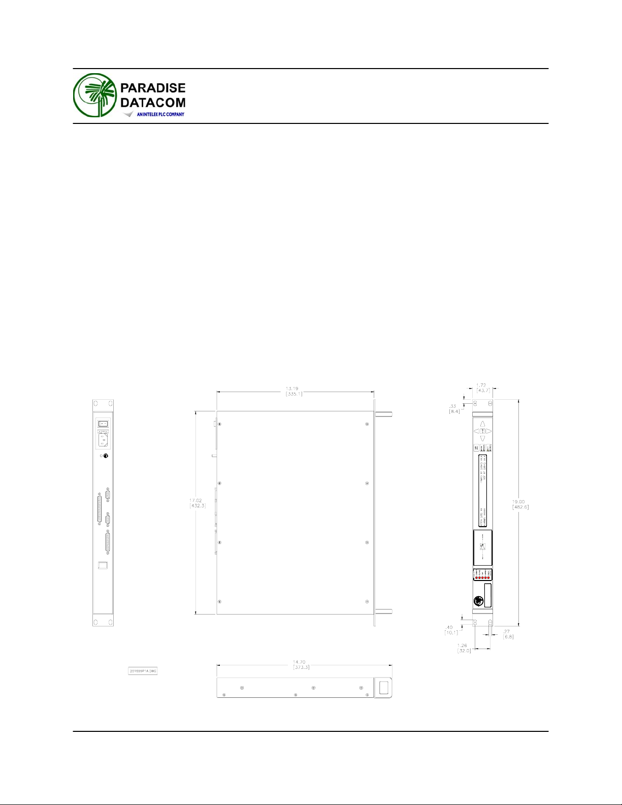
Figure 1-1: Outline Drawing of RCP2-1000 RM .................................................7
Figure 2-1: RCP2-1000 RM Rear Panel...........................................................12
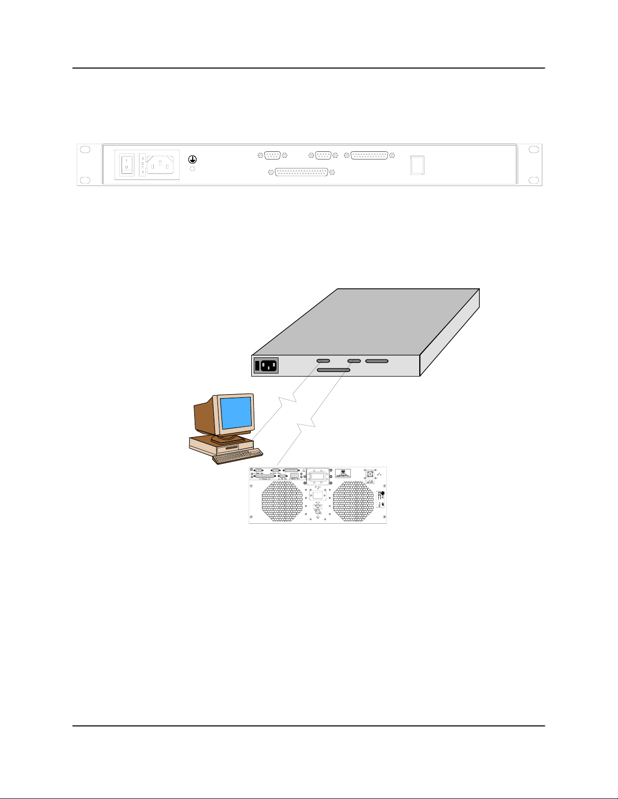
Figure 2-2: Cable Connections for RCP2-1000 RM .........................................12
Figure 2-3: Top Level Wiring Diagram..............................................................13
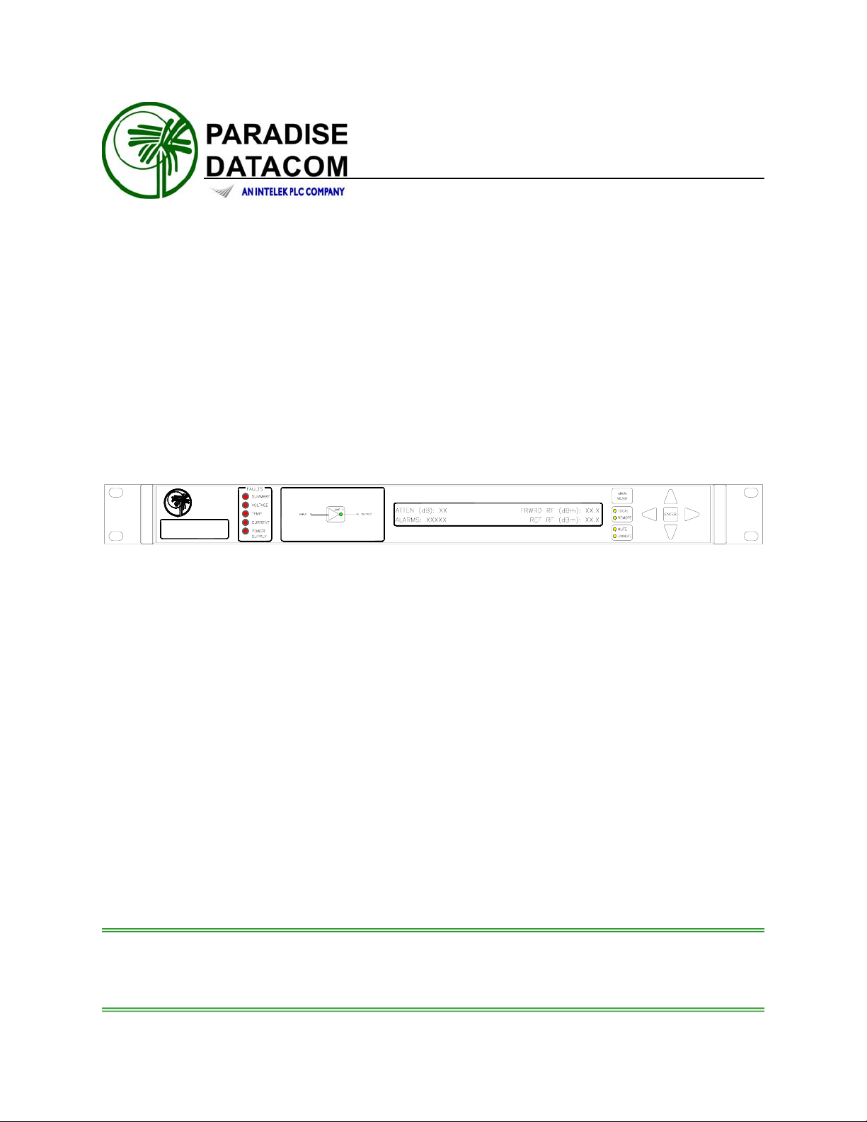
Figure 3-1: RCP2-1000 RM Front Panel...........................................................17
Figure 3-2: RCP2-1000 Menu Structure...........................................................19
Figure 3-3: RCP2-1000 SysInfo Page Structure...............................................20
Figure 4-1: Block Diagram, RCP2-1000 Digital Core Board.............................30
Figure 5-1: Basic Communication Packet.........................................................33
Figure 5-2: Header Packet................................................................................35
Figure 5-3: Data Packet....................................................................................35
Figure 5-4: Trailer Packet.................................................................................38
Figure 6-1: Connection Description Window.....................................................40
Figure 6-2: Connection Window .......................................................................40
Figure 6-3: COM3 Properties Window..............................................................41
Figure 6-4: ASCII Setup Window......................................................................41
Figure 6-5: Hyperterminal Example..................................................................42
Tables
Table 1-1: RCP2-1000 RM Specification Summary............................................9
Table 2-1: Main Serial Port Pin Out..................................................................14
Table 2-2: Local Serial Port Pin Out .................................................................15
Table 2-3: Parallel I/O Connector Pin Out ........................................................16
Table 5-1: Command Byte Values....................................................................35
Table 5-2: Data Tag Byte Values......................................................................36
Table 5-3: Error Status Bytes ...........................................................................37
6 203987 Rev A RCP2-1000 RM Remote Controller Operations Manual
Section 1: General Information
1.0 Introduction
This section provides the general information for the Paradise Datacom LLC
Redundant Control Panel for Rack Mount SSPAs. This section describes the supplied
equipment and safety precautions.
1.1 Description
The RCP2-1000 RM controller provides control of Paradise Datacom’s Rack Mount
Solid State Power Amplifiers. The RCP2-1000 RM is used for standalone or 1:1 modes
of operation. An outline drawing of the RCP2-1000 is shown in Figure 1-1.
A mimic display on the front panel indicates online and fault status of the equipment.
User interface and control is provided in three forms:
• Front Panel, Local Control
• 37-pin Parallel Control Port with Contact Closures and Opto Isolated Inputs
• Serial Data Control via RS-232 or RS-485 (2-wire)
PS1
J1
J7 PARALLEL I/O
J5 SERIAL LOCALJ4 SERIAL MAIN
J6 PROGRAM
J9 ETHERNET
DATACOM
PARADISE
RCP2-1000
CONTROLLER
SSPA REMOTE
Figure 1-1: Outline drawing, RCP2-1000-RM
RCP2-1000 RM Remote Controller Operations Manual 203987 Rev A 7

1.2 Equipment Supplied
The following equipment is supplied with each unit:
• RCP2-1000 RM Redundant System Controller (1 RU high)
• (2) IEC Line Cord Sets
• Operations Manual (203987) RCP2-1000 RM System Controller
Paradise Data can provide the following optional equipment:
• Rack Slides
• Mating cable for Rack Mount SSPA and RCP2-1000, (Part Number
L201777).
1.3 Safety Considerations
Potential safety hazards exist unless proper precautions are observed when working
with this unit. To ensure safe operation, the user must follow the information, cautions
and warnings provided in this manual as well as the warning labels placed on the unit
itself.
1.3.1 High Voltage Hazards
High Voltage for the purpose of this section is any voltage in excess of 30 volts. Voltages above this value can be hazardous and even lethal under certain circumstances.
Care should be taken when working with devices that operate at high voltage.
• All probes and tools that contact the equipment should be properly insulated
to prevent the operator from coming into contact with the voltage.
• The work area should be secure and free from non-essential items.
• Operators should never work alone on high voltage devices. There should
always be another person present in the same work area to assist in the
event of an emergency.
• Operators should be familiar with procedures to employ in the event of an
emergency, i.e. remove all power, CPR, etc.
An AC powered unit will have 115 VAC or 230 VAC entering through the AC power
connector. Caution is required when working near this connector, the AC circuit
breaker, or the internal power supply.
8 203987 Rev A RCP2-1000 RM Remote Controller Operations Manual
1.3.2 Electrical Discharge Hazards
A spark can not only create ESD reliability problems, it can also cause serious safety
hazards. The following precautions should be taken when there is a risk of electrical
discharge:
• Follow all ESD guidelines.
• Remove all flammable material and solvents from the area.
• All probes and tools that contact the equipment should be properly insulated
to prevent electrical discharge.
• The work area should be secure and clear from non-essential items.
• Operators should never work alone on high voltage devices. There should
always be another person present in the same work area to assist in the
event of an emergency.
• Operators should be familiar with procedures to employ in the event of an
emergency, i.e. remove all power, CPR, etc.
1.4 Specification Summary
Table 1-1 contains a summary of the specifications of the RCP2-1000 RM redundant
system controller.
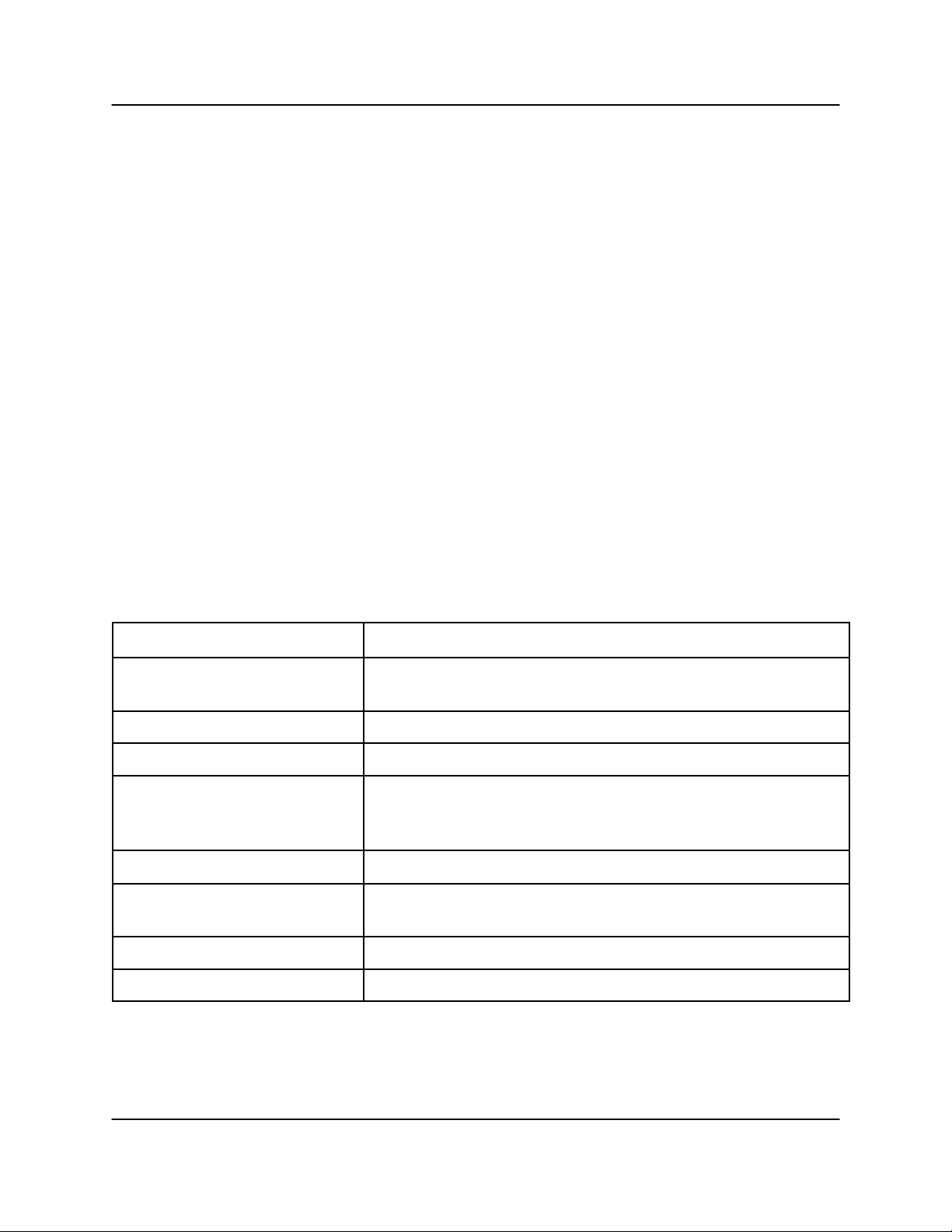
Table 1-1: RCP2-1000 RM Specification Summary
Configurations RCP2-1000 RM; 1:1 Redundant System
Switch Time Fault Detection, 20-50 msec
Total switchover, 100 msec maximum
Switch Drive 26 VDC @ 4 amps
Alarm Input Closure to Ground, (Ground = OK / Open = Fault)
Parallel I/O
Status Outputs
Control Inputs
Form C Relay Contacts (10 sets)
Contact Closure to Ground
AC Input Power 85-265 VAC, 47-63 Hz, 1 A max, > 0.93 power factor
Mechanical Dimensions 1.75 in. H x 19 in. W x 13.3 in. D [1 RU]
(89 mm H x 483 mm W x 338 mm D)
Weight 5 lb (2.3 kg)
Environmental Temperature 0 - 50 oC
RCP2-1000 RM Remote Controller Operations Manual 203987 Rev A 9

THIS PAGE LEFT INTENTIONALLY BLANK
10 203987 Rev A RCP2-1000 RM Remote Controller Operations Manual

Section 2: Installation
2.0 Introduction
This section provides information for the initial inspection, installation and external
connections for the RCP2-1000 RM redundant system controller.
2.1 Inspection
When the unit is received, an initial inspection should be completed. First, ensure that
the shipping container is not damaged. If it is, have a representative from the shipping
company present when the container is opened. Perform a visual inspection of the
equipment to make sure that all items on the packing list are enclosed. If any damage
has occurred or if items are missing, contact:
Paradise Datacom LLC
328 Innovation Blvd.
State College, PA 16803
Phone: +1 (814) 238-3450
Fax: +1 (814) 238-3829
2.2 Mounting
The RCP2-1000 RM Redundant Control Panel is designed to be mounted in a
standard EIA 9 inch equipment rack. The depth of the unit, excluding rear panel
connectors, is 13.3 inches (338 mm). The height is 1.75 inches (89 mm) or 1 rack unit.
2.3 Storage and Shipment
To protect the RCP2-1000 during storage or shipping, use high quality commercial
packing methods. Reliable commercial packing and shipping companies have facilities
and materials to adequately repack the equipment.
2.4 Prime Power Connection
An AC power connector (J1) is provided on the rear panel and provides universal AC
input by using auto-sensing power supplies. The AC input can operate over a range of
85-265 VAC, at 47-63 Hz. An On/Off switch is located adjacent to the AC input connector.
RCP2-1000 RM Remote Controller Operations Manual 203987 Rev A 11
2.5 Cable Connectors
The RCP2-1000 RM has several I/O interconnections available on the rear panel. The
controller rear panel is shown in Figure 2-1.
J1
PS1
J5 SERIAL LOCALJ4 SERIAL MAIN
J7 PARALLEL I/O
J6 PROGRAM
J9 ETHERNET
Figure 2-1: RCP2-1000 RM Rear Panel
The RCP2-1000 RM and a Rack Mount SSPA are linked together through 2-wire
twisted pair shielded cable (such as 24 AWG twisted pair telephone cable). The cable
should be connected between port J5 "Serial Local" of the RCP2-1000 and port J5
“Serial Local” of the SSPA, as shown in Figure 2-2. Figure 2-3 shows the complete top
level wiring diagram.
RCP2-1000CO
RS232 or
RS485
J4 SERIAL MAIN
J7 PARALLEL I/O
RS485
9600 Baud
To (J5) Serial Local
J5 SERIAL LOCAL
J6 PROG
J2 RF Out
Compact Outdoor SSPA
J4 M&C
Solid State Power Amplifier
C-Band
Figure 2-2: Cable connections for RCP2-1000
To achieve reliable communication over long distances an adequate line termination
(120 ohm resistor between RS485+ and RS485- lines) must be provided on both ends
of the cable. The link provides data exchange through RS485 half-duplex serial interface with 9600 Baud data rate.
Data link is peer-to-peer only; connection of a secondary SSPA or RCP2-1000 RM unit
is not possible. The RCP2-1000 RM is designed to provide remote control by using
second generation of Paradise Datacom SSPA serial protocol only. In other words, the
RCP2-1000 RM provides support only for later model SSPA units with serial numbers
above 100,000. Earlier models of SSPAs, which utilize a different style of serial
protocol, cannot be controlled by the RCP2-1000 RM.
12 203987 Rev A RCP2-1000 RM Remote Controller Operations Manual
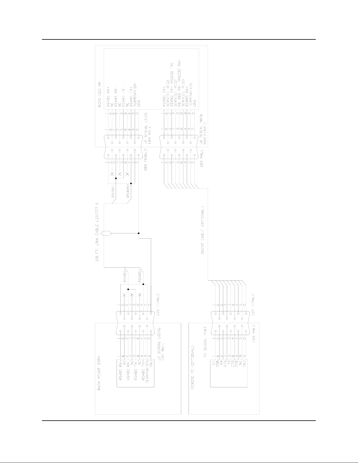
RCP2-1000 RM Remote Controller Operations Manual 203987 Rev A 13
Figure 2-3: Top Level Wiring Diagram

In order to achieve successful operation of the RCP2-1000 RM, the SSPA must be
configured with the following parameters: Baud Rate - 9600; Serial Interface - RS485;
Network Address - any. See your SSPA manual for details. Maximum cable length is
4000 feet (1.3 km).
2.5.1 Serial Port, Main (J4)
A DB9 female connector serves as primary remote control interface connector. This
interface allows the user to connect a PC to the RCP unit in order to access its advanced features as well as access a remote SSPA unit through its serial port. Interface
is re-configurable through the front panel menu, and can be used as RS-232 or RS485 interface (2 or 4 wires). The RS-485 TX and RX pairs must be twisted for maximum transmission distance. A user configurable 120-Ohm termination resistor is provided on the same connector. Table 2-1 shows the main serial port pin-out.
Table 2-1: Main Serial Port Pin Out
Pin # Function Description
1 RS485 TX+ (HPA Transmit +)
2 RS485 TX- (HPA Transmit -)/RS232 TX
3 RS485 RX+ (HPA Receive -)/RS 232 RX
4 RS485 RX- (HPA Receive +)
5 GND
6 Service Request 1 Form C relay NC contact (Closed on HPA Summary Fault)
7 Service Request Common Form C relay common contact
8 Service Request 2 Form C relay NO contact (Opened on HPA Summary Fault)
9 120 Ohm termination (must be connected to pin 4 in order to enable termination)
14 203987 Rev A RCP2-1000 RM Remote Controller Operations Manual

2.5.2 Serial Port, Local (J5)
A DB9 male connector serves as a serial interface with a remote SSPA. Interface
parameters are set by internal RCP hardware and can't be reconfigured by user. The
remote SSPA serial interface must be properly set to provide connection with the RCP
unit. Table 2-2 shows the local serial port pin-out.
Table 2-2: Local Serial Port Pin Out
Pin # Function Description
1 RS485 RX+
2 RS485 RX3 RS485 TX-
4 RS485 TX+
5 GND
6
7
8
9 120 Ohm termination (must be connected to pin 1 in order to enable termination)
2.5.3 Program Port (J6)
A DB25 male connector is used to provide on field flash re-programmability for the
RCP controller card. In order to reload controller board firmware, connect this port to
the PC Parallel port via a straight through cable.
2.5.4 Parallel I/O Connector (J7)
A DB37 Female type connector contains a series of contact closures for monitoring remote SSPA faults as well as opto-isolated inputs for controlling some of the SSPA
functions. Inputs react on the closure to ground. Minimal closure time - 50mS. Table 23 shows details of the parallel I/O pin-out.
RCP2-1000 RM Remote Controller Operations Manual 203987 Rev A 15
 Loading...