

Paradise P300 User Manual

M
E
Doc ref: p:\p300\d-wp\p300h\p3x0h.wpd (& .pdf)
Installation & Operating Handbook for
P300 Series Satellite Modems
(including P310 L-Band and
Handbook Iss ue 2. 02, dated 23 February 2004
Coveri ng software features up to and i ncludi ng V3.84
Turbo FEC options)
2003
EN 55022 - Class B
EN 55024
EN 60950
PARADIS
DATACO
Paradise Datacom Ltd. Paradise Datacom LLC
1 Wheaton Road 1012 E. Boal Avenue
Witham, Essex, CM8 3TD, England. Boalsburg, PA 16827, U.S.A.
Phone 01376 515636 (Int + 44 1376 ...). Phone 814-466-6275 (Int + 1 814...)
Fax 01376 533764 Fax 814-466-3341
http://www.paradisedata.com
IMPORTANT NOTE: THE INFORMATION AND SPECIFICATIONS CONTAINED IN
THIS DOCUMENT SUPERSEDE ALL PREVIOUSLY PUBLISHED INFORMATION
CONCERNING THI S PRODUCT
PARADI SE DATACOM maintai ns a continuing programme of product improvement
and therefore reserves the right to change specifications without notice

Table of Contents
1 EMC (ELECTROMAGNE TIC COMPATIBIL IT Y) AND SAFETY NOTICES
1.1 EMC ...................................................................... 7
1.2 SAFETY ................................................................... 7
....... 7
2 INTRODUCTION ............................................................... 9
2.1 OVERVIEW ................................................................ 9
2.2 P300 SERIES FEATURES ................................................... 10
2.3 FEATURE SUMMARY ...................................................... 11
2.4 FEATURE HIGHLIGHT ......................................................12
3 DESCRIPTION ............................................................... 16
3.1 OPERATION............................................................... 16
3.2 FAULT PHILOSOPHY ....................................................... 16
3.3 ELECTRICAL DESCRIPTION.................................................16
3.4 FRONT PANEL FEATURES .................................................. 17
3.5 REAR PANEL DESCRIPTION................................................. 18
3.6 BLOCK DIAGRAM .......................................................... 21
4 SUMMARY OF SPECIFICATIONS ............................................23
5 INSTALLATION AND CONFIGURATION ...................................... 39
5.1 UNPACKING .............................................................. 39
5.2 VISUAL INSPECTION OF EQUIPMENT ......................................... 39
5.3 INTERFACE OPTIONS ...................................................... 39
5.4 IF INTERFACE............................................................. 39
5.5 POWER UP ............................................................... 39
6 MENU SYSTEM .............................................................. 40
6.1 INTRODUCTION ........................................................... 40
<<<
THE 1 MINUTE GUIDE TO FRONT PANEL OPERATION
6.2 MENU S TRUCTURE DIAGRAM S .............................................. 41
6.2.1 Menu Structure Sheet 1 / 7 (Main: Status, Change) ........................... 42
6.2.2 Full Menu Struct ure S heet 2 / 7 (Main: Monitor, Info) .......................... 43
6.2.3 Full Menu Struct ure S heet 3 / 7 (Main: Log, Test, Setup, Action, Help) ........... 44
6.2.4 Full Menu Struct ure S heet 4 / 7 (Main, Change, User-Opt, Operation) ............ 45
6.2.5 Full Menu Struct ure S heet 5 / 7 (Change, Tx) ............................... 46
6.2.6 Full Menu Struct ure S heet 6 / 6 (Change, Rx ) ............................... 47
6.2.7 Full Menu Struct ure Sheet 7 / 7 (Change, BUC/LNB) ......................... 48
6.3 Status SCREEN DISPLAY.................................................... 49
6.4 SETUP - INITIAL CONFIGURATION MENU ..................................... 53
6.5 CHANGE MENU............................................................ 53
6.6 CHANGE, TX MENU ........................................................54
6.6.1 Change, Tx/Rx, SERVICE Menu .......................................... 54
6.6.2 Change, Tx/Rx, Service, CLOSED NETWORK .............................. 55
6.6.3 Change, Tx/Rx, BASEBAND Menu ........................................ 57
6.6.4 Change, Tx/Rx, Baseband, CONTI NUOUS Menu ............................ 57
6.6.5 Change, Tx/Rx, Baseband, DROP/ INSERT Menu ............................ 58
6.6.6 Change, Tx/Rx, Baseband, OTHER Menu ................................. 62
6.6.7 Change, Tx, CLOCKING Menu ........................................... 63
6.6.8 Change, Tx, MODULATOR Menu ......................................... 65
6.6.9 Change, Tx/Rx, Modulator, IF FREQUENCY Menu ........................... 65
6.6.10 Change, Tx/Rx, Modulator, MODULATIO N Menu ......................... 65
===
................ 40

OFFSET QPSK (OQPSK) PRIMER ............................................ 66
6.6.11 Change, Tx/Rx, Modulator, FEC Menu .................................. 66
6.6.12 Change, Tx/Rx, Mod/Demod, REED-SOLOMON M enu .................... 68
INTRODUCTIO N TO RE ED-SOLOMON ........................................ 68
6.6.13 Change, Tx/Rx, Mod/Demod, SCRAMBLER Menu ........................ 69
6.6.14 Change, Tx, Modulator, CARRIER Menu ................................ 71
6.6.15 Change, Tx, Modulator, POWER LEVEL Menu ...........................71
6.6.16 Change, Tx/ Rx, Modulator, SPECTRUM INVERT Menu ................... 72
NOTE ON BPSK SPECTRUM INVERSION ...................................... 72
6.6.17 Change, Tx, Modulator, AUPC (Software >=V 2.12) ....................... 72
6.6.18 Change, Tx, Modulator, AUPC, MODE Menu ............................ 73
6.6.19 Change, Tx, Modulator, AUPC, M A X Menu .............................. 73
6.6.20 Change, Tx, Modulator, AUPC, MIN Menu .............................. 74
6.6.21 Change, Tx, Modulator, AUPC, S LE W RATE Menu ....................... 74
6.6.22 Change, Tx, Modulator, AUPC, TARGET EB /NO Menu .................... 74
6.6.23 Change, Tx, Modulator, AUPC, TOLERA NCE Menu ...................... 74
6.6.24 Change, Tx, Modulator, AUPC, CA RRIER LOST ACTION M enu ............ 75
6.6.25 Change, Tx/Rx, ESC/AUX/BA Menu ................................... 76
6.6.26 Change, Tx / Rx, ESC/Aux/BA, DEF INE (IDR) Menu ....................... 77
6.6.27 Change, Tx/Rx, E S C/Aux/ B A, DEFINE (IBS) Menu ........................78
6.6.28 Custom IBS Overhead Allocation ...................................... 80
6.6.29 Change, Tx/Rx, ESC/Aux/BA, ASYNC ESC Menu ......................... 81
6.6.30 Change, Tx/Rx, E S C/ Aux/B A , Config Asy nc, BAUD RATE Menu ............. 82
6.6.31 Change, Tx/Rx, ESC/Aux/BA, Config As ync, FORMAT Menu ............... 82
6.6.32 Change, Tx/Rx, ESC/Aux/BA, Config As ync, SET AS REM M&C .............82
6.6.33 Change, Tx/Rx, ESC/Aux/ BA, INTERFACES Menu ....................... 83
6.6.34 Change, Tx/Rx, ESC/Aux/ BA, AUDIO LEVELS Menu ...................... 84
6.6.35 Change, Tx/Rx, ESC/Aux/BA, BACKWARD ALA RMS Menu ................ 85
6.7 CHANGE, RX MENU ........................................................ 86
NOTE ON RX=TX FUNCTION ................................................ 86
6.7.1 Change, Rx, SERVICE M enu ............................................ 87
6.7.2 Change, Rx, BASEBAND Menu .......................................... 87
6.7.3 Change, Rx, BUF F E R / CLOCKING Menu .................................. 89
6.7.4 Change, Rx, B uffer / Clocki ng, STATION CLOCK Menu ....................... 89
6.7.5 Change, Rx, B uffer / Clocki ng, RX CLOCK Menu ............................ 90
6.7.6 Change, Rx, B uffer / Clocking, BUFFER SI Z E Menu .......................... 92
6.7.7 Change, Rx, DE MOD’ Menu ............................................. 93
6.7.8 Change, Rx, Demod’, IF FREQUENCY Menu ............................... 93
6.7.9 Change, Rx, Demod’, M O DULA TION Menu ................................. 93
6.7.10 Change, Rx, Demod’ FEC Menu ...................................... 93
6.7.11 Change, Rx, Demod’ REED-SOLOMON Menu ...........................93
6.7.12 Change, Rx, Demod’ SCRAMBLER Menu .............................. 93
6.7.13 Change, Rx, Demod’ SPECTRUM INVERT Menu ........................ 93
6.7.14 Change, Rx, Demod’ SWEEP Menu ................................... 94
6.7.15 Change, Rx, Demod’ AUPC Menu ..................................... 95
6.7.16 Change, Rx, ESC/AUX/BA Menu ...................................... 95
6.7.17 Change, Rx, RX=TX Menu ........................................... 95
6.8 CHANGE, TERR-INTFC MENU ............................................... 96
6.8.1 Change, Terr-intfc, ELECTRICAL .........................................96
6.8.2 Change, Terr-intfc, CONTROL LINES ..................................... 98
6.8.3 Change, Terr-intfc, CARD SPECIFIC ...................................... 98
6.9 CHANGE, REM-M&C MENU.................................................. 99
6.9.1 Local Control TAKE AWAY / GIVE AWAY Selection .......................... 99
6.9.2 Change, Rem-M&C, CONFIGURE Menu ..................................100
6.10 CHANGE, USER-OPT MENU ................................................ 101
6.10.1 Change, User-Opt, THRES HOLDS Menu .............................. 101
6.10.2 Change, User-Opt, OP ERATION Menu ................................101
6.10.3 Change, User-Opt, Operat ion, ACTIONS Menu ......................... 102

6.10.4 Change, User-Opt, Operation, TERRESTRIAL Menu .....................103
6.10.5 Change, User-Opt, Operat ion, Terrestrial, P CM BEARER CRC Menu ....... 103
6.10.6 Change, User-Opt, Operat ion, SATELLITE Menu ........................104
6.10.7 Change, User-Opt, Operat ion, TERR/SAT Menu ........................ 105
6.10.8 Change, User-Opt, Operat ion, ALARMS Menu .......................... 106
6.10.9 Change, User-Opt, DISPLAY Menu ................................... 106
6.10.10 Change, User-Opt, AG C Out put Menu ................................. 106
6.11 CHANGE TIME/DATE MENU ................................................ 107
6.12 CHANGE, BUC/LNB MENU ................................................. 108
6.12.1 Change, BUC/LNB, TX/BUC Menu ................................... 108
6.12.2 Change, BUC/LNB, Tx/BUC, BUC TYPE Menu .........................109
6.12.3 Change, BUC/LNB , Tx/BUC, DC & REFERENCE S Menu ................. 110
6.12.4 Change, BUC/LNB, Tx/BUC, SHF FREQUENCY Menu ................... 111
6.12.5 Change, BUC/LNB, Tx/BUC, SHF POWER/UNITS Menu ................. 111
6.12.6 Change, BUC/LNB, Tx/BUC, B UC CONTROL Menu ..................... 112
6.12.7 Change, BUC/LNB, Rx/LNB Menu .................................... 113
6.12.8 Change, BUC/LNB, Rx/LNB, LNB Type Menu ...........................113
6.12.9 Change, BUC/LNB , Rx/LNB, DC & REFERENCES Menu ................. 114
6.12.10 Change, BUC/LNB, Rx/LNB, SHF FREQUENCIES Menu ................. 114
6.12.11 Change, BUC/LNB, Tune Ref M enu .................................. 115
6.13 MONITOR MENU.......................................................... 116
6.13.1 Monitor, DEMOD PERFORMANCE Menu.............................. 116
6.13.2 Monitor, TERRESTRIAL BER Menu...................................116
6.13.3 Monitor, CARRIER ID's Menu........................................117
6.13.4 Monitor, DISTANT Eb/No & BER Menu ................................117
6.13.5 Monitor, AUPC Menu............................................... 118
6.13.6 Monitor, BUC Menu................................................118
6.14 INFO MENU .............................................................. 119
6.15 LOG MENU...............................................................120
6.15.1 Log, AUTOLOG Menu .............................................. 120
6.16 TEST MENU..............................................................122
6.16.1 Test, LOOPBACKS Menu ........................................... 122
6.16.2 Test, RF & FEC Menu.............................................. 124
6.16.3 Test, PSU’S + TEMP Menu.......................................... 124
6.16.4 Test, INT' BERT Menu .............................................125
6.16.5 Test, Int' BERT, OFF/CHANNEL Menu ................................ 126
6.16.6 Test, Int' BERT, PATTERN Menu..................................... 128
6.16.7 Test, Int' BERT, MODE Menu ........................................ 128
6.16.8 Test, Int' BERT, RESULTS Menu..................................... 129
6.17 SETUP MENU ............................................................ 130
6.18 ACTION MENU ........................................................... 130
6.19 HELP MENU.............................................................. 131
6.20 SERVICE MENU ..........................................................131
6.20.1 Service, USER PARAMETERS Menu ................................. 132
6.20.2 Service, FACTORY PARAMETERS Menu..............................132
7 MENU SCREENS FOR SPECIALIST OPTIONS .............................. 133
7.1 CUSTOM FRAMING MENUS ................................................133
7.1.1 Change, Tx/Rx, Service, CUSTOM M enu .................................. 133
7.1.2 Change, Tx/Rx, Service, Custom, IBS Menu ............................... 133
7.1.3 Change, Tx/Rx, Service, Custom, IDR Menu ............................... 135
7.2 IBS/SMS OPERA TION WITH 2048KBPS CONTINUOUS DATA .................... 137
7.2.1 Change, Tx/Rx, Baseband, Continuous, 2048k G.732 Menu (IBS) .............. 137
7.3 CUSTOM IDR OPERATION WITH 2048KBPS CONTINUOUS DATA ................ 139
7.3.1 Change, Tx/Rx, Baseband, Continuous, 2048k Menu (IDR) ................... 139

8 APPLICATIO N NO T ES ...................................................... 140
8.1 DOPPLER & PLESI O CHRO NOUS BUFFERI NG................................. 140
8.2 DETERMINING CLOCKING SCHEMES AND BUFFER SIZE....................... 141
8.2.1 Clock Loop At One End: ............................................... 141
8.2.2 No Clock Loop ....................................................... 141
8.2.3 Determining Buffer Size................................................ 142
8.3 PARTIAL INSERT AND MULTIDESTINATIONAL WORKING....................... 143
8.4 CHOOSING OPTIMUM CUSTOM VALUES OF RS N&K ..........................144
8.5 NOTES ON DATA RATES & SYMBOL RATES .................................. 145
8.6 DETERMINING EXACT MAXIMUM ESC BAUD RATES ........................... 146
8.7 CLOSED NETWORK PLUS ESC .............................................147
8.7.1 Overhead Rates ...................................................... 147
8.7.2 Closed Network Plus ESC via the Custom Service menu ..................... 148
8.7.3 ESC channel with mis-match configurations ............................... 148
8.8 CROSS REFE RENCE TO SDM300 D/I & FRAMING MODES. ...................... 150
8.9 V.35 SCRAMBLERS .......................................................152
8.10 INTERWORKING DIFFERENT MANUFACTURERS EQUIPMENT ..................153
8.11 INTRODUCTION TO AUPC (AUTOMATIC UPLINK P O WER CONTROL) ............154
8.11.1 Introduction ...................................................... 154
8.11.2 Configuring AUP C for operat ion ...................................... 157
8.12 TUTORIAL ON CARRIER/NOISE & Eb/No MEASUREMENTS ..................... 159
8.12.1 Introduction ...................................................... 159
8.12.2 Derivation of Eb/No from (C+N)/N .................................... 159
8.12.3 Practical Implications of Displayed Eb/No ..............................160
8.12.4 Eb/No Explanatory Diagram ......................................... 161
8.12.5 Tables to Convert (C+N)/N to Eb/No ..................................162
9 1 FOR 1 OPERAT IO N .......................................................163
9.1 THEORY................................................................. 163
9.2 SWITCHING PHILOSOPHY .................................................163
9.3 PRACTICAL 1 FOR 1 IMPLEMENTATION...................................... 164
10 BOOT CODE OP ERATION .................................................. 165
10.1 FLASH SOFTWARE UPDATE ...............................................165
10.2 OTHER BOOT CODE OPTIONS ............................................. 166

APPENDIX A: DATA INTERF ACE INFORMATION ..............................167
GENERAL..................................................................... 167
P1440 IN RS422 MODE .......................................................... 168
P1440 IN V.35 MODE ............................................................ 169
P1440 IN RS232 MODE .......................................................... 170
P1440 IN G.703 MODE .......................................................... 171
P1440 IN X.21 MODE ............................................................ 173
MI L-STD-188-114A INTERFACE ..................................................175
P1451 EUROCOM D/ 1 `D` & `G` PLUS MULTI -S TANDARD INTERFACE .................176
APPENDIX B: MODEM CONNECTOR PINOUTS ................................ 179
REMOTE M&C (RS485/RS232) CONNECTOR ....................................... 179
Interconnecting Devices Using RS485 ........................................ 180
1 FOR 1 INTERFACE............................................................ 181
ALARMS & AGC CONNECTOR ................................................... 182
ASYNC ESC CONNECTOR ......................................................183
ESC/AUX & BACKWARD ALARMS CONNECTOR....................................185
APPENDIX C: UPGRADE INF O RMATION ....................................... 189
APPENDIX C1: MODEM CAPABILITIES & UPGRADES ................................ 190
APPENDIX C2: FEATURE SCREENS .............................................. 190
APPENDIX C3: FEATURES ON DEMO EXPIRE SOON ................................ 194
APPENDIX C4: ASYMMETRIC LOOP TIMING ........................................ 194
APPENDIX C5: UPGRADE AVAILABLE .............................................194
APPENDIX C6: FEATURES NOT AVAILABLE ........................................ 194
APPENDIX D: REMOT E M&C ................................................... 195
REMOTE M&C PROTOCOL ...................................................... 195
Summary............................................................... 195
Character Format / Baud Rate .............................................. 195
Electrical Interface .......................................................195
Mess age S tructure ....................................................... 196
Mess age Cat egories ...................................................... 197
List of A ll Remote M&C Messages ........................................... 198
APPENDIX E: CUSTOMER SPECIFIC FEATURES .............................. 201
RELAY MODE SETTING ......................................................... 201
FAULT MODE SETTING .........................................................202
UNCOMMITTED DAC OUTPUT CONTROL .........................................205
APPENDIX F : FRAMING AND DROP/INSERT OVERV IE W ...................... 207
IBS/SMS FRAMING ............................................................. 207
IBS/SMS Service Features ................................................. 207
IBS/SMS Definition ....................................................... 207
Implementation of Timeslot ID Maintenance ................................... 209
Signalling Systems Int roduct ion: CCS, CAS & RBS .............................210
Signalling Over Satellite ................................................... 210
CAS Multiframe..........................................................211
IDR FRAMING ................................................................. 213
IDR Service Features ..................................................... 213
APPENDIX G: FAULT MESSAGES AND ACTION TABLE ....................... 214

1 EMC (ELECTROMAGNE TIC COMPATIBIL IT Y) AND SAFETY NOTICES
IMPORTANT - PL EASE READ THIS INFORMA TION BEFORE INSTALLATI O N AND USE
1.1 EMC
(ELECTROMAGNETIC COMPATIBILITY)
The P300 Modem Satellite Modems have been shown to comply wit h t he followi ng standards:
Emissions: EN 55022 Class B; Limits and methods of measurement of radio interference
characterist ics of Information Technology Equi pment.
Immunity: EN 50024 Information technology equipment immunity characteristics
Extensive t esting has been performed to ensure that the unit meets these speci fications when confi gured
wi th an y or al l o f its a vai la bl e o p t ions , such a s IF band, impedance, IF synthes i ser step si ze, data rates, etc.
To ensure that the P300 Modems will maintain compliance with these standards please ensure that the
following points are observed:
1) The equipment MUST BE OPERATED WITH ITS COVER ON AT ALL TIMES. I f it is necessary
to remove the cov er for any reason, then y ou must ensure that the cover is correctly refitted before
normal operation.
2) Damage to the front panel keyboard mem brane or mechanical dam age to the chassis could
invalidate compliancy. Please contact the factory if damage occurs for advice on continued
operation.
3) For the baseband data interfaces all 'D' type connectors must have grounding fi ngers on the plug
shell to guarantee continuous shielding. The back-shells must comply to the requirements of VDE
0871 and FCC 20708, provi di ng at least 40dB of attenuat i on from 30 MHz to 1 GHz. A good quality
cable with a continuous outer shield, correctly grounded, must be u sed .
4) Connections to the trans mit and receive IF interfaces must be made with double screened coaxial
cable - for example RG223/U.
Installations which ignore these requirements will invalidate the compliancy to EMC
specifications.
1.2 SAFETY
To ensure operator safety the P300 Modems have been designed to compl y with the following safety
standard:
EN 60950 Safety of Information Technology Equipment, including electri cal business machines.
Prior to installation and operation, please ensure that the following points are observ ed:
P300H P300 Series Modem Installation and Operating Handbook Page 7

Environmental
The equipment is designed t o operat e in a stati c 19 inch rack system conforming to IEC 297-2. Operation
of the equipment in transportable installations and vehi cles equipped with the means of prov iding a stable
enviro nme nt is permissible. Operation of the equipment on vehicles, ships or aircraft without m eans of
enviro nmental conditioning may invalidate the safety compliancy. Please contact the factory for further
advice. Operation of the equipment in an environment other than t hat stated in the specifications will also
inv alidate the safety compliancy.
The equipment must not be operated in an environment in which t he unit is exposed to:
* Un-pressuri s ed altitudes greater than 2000 metres
* Extremes of temperature outside the stated operating range
* Excessive dust
* Moisture or humid atmospheres above 95% RH
* Excessive vibration
* Flammable gases
* Corrosive or explosive atmospheres
Installation
The equipm ent is classified in EN 60950 as a pluggable equipment class A for connection to the m ains
supply. A s s uch it i s provided wit h a mains inlet cord suitable for use i n the country of operation. In normal
ci rcumstance s this will be of an adequate length for installation in the rack. If the mains cable proves to be
too short then any replacement must have a si milar type fuse (if fitt ed) and be manufactured to a similar
specification. For example, look for HAR, BASEC or HOXXX-X ratings on the cable and the connector ends
ma rk ed with BS1636A (UK free plug 13 amp); BSI, VDE, NF-USE, UL, CSA, OVE, CEBEC, NEMKO,
DEMKO, SETI, IMQ, SEV and KEMA-KEUR for t he IEC 6 amp free socket. Schuko and North American
free plugs must have si milar markings.
The installati on of the equipment and the connection to the mains supply must be made in compliance to
local or national wiri ng regulati ons for a category II impulse over-voltage installation. The posit ioning of the
equipment must be such that the mains supply socket outlet for the equipment should be near the
equipment and easily accessi ble or that there should be another suitable means of disconnection from the
mains supply.
The equipment is desi gned t o operate from a TN type power supply system as specified in E N 60950. Thi s
means a system that has separate earth, li ne and neutral conductors. The equipment is not designed to
operate with an IT power sy stem which has no direct connection to earth.
CAUTION: This uni t has DOUBLE POLE / NEUTRAL FUSING.
P300H P300 Series Modem Installation and Operating Handbook Page 8

2 INTRODUCTION
2.1 OVERVIEW
This handbook describes how t o i nst all and configure the P300 Series Satellite Modems. This includes the
original P300, the P 300 Turbo, P310 L-Band and P 311 mixed L-Band/IF Modems. Where ever reference
is made to the P300 or P300 Series m odem it applies to all products unless specificall y noted .
The P300 Series may be supplied equipped with different feature sets to suit different applications. This
means that the mix of features available in any modem (such as Drop/Insert, IDR framing etc) may be
tailored to suit any user requirement, however typically they are grouped into one of four standard
configurations as follows:
P300 / P310-VSAT Features for use in VSAT applications.
P300 / P310-IBS Features for I BS/SMS use (or thin route IDR below T1) services .
P300 / P310-IDR Features for IBS/SM S AND IDR services (IDR at T1 or great er).
P300 / P310-TCM Features for use in TCM, TCM/IDR, IBS/ SMS and standard IDR services.
The table on page 11 summ arises the different features, and which features are available in the four
standard configurations.
The P300 Series Modems are designed for operation i n a typical ground stat ion environment, providing a
data link bet ween geographically distant sites via satellite. Like its predecessors, it is physically small, light,
and of rugged construction, allowing it also to be used in mobile and fly away terminals.
The P300 Series provides a data port on the terrestrial side which provides RS422, V.35, and RS232
software selectable interfaces on both 25 pin EIA 530 and 37 pin RS449 connectors. Optional G.703
interfaces provide either a T1 or E1 (1544kbps or 2048kbps) G.703 interface in addition t o the standard
three interfaces. The modem couples into the ground stati on up / down converter chains on t he RF side
at either 70MHz or, if the Wideband IF feature is available (standard on P300-IBS and above), 140MHz.
The status of a unit is available externally on `form c` relay outputs designed to connect to station
monitoring system. The modems also provides a complete remote Monitor & Control (M&C) port, allowing
the status to be remotely monitored and the unit controlled or the configuration changed.
If Async ESC feature is available (standard on P300-IBS and above) the modem can provide an
asynchronous E ngineering Serv ice Channel carried across the sat ellit e link as an overhead added to the
main data channel. The ESC channel can be internally linked to t he remote M&C port, allowing any modem
to be monit ored or controlled from the distant end of the satellite link. In additi on, external equipment (such
as radio trans cei v ers) i f coupled int o the remote M &C port may also be accessed remotely over the satellite
link.
Higher speci fied P 300 modems additionally feature many advanced functi ons including variable code rate
Reed-Solomon, the ultimate in T1/E1 Drop/Insert functionality, separate ESC & Aux channels with
independent electri cal interface s election, a bui lt i n Bi t Error Rate Tester (BERT) which can run continuously
through the ESC or A ux channels loggi ng results in the traffi c log, plus a Closed Net P lus ESC (`minimum
overhead`) mode in whi ch the overhead varies from <0.5% to whatever is required to support virtually any
async ESC channel requirements.
To provide as simple as possible software upgrade facility, the embedded monitor & control softw are can
be changed without openi ng the product. Unlike ot her equipment which holds the embedded M&C software
in E P ROMs (requiring replacement EPROMs to be shipped, changed & returned), the P300 Modem M&C
soft ware is downloaded in to FLASH memory via a rear panel serial port from a PC. A process which
requires no tools and i s completed in 30 minutes. F or operat ors requiring the lates t features or upgrades,
the most recent release of the internal M&C software is available on our Web site
(http://www.paradisedata.com) for free download.
P300H P300 Series Modem Installation and Operating Handbook Page 9

2.2 P 300 S ERIES FEATURES
As t his handbook cov ers the full feature set of the P300 Modem, some of the text will not be applicable to
modem s equipped with only a subset of the possibly functionality. In the text where it describes features
which are optional it uses phrases like:
Requires Drop/Insert feature (standard on P300 IBS and above)
Throughout the tex t the des cript i on of the feature (“Drop/Insert”) is consistent, and wherever it is referenced
it also states which of the four standard configurations this feature becomes available as standard. I n the
above example the Drop/Insert feature is standard on the P300-IBS confi guration, and all models above,
i.e. the P300-IBS, P 300-IDR and the P300-TCM.
The P300 Series has been designed to make field upgrades as eas y as possible, and many features may
be added by front panel entry of a “Feature Code” which can be issued by Paradise Datacom. Some
Options however may require extra hardware to be added (eg extra boards or just IC’s) but this is easily
performed by a competent technician. The table on the following page indicates which features may be
added from the front panel, and which require the addition of extra hardware.
It might appear that the words `Feature` and `Option` are used interchangeably. In practice however we
have attempted to use `Opt ions` to refer to functions which always require hardware to be fitted, whereas
we us e ` F ea t u r es` to r ef er t o fu n ct ions w hi ch may be software enabled without ex tra hardware being fitt ed.
For ex ample we refer to both IDR and G.703 Options (as these each require an extra board t o be fitted),
whereas we refer to Drop/Insert and Reed-Solomon Features (as these are software enabled features
wit hin the basic modem hardware).
If you are new to the equipment it is worth confirming what features and options are available in the
equipment you have. If it is one of the four standard configurations then a copy of the next page might be
useful as you w ork through the manual to prevent y ou hav i ng t o refer back to it. If it is a user defined feature
set, then refer to A ppendix C2 which explains how to determine the features available on any P300 Series
modem.
When specifying the feature set of a modem , an Excel spreadsheet which mimics the following table is
avai lable on request. The sp reads heet directly calculates the cost of the varying features you may specify,
and when printed may be used to order modems. It also directly generates an order code for any user
feature set you may specify and lists any warnings with the feature set you have specified.
P300H P300 Series Modem Installation and Operating Handbook Page 10
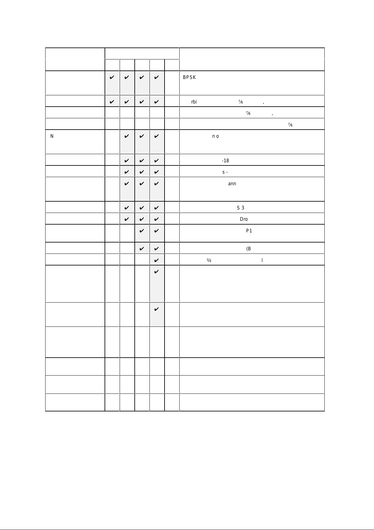
2.3 F E ATURE SUMMARY
Feature
* means h/w option
Base Modem
Viterbi FEC *
Sequential FEC * Sequential FEC, rate ½, ¾ &
Turbo FEC (TPC) * Turbo FEC, various preset code rates (inc ½, ¾,
INTELSAT
Reed-Solom on (switching to 225, 205, 10 or 219, 201, 9 with 4/8 deep
Wideband IF
High Data Rates
Async ESC
IBS/SMS
Drop/Insert
IDR *
P300 Series Configuration
VSAT IBS IDR TCM USER
UUUU
UUUU
UUU
UUU
UUU
UUU
UUU
UUU
UU
Description
BPSK/QPSK/OQPSK, 4.8kbps to 512 kbps modem
RS422 / V.35 / RS232 interface with 25 & 37 pin connectors
50MHz - 90MHz IF interface with 100Hz resolution
Viterbi FEC, rate ½, ¾, & f in BPSK, QPSK and OQPSK
f
in BPSK, QPSK, OQPSK
f
& 0.789)
Reed-Solom on outer FEC, with n, k, t = 126, 112, 7
interleaving as required for IDR & TCM/IDR)
Wideband 50MHz-180 MHz IF (instead of 50MHz - 90MHz)
Data rates 512kbps - 5Mbps in addition to Base Modem rates
Variable rate ESC channel for Closed Net plus ESC operation
High rate IBS/SMS ESC (with IBS/SMS feature)
Async access to IDR 8k sync ESC channel (with IDR option)
IBS/SMS framing (to IESS 309)
Normal T1/E1 linear order Drop/Insert
IDR operation (to IESS 308), P1348 Emulation &
32/64kbps Aux data in place of one/both IDR audio ESC
PRBS Tester
8PSK/TCM
Extended D/I
Custom Features
Monitor/AGC * Demod Rx carrier signal level monitor
AUPC Automatic Uplink Power Control
1544kbps G.703 * 1544kbps G.703 interface in addition to RS422 / V.35 / RS232
2048kbps G.703 * 2048kbps G.703 interface in addition to RS422 / V.35 / RS232
UU
U
U
U
Internal Bit Error Rate Tester (BERT, overhead modes only)
8PSK with b rate Trellis Code Modulation (to IESS 310)
Independent timeslot re-ordering on Tx & Rx
Signall ing (CAS for E1 & RBS for T1)
Rx Partial Insert for multi-destinatio nal working
Timeslot ID main tenance for N=1 to 31 with IBS/SMS or Closed
Net plus ESC operation
Arbitrary `n` & `k` for Reed-Solomon (with RS fe ature)
Custom & Min O/H modes (with IBS/SMS o r IDR options)
Custom allocation of IBS o/h between ESC / Aux channels
0-10V Analog output of carrier signal level, Eb/No, or Rx offset
frequency (in addition to normal AGC output)
Constellation monitor port
(requires Async ESC feature to operate)
interface (software selectable)
interface (software selectable)
Options marked wi th an as teri s k wi ll require boards or single IC’s to be added to the unit in order to add the
option at a later dat e. Feat ures w i thout an ast eri sk can be added by entering a “Feature Code” int o the front
panel of the equipment.
P300H P300 Series Modem Installation and Operating Handbook Page 11

2.4 F E ATURE HIGHLIGHT
This list highlights s ome of the notable features about t he P300 Series M odems:
All P300 Series Mod em s (ie base modem features)
U
Variable data rate in 1 bps steps w ith fast acquisition even at low data rates
U
BPSK, QPSK, and Offset QPSK (OQPSK)
U
Viterbi FEC (to IESS 308/309), rate ½, 3/4 & 7/ 8 in BPSK, QPSK and OQPSK.
U
100Hz IF resolution
U
RS422, V.35, and RS232 DCE interface on both EIA 530 25 pin and RS449 37 pi n connect ors.
U
Can accommodate Viterbi & Sequential FEC simultaneously
U
Built in 1-FOR-1 Redundancy Controller (requires only cables, passive IF splitter/combiner &
second modem for complete 1:1 in just 2U)
U
0-99ms Doppler/plesiochronous buffer
U
Full re mote M& C
U
1000 event t raffic log, wi t h facility to continuously log circuit performance at regular intervals (logs
average & w o rs t case Eb/No and/or user BE R)
U
`In The Rack` upload of revis ed internal software
U
25dB Tx IF level control in 0.1dB steps
U
Band limited IF input capable of operati ng with high composit e power (ie IF input not `wide open`
and affected by out of band signals)
U
1PPM internal frequency & clock reference, with external station clock input & options for higher
stability internal references
U
CCITT & INT ELSAT V.35 scramblers for closed network operation, with additional two modes for
compatibilit y with F DC and Linkabit proprietary patterns .
U
Deferred alarm at user set serv ice limits (individual Eb/ No, BER & Buffer slip thres holds)
U
Frequency locked clock loops (ie not phase locked) immune to clock hits caused by equipment
such as routers
U
Comprehensive monitoring and status display, with explicit fault descriptions of most significant
fault for Tx & Rx paths
U
P500 1-FOR-N Switch avai lable allowing mixed in terfaces within 1:N system
U
Supported by Alphawav e CAM multi-product remote M&C sy stem which can provide centralised
log gathering on a PC (including logged circuit performance figures, eg E b/No every 10 mins)
U
Soft ware includes two `User Variables` to accomm odate custom user requirements (such as
special alarm handling), allowing s pecial user requested features to be added w hilst sti ll keeping
common software
U
Clear displ ay, intuitive menus with `Normal` selections & effi cient user interface w ith full keyboard
U
Tx or Rx paths may be selected as `Off`, muting appropriate alarms in Tx or Rx only appli cat ions
U
Three form `C` relays provi d ing prompt Tx/Rx Traffic faults, as well as a prompt unit (equipment)
fault and a deferred alarm.
P300H P300 Series Modem Installation and Operating Handbook Page 12

P300 / P310 -IBS Ad d i tional Features
U
INTELSA T Reed-Solomon Feature
A fully INTELSA T compliant Reed-Solomon Codec providing
i
Automatic selection of appropriate INTELSAT values of `n, k & t` and interleaving depth for
data ra te & service selected (n, k, t = 126, 112, 7 by default, sw itching to 225, 205, 10 or 219,
201, 9 wi t h 4/8 deep interleaving as required for IDR & TCM/IDR)
i
Provides improved low Eb/No performance in framed mode due to use of extended threshold
frame sync algorithms
i
Enhanced capabilities wit h t he `Custom Features` feature (see later)
U
Wideband IF Feature
The extension of the 50MHz - 90MHz IF range up to 50MHz - 180MHz
U
High Date Rate Feature
The extension of the data rate range to include rates above 512kbps up to 5.0Mbps (depending
on modulation and FEC modes)
U
A sync ESC Feature
The addition of a hi gh rate async ESC channel, which may be internally linked to the M&C port to
provide control of distant end equipment (in all overhead modes) without additional cabling. The
Asy nc E S C feature provides as follows:
i
Support for any as ync ES C r ate i n Clo s e d Ne t P l us ESC mode, providi ng a scalable overhead
which adds the minimum possible overhead to the satellite data to provide the baud rate
selected (adding from <1% to 100% ov erhead). Closed Net Plus ESC mode also provides an
optional backward alarm facility and abov e 32kbps a synchronous scrambler to replace the
normal error multiplyi ng V.35 self synchroni s ing scrambler.
i
A high rate async ESC channel in IBS/SMS overhead, achieving 2400 Baud with a 64kbps
carrier (requires IBS/S MS feature, standard on P 300-IBS and above)
i
Async access to the IDR 8kbps synchronous ESC channel. (requires IDR option, s tandard on
P300-IDR and above)
i
Software selectable RS232, RS485 or RS422 interface.
U
IBS/SMS Feature
Satellite Framing i n accordance w ith IBS (to IESS 309) and SMS (EESS 501), including:
i
User assi gned Tx , and corresponding Rx display of, Stat ion ID, Channel ID & S pare ID within
SMS overhead to aid carri er identification.
i
A high rate async ESC channel in IBS/SMS overhead (see Async ESC above)
U
Drop/I nsert F eatu re
The most sophisticated Drop/Insert functions of any satellite modem whilst still maintaining
simplicit y of configuration and operation. The Drop/Insert feat ure provides:
i
1544 kbps T1-D4 & T1-ESF and 2048 kbps G.732 operation
i
Arbitrary & independent t imeslot selection for Drop & Ins ert
i
Full support for CRC-4 in G.732 mode and CRC-6 in T1-ESF mode
i
Terrestrial error monitoring based on Frame Alignment Words (FAW) or CRC
i
G.732 `E bit ` proces sing, allowing the display of the outbound terrestrial error rate
i
Loopthrough or generation of local bearer onto which to insert the Rx data from any normal
clock source (eg statio n clock, clock from satellite, internal clock)
i
Automatic generat ion of backup bearer so Rx traffi c is not lost i f Drop bearer into Tx fai ls and
bearer is looped through to the Insert mux to pick up Rx data
i
Timeslot ID maintenance even with Closed Net P lus ESC carriers
i
Enhanced features with the Extended D/I Feat ure (see later)
P300H P300 Series Modem Installation and Operating Handbook Page 13

P300 / P310 -IDR Additional Features
U
IDR Option
Satellite Framing in accordance with the IDR specification (to IESS 308), i ncludi ng:
i
Standard IDR framing with 2 x 32 kbps ADPCM audio ESC, a sy nchronous 8kbps ESC data
channel, and four backward alarms
i
Enhanced features with the ‘Custom Features’ feature (see later)
i
Independent ES C & A ux Ports to replace the shared ESC/A ux port of the base modem. The
ESC and Aux ports are acti ve in all framed modes. They prov ide the following features::
'
ESC Port provides a front panel selectable RS232, RS422, or RS485 interface. In IDR
Mode it provides e ither a synchronous interface to the 8kbps I DR ESC channel, or (if the
Async ESC feature is available, standard on P300-IBS and above) an async inter f ac e
supporting up to 4800 or 9600 Baud eg for distant end M&C vi a the IDR overhead. Thi s
same ES C p o rt, although part of the IDR option, in Closed net Plus ESC o r IBS/SMS
modes pr ovides a high rate asynchronous ESC interface (eg 2400 Baud at 64kbps in
standard I BS/SMS mode, any Baud rate for Closed Net Plus ESC). A gain typically used
for distant end M&C via the overhead.
'
Aux Port provides a front panel selectable RS232 and RS422 int erface. In IDR Mode it
provi des synchronous 32 or 64 kbps channel in place of one or both the 32kbps ADPCM
ESC audio channels. I n I BS/SMS & Minimum Overhead modes it prov ide a synchronous
por t which can be configured to use from 1/32 to 21/32 of the IBS/SMS overhead (eg for
internal or ex ternal BER testing). When set t o 1/32 and used asynchronously it prov ides
the INTELSA T compliant Low Rate ESC channel.
U
PRBS tester feature
The internal Pseudo Random Binary Sequence (PRB S ) B it Error Rate Tester (B E RT) offers the
following features:
i
PRBS can pass through the main data channel, or the ESC or Aux channels of the overhead
in parallel with the main dat a channel i n any mode where overhead is added.
i
BE RT results can be logged in the traffic log at user set intervals, providing cont inuous traffic
quality monitori ng and recordi ng when operat i ng through t he overhead in parallel with the main
data.
i
Compatible with pat terns used by test equipment such as the Firebird etc.
P300H P300 Series Modem Installation and Operating Handbook Page 14

P300 / P310 -TCM Additional Features
U
8PSK with b rate TCM (50% bandwidth of QPSK ½ rate Viterbi)
U
Extended D/I Feature
The extended Drop/Insert provides significant extra features compared to the basic Drop/Insert
feature set:
i
Arbitrary & independent timeslot re-ordering for Drop & Insert
i
Full support for G.732 Channel Associ ated Signalling (CAS) over IBS/S MS links
i
T1-D4 & T1-ESF Robbed Bit Signalling (RBS) maintenance over IBS/ S MS links
i
Maintenance of timeslot ID for N=1 to 31 inclusive when using any framing (norm ally only
N=1 , 2, 3 , 4, 5, 6, 8, 10, 12, 15, 16, 20, 24 are maintained for IBS/SMS and there is no ID
maintenance for IDR)
i
Insert ion of only partial received data (for multi-destinat ional working)
U
`Custom Features` Featu r e
With respect to the Reed-Solomon, the Custom Features prov ides:
i
Codeword length (`n`) variable from 60 to 255
i
Error correct bytes (`t`) variable from 2 to 20 in st eps of two
i
Selectable 4 and 8 depth interleav ing
With respect to the Framing, the Custom Features provides:
i
Custom IDR Modes including 16kbps ADPCM mode providing all normal IDR facilities in a
64kbps overhead, or all normal IDR faciliti es plus a 32kbps Aux channel i n the normal 96kbps
overhead (which allows an internal or external PRBS test to run in parallel with the traffic to
monitor the service quality). The overhead can also be reduced to provide reduced IDR
facilities with 64kbps or 32kbps overheads.
i
Custom IBS/ SM S modes i ncluding faci liti es for multidestinational IBS carriers wit h 4 backw ard
alarms, and Mini mum Overhead modes (a more configurable vers ion of Closed Net Plus ESC)
wh ere the overhead varies from the standard 16/15 (6.7%). In minimum overhead mode the
user sets the required ESC Baud rate and the overhead is scaled to the minimum value to
provide the service required. For example 2048kbps wi th 9600 B aud E S C in overhead of <1%,
or 64kbps data with ESC rates up to 38. 4kB aud
With respect to the ESC Channels
i
Ful l user allocation of the overhead between ESC and Aux channels in IBS/SMS modes,
pro viding user control over the relative rates of the async ESC channel and the sync Aux
channel.
Turbo Product Code Forward Error Correction (TPC FEC))
U
Turbo codec for bandwidth and power efficiency
U
Software can support up t o 31 preset code rates (initial rates i ncludes rat e ½ , ¾, f & 0.789)
U
¾ Rate for compatibility with industry De-Facto Turbo.
U
½, ¾ & f Rat e al lo w s wit c h to Tur bo & b e t t e r ma rg in / quali ty of serv ice than Vi terbi in same space
segment (eg fixed capacity on long lease)
U
0.789 rate prov ides optimised performance near 3/4 rate for newer circuits.
Monitor / AGC Option
U
Moni t or and display of Rx carrier level
U
Rear panel PSK constellation monitor point
U
An uncommitted 0-10V DC analogue output, set from the front panel to output AGC/ Signal level
(for antenna pointing / tracking), Eb/ No, user BER or any other parameter available internally.
A u to Up link Power Control (AUPC) Feature
U
AUPC via async ESC ch annel on IBS/SMS, IDR and Closed Net Plus ESC carriers (ie overheads
down to <1%).
U
Automatically Interleaves AUP C w ith dist ant end remote M&C (if active) on ESC channel.
U
Monitor only option for di stant end Eb/No & BE R monitoring without power control.
U
Adds optional automatic regular logging of AUPC delta power and distant end Eb/No.
U
Uni-direct ional, bi-directional and broadcast (Tx only / self monitor) modes.
P300H P300 Series Modem Installation and Operating Handbook Page 15

3 DESCRIPTION
3.1 OPERATION
The P300 Series modem are fully software controlled and wit h the ex ception of the optional G.703 interface
option there are no links or sw itches used to configure t he unit. This enables all control and configurati on
to b e p er fo rmed either locally from the front panel, or by remote M&C. Local control is by front panel
keyboard, and a large, eas y to read, 80 character LCD display, with clear, intuitive menus for configuration
and control. All the set-up parameters are stored in non-volatile mem ory which will retain data for a
minimum of 3 years, with no power applied. The receive and transmit functions of the Modem are
independent, so that they may be operated at a different data rat es, IF frequencies, or different services if
required.
Like al l Pa rad ise Datacom products, the P300 Series includes a traffic log which stores the last 1000
events , s ui tably ti me-stamped. It can automatically add s ev eral measured parameters to the log at operator
set intervals, including average & w orst case Eb/No, average & worst case estimated user BER, average
& worst case estimated uncorrected BER, and the buffer fill state. The l ogged performance m onitoring
allows inves tigation int o cus t omer reports of poor link performance, and can provide a useful correlation
against weather conditions, etc.
3.2 FAULT PHILOSOPHY
Faults are split into two categories:
a) UNIT FAULTS: Equipment failures (such as a synthesiser lock failure).
b) TRAFFIC FAULTS: Data path failures, (such as a lack of input clock).
A full description of every detected fault, its category (unit or traffic), and the corresponding action taken
is pr ovided in Appendix G - Faul t Messages and Action Table. The response of the front panel LED
indicat ors and external fault relays respond is described in the following secti ons.
3.3 ELECTRICAL DESCRIPTION
The P300 modem com prises of a single main modem Printed Circuit Board (PCB) with four optional
additional boards:
'
Optional G.703 interface (two different boards for T1 or E1 operation).
'
Optional I DR ESC board which prov ides for all the IDR ESC requirements
'
Optional Monitor / AGC board which provides a user scalable AGC output and a constell ation
monitor point.
'
Optional Turbo FEC daughtercard
For the P310, an L-Band daught erboard is also fi t ted internally abov e t he main modem board, and further
three internal options are possi ble:
'
Reference oscillator options (several of varying stabilities)
'
An internal 100W PSU to provide a DC feed to an external BUC
'
An optional FSK com munications board, to enable a m odem and BUC to bo operated from the
modem front panel (and to provi de closed loop power control to the BUC flange).
P300H P300 Series Modem Installation and Operating Handbook Page 16
Status LEDs
Green:
Modem itself OK
)fic fault (external to modem)
)fic fault (external to modem)
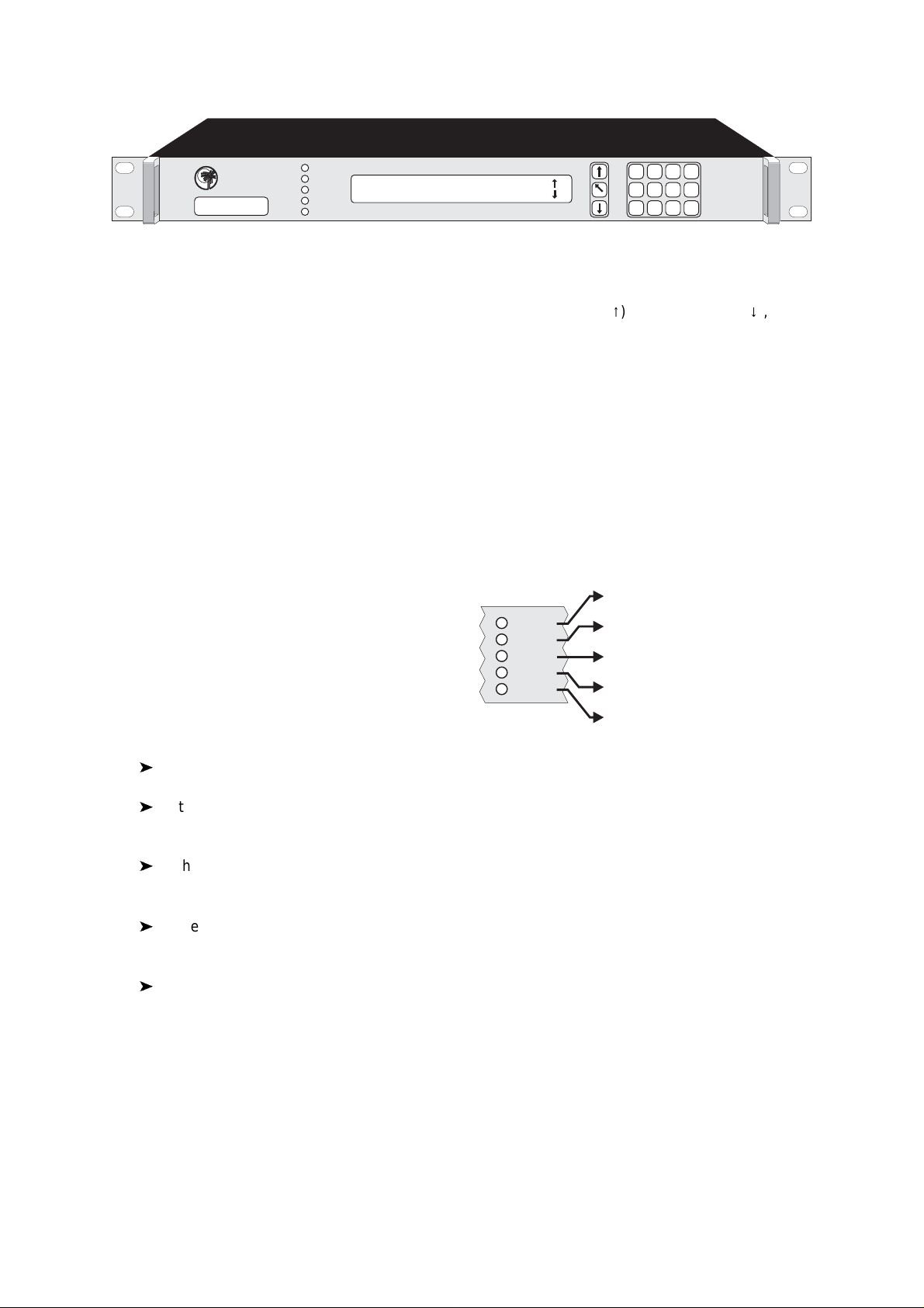
3.4 F RONT P ANEL FEATURES
PAR AD ISE
DATACOM
P300 Series
Satellite Modem
STATUS
RX OK
TX OK
TEST
STANDBY
Tx path OK for 3.7days
Rx path OK for 2.1days BER < 1E-12
YES /
ENTER
8
7
4
1 2
9
5 6
3
NO /
PREV
MAIN
0
P300 Modem front panel view
Keyboard
The keyboard is of t he membrane type (an integral part of t he front panel) whi ch provide a direct t a ctile feel.
8
There are 15 keys i n tota l - number keys in t he range 0 to 9, an up arrow key (
), down arrow key (9), MAIN
key, YES/ENTER key , and NO/PREV key.
LCD display
This backlit dis play provides 2 lines of 40 characters each and is hi ghly legible even in condi tions of high
ambient light. The LCD provides detailed information about the status and configuration of the unit, and
when appropriat e, prompts t he user to enter data via the keypad.
Monitor port
The circular m onitor port available on the front panel of previous products has been moved to the rear
panel and is now combined onto the Async ESC connector (a `D` t ype connector instead of t he difficult to
obtain 8 pin `din` audio t ype connector). See the description of the “Async ESC connector” under the rear
panel descripti on which starts on t he next page.
LED Indicators
Five LEDs on the front panel provide summary fault
information, so that even when the LCD is unavailable
for status display (such as when the operator is
rec o nf iguring the unit, and a m enu is displayed), the
cur r en t status can always be assessed. If any of the
LED's indicate a fault, press MAIN, then select Status
to display the current fault conditi on.
STATUS
RX OK
TX OK
TEST
STANDBY
Red:
Modem internal fault
Green:
Rx traffic OK
Off:
Rx traffic fault (external to modem
Green:
Tx traffic OK
Off:
Tx traffic fault (external to modem
Off:
Normal
Amber:
Loopback or Test mode active
Off:
Normal (Tx carrier on)
Amber:
Tx carrier off or Standby of 1:1
'
In normal operation there should be three GREEN LED's showing.
'
If the St a tus is RED, the unit has failed due to internal or possibly external conditi ons. Refer to
the text on the LCD Status screen and rectify if possible.
'
If the TX OK or RX OK LED's are off, then t he Tx or Rx traffic has failed due to an external fault,
again refer to the t ext on the LCD Status screen and rectify if possible.
'
If the TEST LED i s AMBER, a test mode or loopback is active, press MAIN, and select Test to
query or change the test setti ngs.
'
If the STANDBY LED is Amber, the Tx carri er i s off. It may be intentionally switched off, or it may
be muted due to either a fault, an external mute signal, or if in a 1-FOR-1 redundant pair it may be
the standby unit.
P300H P300 Series Modem Installation and Operating Handbook Page 17

3.5 RE AR PANEL DESCRIPTION
At the rear of unit are all of the connectors necessary for the user to interface the Modem to the outside
world; IF input and output to frequency conversion equipment, terrestrial data connection, station clock,
alarms & AGC output, remote M& C, AC power and so on.
MULTI STANDARD INTERFACE
P1440A
This text so coreldraw doesn’t crash on export !
100-240Vac
0.3-0.1A
50/60Hz
PARADISE DATACOM
S/N
1097
1 FOR 1 ALARMS & AGC
1998
ASYNC ESC
ESC, AUX &
BACKWARD
ALARMS
Tx IFRx IFSTATION CLOCK REMOTE M&C
E1
75R
IN OUT
P300 Modem rear panel view (IDR & G.703 options fitted)
From left to right, the rear panel connectors are:
IEC mains power connector/voltage selector/fuse
The Modem is desi gned to operate from a mains AC supply of 100-240V (-15% + 10%, ie 85V to 264V at
the connector). The IE C connector i ncorporates tw o fuses, independently fusi ng both live and neutral lines.
Acc ess to the f uses are provided by a slide out t ray. Both fuses are standard 20 mm type, rated 2A, of the
slo w-bl ow (time delay) type. ALW AYS REPLACE THE FUSE W ITH ONE O F THE SAME TYPE AND
RATING.
Chassis ground stud
This is an M4 stud for connecting a safety earth conductor di rect ly to the chassi s of the unit.
Fan
The fan may be selected to be temperature controlled or permanently active (ie the fact that it is not running
does not indi cat e i t has failed). Us e the t est menu to display the internal unit temperature if in doubt, the fan
E
comes on at 26
C and off at 24EC.
Station Clock
S
This connector i s a 75
BNC fema l e wh ich accepts a 1 -10MHz s ignal, either a square w ave of >1V p/p (eg
a G.703 para 10 `synchronising clock`) or a sinusoid at a power level of 0dBm or greater. An alternative
Stati on Clock signal at RS422 interface levels can be applied to the A sync ESC connector. Either signal
can be u sed by the modem as a reference for the receive out put clock (the St ation Clock does not have
to be the same r ate as the data as an internal PLL converts between rates). In addition i f the Rx Clocking
is set to use t he “Station Clock” and the Tx Clocking is set to “Rx”, then the Station Clock also sources the
int ernally generated Tx Clock (Tx & Rx data rates are independent). Finally, if a 10M Hz s ignal is applied,
this signal may also be used in place of the internal reference for the Tx and Rx IF synt hesisers.
1:1 Redundancy connector
The Modem has a built-in 1 for 1 redundancy controller which connects to the corresponding port of
another Modem via this 9 pin m al e 'D' type connector. A com pl ete 1:1 redundancy system requires only
two modems, a 1: 1 control cable (on this port), a data split (`Y`) cable, and passive s pli tters/combiners for
the IF port s (or s plit ters /combiners already pres ent i n t he sy s tem). Connection details are given in A ppendix
B, and an ov erview of 1 for 1 operati on is provided in section 9 starting on page 163.
Remote M&C co n n ector
This is a 9 pin female 'D' type connector whose pinout and interface levels are `SA-bus` compliant. The
Modem can be set to operate with either Paradise/FDC or SA-bus protocols. The electrical in t erface can
be selected between RS232 (for direct to PC applications) & RS485 (for mul tidrop applications). The
Remote M&C port may be internally linked (ie no cable s) to the Async ESC port for over the satellit e distant
end Remote M&C control. Pinout details are i n A ppendix B .
P300H P300 Series Modem Installation and Operating Handbook Page 18

Rx IF input
S
This connecto r is a BNC female and can be used as either a 50
of the desired carrier at the input of the modem is from -60dBm to -30dBm (P310: -70dBm to -20dBm). A
level of -45dBm is recommended. The maximum composite power level that should be applied to this port
is 30dB above the desired carrier, up to a maximum of 0dBm (P310: Com posite +35dBc to max of 10dBm).
Al arms and AGC connector
This is a 15 pin male 'D' type connector that provides access to the three form `C' relay contacts that
indicate alarm conditions. Also provided on this port if the Monitor/AGC option is fitted is an uncommitted
analog output which by default provides an AGC output, but which may be selected via the front panel to
pro vide other user requested signals (eg Eb/No, Rx IF offset frequency, or other uses implemented as
required). The alarm relays have t he followi ng definitions:
Unit Fault:A unit fault ex ists, i.e. an equipment failure.
Traffic Prompt: A Tx or Rx traffic faul t exists.
Deferred alarm: One of the following conditions exists:
The receive BER is greater than the user defined threshold.
The receive Eb/No is lower than the us er defined threshold.
Buffer slips are more frequent than the user set threshold.
A Backward alarm is being received from either the satellite or terrestrial
ports.
or 75S input. The allowable signal lev el
Full pinout detai ls are provided in Appendix B . The alarm relay functions can be changed, See `Relay
Mode` in appendix E .
A sync ESC connector
This 15 pin `D` female connector provides a superset of the features found previously on the front panel
circular 8 pin `din` connector. It includes an RS232 serial port for the loading or revised internal software
from a PC or the printing of the uni t s t raffic log to a serial printer / PC terminal emulator. If the Monitor/AGC
option i s fi tt ed i t prov i des I , Q, and symbol clock outputs to monitor the receive constellation (in order to view
received signal quality on an oscilloscope). When the IDR option IS NOT fitted, it provides an
RS232/RS422/RS 485 asynchronous port for either the high rate Async ESC facility (for IBS/SMS or Closed
Net Plus ESC services) or the IBS/SMS `low rate INTELSAT oversampled ESC facility` (which is configured
as the Aux data channel on the modem). When the IDR opti on IS fitted, separate ports for the ESC and Aux
channels on the IDR card are acti v at ed, and E S C/ Aux access on this async port is disabled. Finally, this
connector also provi des t he port for an RS422 compatible Station Clock (see the Station Clock paragraph
on the previous page).
Tx IF output
S
This connector is a BNC female and can be used as either a 50
can be vari ed from 0dBm to -25dBm on 0.1dB steps from the front panel (P310: -5dBm to -30dBm).
ESC & Aux connector
This connector is fi tted as part of the IDR option (Standard on P300-IDR & P300-TCM ), it provides access
to:
'
Four ba ckwa rd al arm form `c` outputs, and the 4 backward alarm inputs, together with a Rx
summary alarm signal for direct connection to the backward alarm inputs . Note that these can be
used both in ID R modes, and (i f t he IBS and `Custom Features` features are available) a custom
IBS mode whi ch allows four backward alarms for low rate IBS multidestinational carriers.
'
Two Audio ES C ports (4 wi re 600S, +7 to -16dBm). In addit ion to normal IDR ESC operation these
por t s m ay also be used in IBS modes to generate a 64kbps IBS carrier comprising just the two
32kbps ADPCM audio channels, or a 128kbps IBS carrier comprising 64kbps data (from the main
data interface of the modem) plus the two 32kbps A DP CM audio channels. This is an emulation
or 75S output. The output pow er level
P300H P300 Series Modem Installation and Operating Handbook Page 19

of the most popular modes of the P1348/P1448 voice/data mux card used often in SNG
applications.
'
An RS232/RS422/ RS485 Port for sync/as ync ESC traffic, t his port replaces the s hared ESC/Aux
access via the Async ESC connector on the main unit. Used to provide access to the 8kbps
synchronous I DR ES C channel. I f t he A sync ESC feature i s available (standard on P300-IBS and
above) then Asy nc access to the 8kbps channel is also available. Again if the Async ESC feature
is available this port also provides the high rate Async ESC on IBS/ SMS or Closed Net Plus ESC
services
'
An RS232/RS422 port for sync/async Aux traffic, this port replaces the shared ESC/ A ux access
vi a the A sync ESC connector on the main unit.. The Aux port provides 32 or 64kbps access to the
IDR overhead in place of one or both of the IDR 32kbps ADPCM Audio ESC channels. If the
IBS/SMS feature is available then this port may be configured to provide either the IBS `low rate
INTELSAT oversampled ESC facili ty`, or a higher rate synchronous channel within the IBS / S MS
overhead.
Pinout det ails are provided in Appendix B.
Terrestrial Interface Connectors
The P300 provi des as st andard both 25 pi n EI A 530 and 37 pin RS449 female DCE connectors. NOTE t hat
these are si mply wi red i n parallel and you should not connect both si multaneously. The electrical int erface
is fr ont panel selectable to be RS422, V.35, and RS232. Normally for RS232 operation the EIA530
connector would be used (which is standard 25 pin RS232 compatible) and for RS422 the 37 pin RS449
connector. The old style 34 pin `Winchester` connector favoured for V.35 interfaces has poor EMC
performance and so could not be incorporated whilst maintaining CE compliance. If this style of connector
is required then an ext ernal adaptor cable must be used.
If the G.703 op tion is fitted, then in addition to RS422/V.35/RS232, G.703 is also available as a software
S
selectable interface standard. T1 (1544kbps) G.703 i s a balanced 100
type connectors when G.703 is selected from the front panel. When the E1 (2048kbps) G.703 option is
fitte d then in addition to providing support for the balanced 120
additional pair of BNC connectors are provided to accept the unbalanced 75
S
SELECTION BET WEEN 75
software. A s w i th t he 25/37 pi n connectors , do not connect s i gnals to both the BNC and `D` type connectors
simultaneously.
In addi ti on a sw i tch on bot h the T1 and E1 G.703 options controls what happens to the G.703 p o rt when
power is removed. Either the G.703 ports can be set to go high impedance (used in 1:1 redundancy
operation) or it can be configured to loop the G.703 input back to the output (typically used when
Drop/Insert is in operation and the same PCM bearer is cascaded through several modems). Again (as i t
affects what happens when power is removed) this is SET BY A SWITCH ON THE CARD not by software.
Finall y, for special customer requirements it is possible to fit a different interfaces to this port. Note that
UNLIKE P REV I OUS P RODUCTS the inter face does NOT sim ply unpl ug. Instead it is cons tructed as part
of the m ain m odem, and requires `snapping off` and a connector to be soldered in place before a
replacement card can be fitted.
Standby LED
This LED mirrors t he front panel standby LED, so that from the rear of the equipment the operator can tell
if the carrier is off, or more importantly whi ch unit of a 1:1 pair is the offline unit.
and 120S IS MADE BY A SWITCH ON THE E1 G.703 OPTION not by
signal, and is provided on both `D`
S
signal on both `D` type connectors an
S
interface standard. THE
P300H P300 Series Modem Installation and Operating Handbook Page 20
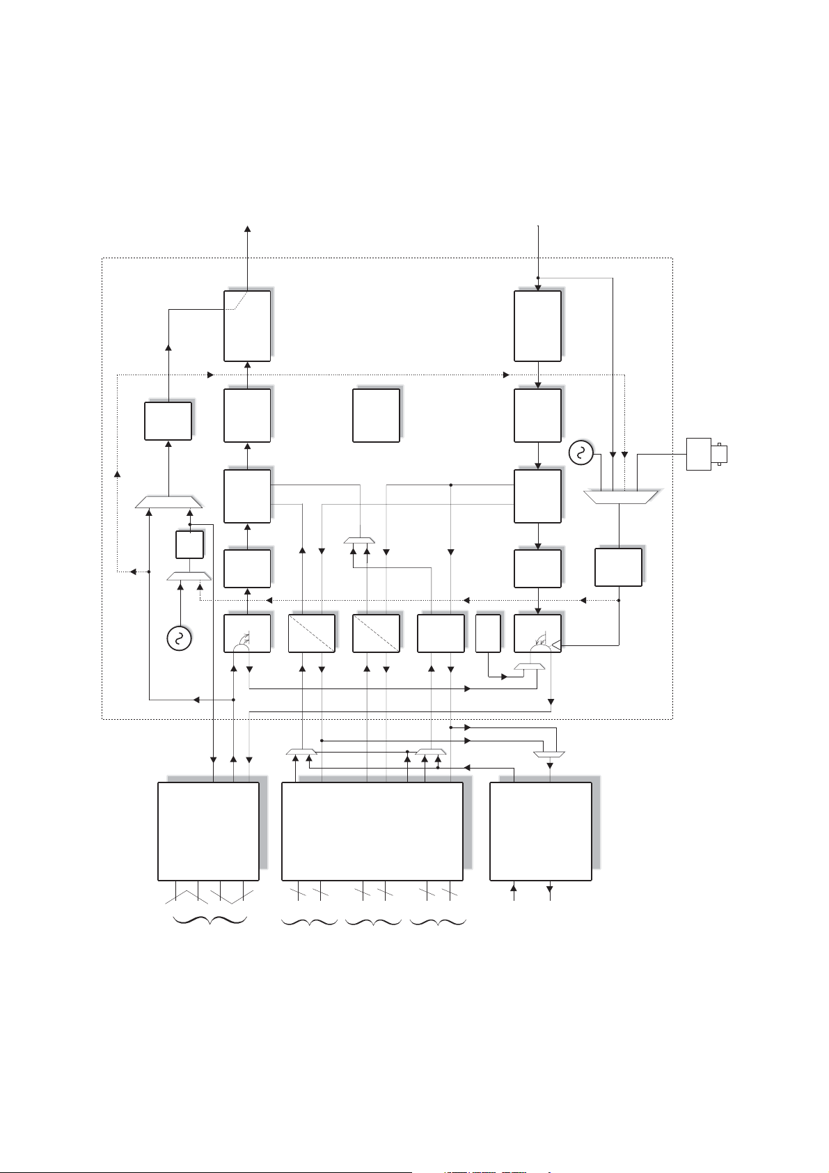
3.6 BL OCK DIA G RAM
To FEC/Modulator
INTERLEAVER
Tx
PLL
Rate
Convert
RS
ENCODER
FRAMER
Tx
FIFO
AUX
ESC
INTERNAL
BER
TESTER
From FEC/Demodulator
DE-
INTERLEAVER
RS
DECODER
AUX
ESC
DEFRAMER
Rx
BUFFER
INTERNAL
1PPM
STATION
CLOCK
Tx CLOCK IN
Rx
PLL
Tx CLOCK IN
INTERNAL
1PPM
Rx
RS422/V.35/
RS449/
CLOCK
INT
CLK
RS232
+G703
OPTION
EIA530/
TWIN BNC
IN
INTERFACE
DATA PORT
DROP
OUT
MUX
SYNC
UART
3P
3P
Sync/Async
ESC.PORT
(sync with
octet timing)
IDR
PCM
ESC
OPTION
2P
Dual 4 wire
audio
32K
ADPCM
IDR OPT
2P
interface
AUX
OUT
DPLL
FITTED
3P
3P
Sync/Async
aux port
(Sync with
Octet timing)
BLANK PCM
MUX
INSERT
FRAME GEN
T1000 ASIC
RS232/422/
485 INTERFACE
“Async port”
P300H P300 Series Modem Installation and Operating Handbook Page 21
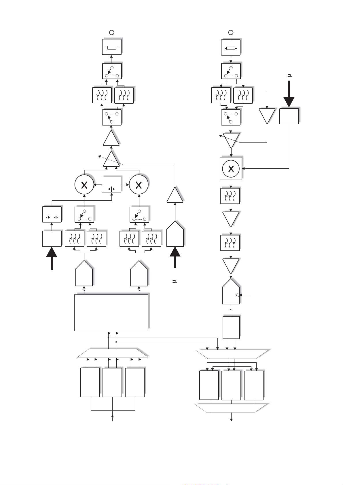
SWITCHED LPF
FILTER BANK
OUTPUT
MATCH
SWITCHED LPF BANK
INPUT MATCH
P
5dB
INTEGRATOR
Rx PLL
SYNTH
2
1
Tx PLL
SYNTH
ANTI-ALIASING
LPF's
8
DAC
AMP
VCA
4
8
DAC
DAC
P
Tx O/P POWER
LEVEL CONTROL
DAC
AGC
DOWN
CONVERT
MIX
LPF
AMP
SAW BPF
AMP
ADC
50 MHz
10
DUAL
FIR
FILTERS
DIGITAL
DEMOD
I
VIT/TCM
From
Q
SEQ
Interleaver
TURBO
VIT/TCM
To
I
Q
SEQ
Deinterleaver
TURBO
P300H P300 Series Modem Installation and Operating Handbook Page 22

4 SUMMARY OF SPECIFICATIONS
Common Main Sp ecifications
Optional features are s hown in [square brackets]
Modulation BPSK, QPSK, OQPSK, [8PSK]
Frequency/Resolution P300: 50 MHz - 90 MHz, 100Hz resolution.
[50 MHz - 180 M Hz Wideband IF feature]
P310: 950MHz - 1750MHz 100Hz resolution
[950 MHz - 2150 M Hz Wideband IF feature]
Traffic Interface
Electrical RS422, V . 35 and RS232 software selectable (clocking can provide X.21
DCE or DTE mode)
Mechanical Both EIA530 DCE and RS449 DCE connectors (25 pin and 37 pin `D`
female respectively).
Options T1 or E1 G.703 in addition to RS422, V.35, & RS232 (software
selectable)
For special requi rements a customer specifi c i nterface card may be fitted.
User Data Rates
Closed Network Resolution of 1 bps
Rate ½ Rate ¾ Rate
f
Uncoded Rate
min 4.8k 7.2k 8.4k 9.6k
BPSK
max * 1250k 1875k 2187k 2500k
min 9.6k 14.4k 16.8k 19.2k
QPSK / OQPSK
mix * 2.5M 3.75M 4.375M 5.0M
min 19.2k
[8PSK/TCM]
mix * 5.0M
[Closed Net plus ESC] As Closed Net above but limits include an overhead of approx 1.4 x ESC
Baud rate. Resolution of 1 bps. ESC from 50Baud to 38.4kBaud
[IBS/SMS Mode] <9.6k to >2048k (6.7% overhead added)
*
Resolution of 1 bps
[IDR Mode] <64k to >2048k (96k overhead added)
*
Resolution of 8k (limitation of frame structure)
b
* Note: Maxi mum dat a rat e is 512kbps in all modes before overheads unless the High
Data Rate option is fitted.
Forward Error [Turbo Product Codec (TPC), Preset rat es inc rate ½, ¾,
b
Correction [TCM rate
to IESS 310]
f
, & 0.789]
P300H P300 Series Modem Installation and Operating Handbook Page 23

[Viterbi, rate ½, ¾, or f, k = 7 to IESS 308/309, 3 bit soft decision
decoding]
f
[Sequential rate ½, ¾, or
to IESS 312, 2 bit soft decision decodi ng]
Reed-Solomon outer FEC [Concatenated Reed Solomon outer codec to IESS 308/310] [Optional
vari able code rate]
Reed-Solomon, Turbo, TCM, Viterbi, & Sequential are independent F E C options, all
may be fitted s imultaneously.
Scrambling
IBS/SMS Synchronised to framing, per IESS 309
IDR & Closed Net With RS Codi ng: synchronis ed to RS overhead.
No RS Coding, non Turbo: V .35 self synchronis ing.
No RS Coding, Turbo: S y nchronous 2 -1 (sync to TPC block alignment).
12
Closed Net plus ESC 32kbps or above, synchronised to ESC overhead. Less than 32kbps, as
per Closed Network.
V.35 scrambler has CCITT, INTELSAT, `FDC` & `Linkabit`modes
S
IF Ports BNC female, 50
& 75S. Return loss 18dB typical.
External reference Clocking only: 1kHz-10M Hz in 1kHz steps (See St ation Reference).
Clocking & Frequency: 10MHz, 0dBm ± 1dB
Modulator Specifications
Output Power Level P300: 0 to -25dBm conti nuously variable in 0.1dB steps from front panel
or vi a remote control
P310: -5 to -30dBm continuous ly v ari able in 0.1dB steps from front panel
or vi a remote control
E
Output Level Stability ±0.5dB at 25
Transmit Filtering 6th order Butterworth, aperture and group delay equalised, INTELSAT
IESS compliant
Filter I mplementation 257 tap FIR digital filter
Occupied Bandwidth 1.2 times symbol rate
Recommended 1.4 times symbol rate
Channel Spacing
Phase and Amplitude ± 2 degrees, ± 0.2dB , max
Accuracy
C ±10EC
Carrier Suppression -30dBc, min.
Output Phase Noise <1.0 degrees RM S double sided, 100Hz to 100kHz
E
Output Frequency Stability As per internal reference from 0
C to 50EC (See Internal Reference
below)
P300H P300 Series Modem Installation and Operating Handbook Page 24

Harmonics and Spurious Better than - 55dBc/4 kHz
Transmit On/Off Ratio 55dB minimum
External Transmit Inhibit By external contact closure or by TTL signal applied to rear panel
connector. Hardware functi on overrides processor control
Demodulator Specifications
IF Input Range P300: -45dBm nominal, ±15dB (desired carrier)
P310: -20 to -70dBm (desi red carrier)
Maximum Composite Signal P300: 30dB above level of desired input up to a maxi mum of 0dBm
P310: 35dB above level of desired input up to a maximum of -10dBm
Frequency Acquisition Selectable from ± 1 kHz to ± 32 kHz
Range
Acquisi tion Threshold < 5dB Eb/No
Acquisition Time @ 9.6 kbps < 3 seconds at 6dB Eb/No
(rate ½ FEC) @ 64 kbps < 2 seconds at 6dB Eb/No
@ 2048 kbps < 500 ms at 6dB Eb/No
Clock Tracking Range ± 100 ppm min
Receive Filterin g 6th order But terw ort h, group delay equalis ed (I NTELSA T IESS compliant)
BER Perfor mance In al l case s met in the presence of two adjacent carriers each 10dB
higher than the desired carrier, with V.35 scrambling
These figures meet or exceed the relevant IESS performance
specifications.
f
Rate ½ Rate ¾ Rate
-4
Viterbi
(all rates)
Sequential
(64kbps)
Sequential
(2048kbps)
Turbo (TPC, QPSK)
(all rates)
8PSK/TCM
(all rates)
8PSK/TCM + Reed- 1 x 10 6.1dB
Solomon
(all rates)
1 x 10 4.7dB 6.1dB 7.1dB
-8
1 x 10 7.2dB 8.8dB 9.5dB
-4
1 x 10 4.3dB 5.4dB 6.4dB
-8
1 x 10 6.4dB 7.3dB 8.6dB
-4
1 x 10 5.6dB 6.1dB 6.9dB
-8
1 x 10 7.5dB 8.1dB 8.4dB
-4
1 x 10 2.6dB 3.5dB 6.0dB
-8
1 x 10 3.7dB 4.5dB 8.3dB
-3
1 x 10 6.3dB
-8
1 x 10 10.4dB
-4
-10
1 x 10 7.3dB
Rate
b
P300H P300 Series Modem Installation and Operating Handbook Page 25

BER performance with
concatenated RS BER improvement depends on n and k values chosen, but a typical
increase in coding gain of 3dB is possible over basic Viterbi mode.
Monitor Functions Measured FEC input B ER (raw channel, not TCM)
Estimated FEC output BER (not TCM)
Measured Reed-Solomon input B E R
Estimated Reed-Solomon output BER
Measured deframer FAW BER
Measured Eb/No (not based on channel BER, range: 3.0-15.0dB,
accuracy ±0.2dB).
Measured frequency offset (± 100 Hz resolution)
Clocking and Buffering
Clock Loops Frequency locked loops giv e phas e hit immune operation even with poor
clock sources such as routers et c.
Tx Clocking Internal Reference (see Internal Reference below for stability)
External - tracking range ±100 ppm / min.
Rx Timing - slaves Tx internally generated timing from Rx clocking
wh atever Rx clocking mode is selected eg wit h Rx=Satellite for loop
timing (with ful l asym m etr i c ra te capability), or with Rx=Station for
both Tx & Rx clocking slaved to Station Clock (again with full
asymmetric rate capability).
Rx Clocking Clock from satellite (Buffer disable)
Tr ansmit input clock - (plesiochronous, includes full asymmetric rate
operation)
Internal Reference (see Internal Reference below for stability)
DCE External timing clock (DTE interface only ).
Stati on reference (s ee below)
Internal Reference P300: +/-1PPM
P310: Default as per P300. Options: 7x10⁻⁷ per year (P313B), 1x10⁻⁷
per year (P313C), 7.5x10⁻⁸ per year (P313D).
S
Station References inputs 75
Buffer Size Selectable in 1 ms increments from 0 to 99 ms. Automatically adjusted
BNC f emale, transformer isolated 1MHz to 10MHz in 1kHz steps
(accepts si nus oid >0dBm or squarewave eg G.703 para 10)
S
RS422 compatible input, 1kHz to 10MHz in 1kHz steps
120
When set to 10MHz, t he st ati on reference may replace internal reference
to all internal circui try (eg I F sy nt hs). The unit automatically switches back
to the internal reference if the station reference fai ls.
to slip an i nteger multiple of terrestrial multiframe length for framed rates
(T1/E1).
Buffer s torage is 32kBy t es, so above 2.6 Mbps max buffer size reduces
linearly from 99 ms to 52ms at 5.0Mbps
P300H P300 Series Modem Installation and Operating Handbook Page 26

Framing & Deframing
Formats Closed Network (unframed)
Closed Net plus ESC [As ync ESC Feature] provides variable rate async
ESC, optional synchronous scrambler above 32kbps to replace error
multiplying V. 35 scrambler, optional backward alarm facility, and optional
Tim esl ot ID Maintenance when used with Drop/Insert, all in minimum
possible overhead down to <0.5%.
INTE LS AT IBS & E ut els at S M S [ I B S/ S MS Feature]. Framing to IESS 309
& IESS 310
INTELSAT IDR [IDR Option]. Framing to IESS 308 & IESS 310
Custom Framing [ `Cus tom Features` feature]. Provides custom framing
based on IBS or I DR formats. For example the use of 16 kbps ADPCM
on the IDR audio ESC channels, providing an IDR carrier with all normal
facili ties but with 32kbps of overhead spare for continuous traffic quali ty
BE R mo nitori n g ( u s ing b uilt in PRBS t e s t er wi th automatic results logging
or external BERT)
Poor BER performance Deframer includes extended threshold operation which improves
performance when used with Reed-So lomon in very poor BER condi t ions
(where a single u ncorrectable RS codeword can contain enough corrupt
frame alignment words to knock an INTELSAT specified deframer out of
frame sync).
[INTELSAT Reed S o lomon Codec & Custom Featu r es]
Format Concatenated Reed Solomon outer codec to IESS 308/310
Code Rate Default n, k, t = (126, 112, 7) depth 4, automatically switching to: (225,
205, 10) depth 4 for 1544 kbps I DR mode. (219, 201, 9) depth 4 for 2048
kbps IDR mode & TCM <=1544 kbps, and (219, 201, 9) depth 8 for TCM
>1544 kbps
Processing Del ay Combined Encoder & Decoder: 8 x (2n - k + 60)
Combined Interleaver & De-interleaver: 8 x n x depth (Calculate delay
time using dat a rate including RS ov erhead)
[Custom Features] When available allows arbitrary selection of `n` & `k` to provide fully
vari able code rate.
`n` = 60-255
`k` = n-2 to n-20 step 2
Interleaving depth of four or eight
The `Custom Features` Feature allows use of shorter codewords to
reduce interleaver / de-interleaver delay on low data rate circuits. For
example switching from n, k, t = 126, 112, 7 to 64, 56, 4 provides
approximately the same correction ability (7 in 126 = 5.5% and 4 in 64 =
6.25% respectively), with similar overheads (126/112=12.5%,
64/56=14.3%), but wi t h i nterleav i ng & decoder delays reduced from 5632
to 3104 bits (156 ms to 85 ms at 32 kbps).
P300H P300 Series Modem Installation and Operating Handbook Page 27

[Drop /Insert Feature]
Bearer Types T1-D4, T1-ESF, and G.732.
Timeslot Selection Independent selection of arbi t rary timeslots for both Drop and Insert.
Bearer Generation The terrestri al bearer may be looped through the Drop mux then Insert
mux, or terminated after the Drop mux and a new blank bearer
generated by t he I nsert mux . The bearer generated within t he Insert mux
provides full multiframe and CRC support and may be generated from
the Tx Clock, S t ation Reference, Satellite Clock or I nternal reference.
Bearer Backup In the event that the Insert mux bearer clock is lost, or AIS is supplied,
then the Insert mux will switch temporarily to bearer generation mode in
order to preserve the receive traffic. The backup bearer may be
generated from the Station Reference, Satellite Clock or Internal
reference.
Terrestrial CRC Fully supported, w i th front panel display of terrestrial error rate based on
CRC (T1-ESF and G.732) or Frame Alignment Word errors (all bearer
types)
Timeslot ID Maintenance The IBS /SMS o r Closed N et p l us ESC overhead maintains the identity of
individual D/I timeslots for N=1, 2, 3, 4, 5, 6, 8, 10, 12, 15, 16, 20, 24, 30
(see Extended D/I F eat ure below ).
[Extended Drop/ Insert Feature]
Timeslot Re-ordering Selec ted timeslots may be independently re-ordered on both Tx and Rx
paths.
Timeslot ID Maintenance The IBS /SMS o r Closed Net plus ESC overhead is ex tended to maintain
the identity of individual D/I timeslots for all values of N from 1 to 31,
including the previ ously unavailable values N=7, 9, 11, 13, 14, 17 - 19, 21
- 23, 25-29, and 31.
Multi-destinational working All or only a subset of the received data may be inserted into the
terrestrial bearer on the receive path for multi-dest inational worki ng.
Signalling Both Channel Associated Signalling (CAS), and Robbed Bit Signalling
(RBS) are fully supported:
For E1 G.732 Drop/Ins ert, CA S s i gnalling is extracted from terrestrial
TS1 6 and carried over the satellite in IBS/SMS TS16 and TS48
before re-inserting into the distant terrest rial TS16
For T1-D4 and T1-ESF RBS the IBS or Closed Net plus ESC
overheads maintain the identity of the in band signalling, and it is
re- inserted into the terrestrial multiframe in the correct positions to
maintain the RBS.
[Async ESC Feature] & Au x Data Ch an ne l
P300H P300 Series Modem Installation and Operating Handbook Page 28

ESC/Aux Port A single port provides the interface for optional high rate async ESC
(IBS /S M S or Closed Net plus ES C), or the INTELSAT low rate async IBS
ESC channel.
Electrical Interface RS232, RS422, or RS485 external i nterfaces or internal link to Remote
M&C port (software selected). No external cabling required between the
ESC and M&C ports for M&C via ESC channel within overhead. Other
devices externally wired in parallel with M&C port can also be accessed
remotely.
A u x Data Chan n el
IBS INTELSAT low rate async ESC definition carried in bit 1 of TS32
provi di ng a sy nchronous channel at 1/480th of the data rate, allowing up
to o ne quarter of this rate for oversampled async data. Compliant with
INTELSAT IESS 403 low rate ES C definition.
[A sync ESC Feature]
Closed Net plus ESC Overhead scales to provide any user specified async ESC Baud rate
wh atever the satellite da ta r ate. ES C li mit is approx 70% of main channel
rate, ov erhead varies from <0.5% to >70%
IBS/SMS Hig h rate asyn c data usi ng from 1/32nd to 22/32nd of the IBS overhead,
pro viding async baud rates from 0.2% to 5.1% of the terrestrial rate (eg
up to >2400 Baud at 64 kbps). I ncludes modes compatible wi t h the P400
Series, P230 & P1300/P1361 (using 20/32nd of the overhead).
[IDR Option]
IDR ESC Audio Interface Two 32 kbps ADPCM channels, 4 wire 600S, +7dBm to -16dBm
(software programmable in 0.1dB steps)
Backward Alarms Outputs: F our `form C` relays
Inputs: Four protected inputs, short to 0 V to send alarm, with matching
summary Rx fail output. Alarm inputs softw are configurable for:
a) all external patch
b) 1=Rx fail & 2-4=External Patch
c) 1=Rx Fail & 2-4=OK
d) 1-4=Rx F ail.
ESC/Aux Ports When the IDR option is fitted, independent ESC & Aux ports on the IDR
option replace the single shared ESC/Aux port of the base unit .
ESC Port RS232, RS422, or RS485 external interfaces or internal link to Remote
M&C port (software selected). No external cabling required between the
ESC and M&C ports for M&C via ESC channel within overhead. Other
devices externally wired in parallel with M&C port can also be accessed
remotely. Prov ides Clock, Data, & Sync (Octet timing) lines.
IDR Synchronous access to 8 kbps IDR ESC. With the Async ESC feature
(standard on P300-IBS and above) async ESC access to the 8kbps IDR
ESC is provided, gi ving up to a 9600 Baud as ync channel
P300H P300 Series Modem Installation and Operating Handbook Page 29

Others IBS & Cl osed Net plus E S C facilities as before installation of IDR opt ion,
but now on ESC port on IDR card not s hared ESC/Aux port of base unit.
Aux Port RS232 or RS422 (software selected). Provides Clock and Data lines .
IDR Provides 32 or 64 kbps access in place of one or both Audio ESC
channels.
IBS INTELSAT low rat e ESC mode as prev i ously but now via Aux port on IDR
car d n o t shared ESC/Aux port of base unit. IDR option also adds sync
IB S mode, configurable to use between 1/32nd and 21/32nd of the IBS
overhead providing a full sync Aux port at between 0.2% and 4.3% of
main data rate.
Aux por t provides satellite ti ming information for P1500 Slave Frequency
Standard when not configured for Aux data access.
P1348 Emulation The IDR Opti on i ncludes the facili ty to emulate the more common modes
of our popular P1348 / P1448 voice / data mux cards which are used
extensively in SNG applicati ons. It uses the IDR audio E SC ports for the
audio int erfaces and can generate a 64 kbps carrier consisting solely of
two 3 2kbps ADPCM encoded audio channels, or a 128 kbps carrier
com pr ising the two audio channels plus 64 kbps data from the main
in t e rf a ce . Th is i s compa t i b le w ith a P4 00 Seri es modem fitted wi th P1448
card or a P230 M odem with a P1348 card, alternatively Drop/I nsert can
be used at the distant end to place the two 32kbps ADPCM audio
channels in one ti meslot and the 64 kbps data in another.
[PRBS Tester Feature]
BER Channel P RBS tester may operat e through either main traffic, ES C data, or AUX
data c h an nel s (main traffic channel not available in Closed Net, ie no
overhead mode). Use of ESC & AUX data channels allow continuous
real traffic BER performance monitoring on links with overhead.
Test Patterns 2047, 2 -1, 2 -1, compatible wit h common stand alone BER testers .
Results Di splay of error count & average B ER
Autolog Auto matic logging of average and 1 minute worst case BER at user
specifi ed intervals (1 min - 24 hours)
15 20
[Monitor/ AGC Op tion]
Facilities Provided Demodulator Rx carrier signal monitori ng & level display (±5dB)
0 -10 V Analog output (Signal level, Eb/No or Rx offset frequency)
Buffered constellation monitor port
Sounder for audible feedback from keyboard
Traffic Log
Capacity Total 1000 entries
P300H P300 Series Modem Installation and Operating Handbook Page 30
 Loading...