

Compact Outdoor
Solid State Power Amplifier
Operations Manual
Paradise Datacom LLC Phone: (814) 238-3450
328 Innovation Blvd. Fax: (814) 238-3829
State College, PA 16803 USA Web: www.paradisedata.com
Email: sales@paradisedata.com
205486 REV F ECO 16101 04/21/2010

Paradise Datacom
328 Innovation Blvd.
State College, PA 16803 USA
Telephone: (814) 238-3450
Fax: (814) 238-3829
E-mail: sales@paradisedata.com
© 2010 Paradise Datacom LLC
Printed in the USA
2 205486 REV F Operations Manual, HPA2, Compact Outdoor SSPA

Table of Contents
Section 1: General Information .......................................................................................... 9
1.0 Introduction ........................................................................................................... 9
1.1 Description ............................................................................................................ 9
1.2 Specifications ........................................................................................................ 9
1.3 Equipment Supplied .............................................................................................. 9
1.4 Safety Considerations ......................................................................................... 10
1.4.1 High Voltage Hazards ........................................................................... 10
1.4.2 RF Transmission Hazards .................................................................... 10
Section 2: Installation ........................................................................................................ 11
2.0 Introduction ......................................................................................................... 11
2.1 Inspection ........................................................................................................... 11
2.2 Prime Power Connection [MS3102E20-3P] ........................................................ 11
2.3 DC Input Option [MS3102E-20-29P] ................................................................... 13
2.4 Summary Alarm Indicator ................................................................................... 13
2.5 Cable Connections .............................................................................................. 13
2.5.1 RF Input (J1) [N-type (F)] ...................................................................... 14
2.5.2 Monitor & Control Connector (J4) [MS3112E18-32S] ........................... 14
2.5.3 Link Port (J5) [MS3112E10-6S] ............................................................. 14
2.5.4 RF Output Sample Port (J3) [N-type (F)] ............................................... 15
2.5.5 Switch Port (J6) [MS3112E10-6S] ......................................................... 15
2.5.6 15 VDC Output Port (J8) [MS3112E10-6S] ........................................... 15
2.5.7 Chassis Ground Terminal ...................................................................... 15
2.5.8 AC Input (J7) ........................................................................................ 16
2.5.9 RF Output (J2) ...................................................................................... 16
2.6 Airflow ................................................................................................................. 16
2.7 Fiber-Optic Option ............................................................................................... 17
2.7.1 RCPF-1000 Fiber Optic Controller ........................................................ 17
2.7.2 External L-Band to Fiber Interface ........................................................ 18
2.8 Unit Weights........................................................................................................ 20
2.9 Compact Outdoor Mounting Kit Installation ......................................................... 21
2.9.1 Safety Considerations ........................................................................... 21
2.9.2 Inspection .............................................................................................. 21
2.9.3 Installation ............................................................................................. 22
Section 3: Operation .......................................................................................................... 25
3.0 Introduction ......................................................................................................... 25
3.1 RF Input (J1) ....................................................................................................... 25
3.2 RF Output (J2) .................................................................................................... 25
3.3 Amplifier Enable (Mute/Unmute) (J4) .................................................................. 25
3.4 Alarms (J4) .......................................................................................................... 27
3.4.1 Summary Alarm (J4) Form C Contacts ................................................. 27
3.4.2 Auxiliary Alarm (J4) Form C Contacts ................................................... 27
3.4.3 Open Collector Alarm Outputs (J4) ....................................................... 27
3.5 RF Power Detector (J4) ...................................................................................... 28
Operations Manual, HPA2, Compact Outdoor SSPA 205486 REV F 3

3.6 RF Output Sample (J3) ....................................................................................... 28
3.7 Gain Adjust Input (J4) ......................................................................................... 28
3.8 Serial I/O Control (J4) ......................................................................................... 28
3.9 Compact Outdoor Amplifier Quick Start Guide .................................................... 29
3.9.1 Status Window ...................................................................................... 30
3.9.1.1 Signal Indicators ...................................................................... 31
3.9.1.2 Fault Status Indicators ............................................................. 31
3.9.1.3 Voltage, Current and Temperature Display ............................. 32
3.9.1.4 Gain Adjustment ...................................................................... 32
3.9.1.5 RF Power Indicator .................................................................. 33
3.9.1.6 Carrier Enable.......................................................................... 33
3.9.2 Settings Window .................................................................................... 33
3.9.2.1 Power Up Settings ................................................................... 34
3.9.3 Universal M&C Preferences .................................................................. 36
Section 4: Theory of Operation ........................................................................................ 37
4.0 Introduction ......................................................................................................... 37
4.1 EMI Filter and Transient Protection ..................................................................... 38
4.2 Power Supply ...................................................................................................... 38
4.2.1 AC / DC Converter ................................................................................ 38
4.2.2 DC / DC Converter ................................................................................ 38
4.3 Solid State Power Amplifier Module .................................................................... 38
4.4 Fan Boost Converter ........................................................................................... 39
4.5 Cooling System ................................................................................................... 39
Section 5: Performance Tests .......................................................................................... 41
5.0 Introduction ......................................................................................................... 41
5.1 Gain and Gain Flatness ...................................................................................... 41
5.2 P1dB ................................................................................................................... 41
5.3 Input and Output Return Loss ............................................................................ 41
5.4 Spurious .............................................................................................................. 41
5.5 RF Sample Port................................................................................................... 41
5.6 Intermodulation Distortion ................................................................................... 42
Section 6: Maintenance ..................................................................................................... 43
6.0 Introduction ......................................................................................................... 43
6.1 Cooling System Maintenance ............................................................................. 43
6.2 Fan Removal ....................................................................................................... 43
6.2.1 Fan Replacement .................................................................................. 44
6.3 Connector Weatherproofing ................................................................................ 44
Section 7: Redundant System Operation ........................................................................ 45
7.0 Redundant System Concepts ............................................................................. 45
7.1 Compact Outdoor Amplifier in 1:1 Redundancy .................................................. 47
7.1.1 Hardware Setup .................................................................................... 48
7.1.2 Software Setup ...................................................................................... 49
7.1.2.1 Stand-Alone 1:1 Redundant System ........................................ 49
7.1.2.2 PC Control using RS232 and Universal M&C Software .......... 52
7.1.2.3 PC Control using RS485 and Paradise M&C Software ........... 57
7.2 1:2 Redundant Systems ...................................................................................... 59
7.3 1:2 Redundant Systems with L Band Input ......................................................... 62
4 205486 REV F Operations Manual, HPA2, Compact Outdoor SSPA

Section 8: Fixed Phase Combined Redundant Systems ................................................ 67
8.0 Phase Combining Overview ................................................................................ 67
8.1 1:1 Fixed Phase Combined System Components ............................................... 69
8.1.1 Signal Box Assembly ............................................................................. 69
8.2 1:1 Fixed Phase Combined System Operation with the FPRC-1100 .................. 71
8.3 1:1 Fixed Phase Combined System with L-Band Input ....................................... 72
8.3.1 1:1 Fixed Phase Combined System with L-Band Input Components .... 73
8.3.2 Signal Box Assembly ............................................................................. 73
8.3.3 Redundant BUC Operation ................................................................... 73
8.3.4 Identifying a BUC Fault vs. SSPA Fault ................................................ 73
8.3.5 Adjusting the Phase Combining ............................................................ 75
8.4 1:2 Fixed Phase Combined Systems .................................................................. 75
8.4.1 1:2 Fixed Phase Combined System Components ................................. 76
8.4.2 Signal Box Assembly ............................................................................. 76
8.5 1:2 Fixed Phase Combined System Operation with FPRC-1200 ........................ 78
8.5.1 Output Power Adjustment ..................................................................... 79
Section 9: L Band Operation ............................................................................................ 81
9.0 Block Up Converter Overview ............................................................................. 81
9.1 ZBUC Features ................................................................................................... 82
9.2 ZBUC Theory of Operation ................................................................................. 83
9.3 Smart Reference Technology ............................................................................. 83
9.4 ZBUC FSK Monitor and Control .......................................................................... 84
9.5 Typical System Configuration ............................................................................. 85
9.6 IFL Cable Considerations ................................................................................... 85
Section 10: Remote Control Interface .............................................................................. 87
10.0 Serial Communication Protocol ......................................................................... 87
10.1 Header Packet .................................................................................................. 87
10.1.1 Frame Sync Word ............................................................................... 87
10.1.2 Destination Address ............................................................................ 87
10.1.3 Source Address ................................................................................... 88
10.2 Data Packet ...................................................................................................... 88
10.2.1 Protocol ID .......................................................................................... 88
10.2.2 Request ID .......................................................................................... 88
10.2.3 Command ............................................................................................ 88
10.2.4 Data Tag ............................................................................................. 89
10.2.5 Error Status / Data Address ................................................................ 90
10.2.6 Data Length ......................................................................................... 90
10.2.7 Data Field ............................................................................................ 90
10.3 Trailer Packet .................................................................................................... 91
10.3.1 Frame Check ....................................................................................... 91
10.4 Timing issues .................................................................................................... 91
10.5 Examples .......................................................................................................... 96
10.5.1 Example 1 ........................................................................................... 96
10.5.2 Example 2 ........................................................................................... 98
10.5.3 Example 3 ......................................................................................... 100
Operations Manual, HPA2, Compact Outdoor SSPA 205486 REV F 5

Section 11: Remote Operation ........................................................................................ 103
11.0 Remote Operation ........................................................................................... 103
11.1 Menu Structure................................................................................................ 104
11.1.1 System Information sub-menu ........................................................... 105
11.1.1.1 Sys Info Page 1 ................................................................... 105
11.1.1.2 Sys Info Page 2 ................................................................... 105
11.1.1.3 Sys Info Page 3 ................................................................... 106
11.1.1.4 Sys Info Page 4 ................................................................... 106
11.1.1.5 Sys Info Page 5 ................................................................... 106
11.1.1.6 Communication Setup sub menu ......................................... 107
11.1.1.7 Operation setup sub menu .................................................. 107
11.1.1.8 Fault Setup sub menu .......................................................... 108
11.2 Configuring SSPA and PC to work with terminal mode protocol ..................... 109
11.2.1 Remote Terminal Set-up ................................................................... 110
Appendix A: Quick Start Cable ....................................................................................... 113
Appendix B: Alternate System Configurations ............................................................. 115
Appendix C: Baud Select Lines on J4 ........................................................................... 117
Appendix D: VSAT BUC Protocol Support .................................................................... 119
Appendix E: Documentation ........................................................................................... 123
Figures
Figure 2-1: Outline, Compact Outdoor Solid State Amplifier ..................................... 13
Figure 2-2: Input Side, Compact Outdoor Amplifier .................................................. 14
Figure 2-3: Bottom View, Compact Outdoor Amplifier .............................................. 15
Figure 2-4: RF Output Side of C Band Compact Outdoor SSPA .............................. 16
Figure 2-5: RCPF-1000 front, rear panels ................................................................. 17
Figure 2-6: Outline Drawing, External L-Band to fiber interface ................................ 18
Figure 2-7: OFM-1000 ............................................................................................... 18
Figure 2-8: Block Diagram, Compact Outdoor with external fiber transceiver ........... 19
Figure 2-9: System example, SSPA with External Fiber to L-Band Converter .......... 19
Figure 2-10: Bolt Mounting Bracket to Unit ............................................................... 22
Figure 2-11: Unit Ready for Boom Installation .......................................................... 22
Figure 2-12: Compact Outdoor Mounting Completed ............................................... 23
Figure 2-13: Outline Drawing, Compact Outdoor Mounting Kit ................................. 24
Figure 3-1: Universal M&C Add Unit menu ............................................................... 29
Figure 3-2: Add Compact Outdoor SSPA window, via Serial or Internet ................... 29
Figure 3-3: Universal M&C Status Window ............................................................... 30
Figure 3-4: Universal M&C Settings Window ............................................................ 33
Figure 3-5: Spare Fault Wizard ................................................................................. 35
Figure 3-6: Preferences Window ............................................................................... 36
Figure 3-7: Example, Log entry ................................................................................. 36
Figure 4-1: Block Diagram, Compact Outdoor Amplifier ........................................... 37
Figure 5-1: IMD vs. Backoff for a 50W Ku Band Compact Outdoor SSPA ................ 42
Figure 6-1: Fan Removal from Amplifier Assembly ................................................... 43
Figure 6-2: MS connector, wrapped with weather-resistant self-sealing tape ........... 44
Figure 7-1: Standard 1:1 Redundant System with input and output switches ........... 45
Figure 7-2: 1:1 Redundant System with input splitter substituted for switch ............. 45
Figure 7-3: 1:1 Redundant System with L Band input ............................................... 46
6 205486 REV F Operations Manual, HPA2, Compact Outdoor SSPA

Figure 7-4: Antenna-mounted 1:1 Redundant Compact Outdoor SSPA System ...... 46
Figure 7-5: Typical 1:1 Redundant System Outline................................................... 47
Figure 7-6: 1:1 Redundant System with Link Cable and Switch Cable installed ....... 48
Figure 7-7: 1:1 System with RS232 Communication to each Amplifier ..................... 49
Figure 7-8: M&C Program “SSPA Settings” window ................................................. 50
Figure 7-9: Adding a SSPA Monitor and Control Window ......................................... 52
Figure 7-10: Add New Compact Outdoor SSPA window .......................................... 53
Figure 7-11: Individual SSPA Operation Window ..................................................... 53
Figure 7-12: Paradise Datacom Universal M&C, Add Unit Menu Tree ..................... 54
Figure 7-13: Add 1:1 Redundant System Window .................................................... 54
Figure 7-14: Paradise Datacom M&C showing configured 1:1 Redundant System .. 55
Figure 7-15: Dialog window, Affirm mute of on-line amplifier .................................... 55
Figure 7-16: Control Panel showing Unit 1 faulted and signal routed to Unit 2 ......... 56
Figure 7-17: Unit1 Status panel showing Summary and Temperature Faults ........... 56
Figure 7-18: 1:1 Redundant System with RS485 Full Duplex Communication ......... 57
Figure 7-19: 1:1 Redundant System with RS485 Half Duplex Communication ......... 58
Figure 7-20: 1:2 Redundant System ......................................................................... 59
Figure 7-21: 1:2 Redundant System Block Diagram ................................................. 59
Figure 7-22: Outline, 1:2 Redundant System ............................................................ 60
Figure 7-23: Schematic, 1:2 Redundant System ...................................................... 61
Figure 7-24: 1:2 System with L Band Input and Internally Referenced BUCs ........... 62
Figure 7-25: 1:2 System with External Reference; no reference to stand-by BUC ... 63
Figure 7-26: 1:2 System with (3) 10MHz inputs through the input switches .............. 64
Figure 7-27: 1:2 System with External Reference using the combiner assembly ..... 65
Figure 8-1: Phase Combined Amplifier System ........................................................ 67
Figure 8-2: 1:1 Fixed Phase Combined System with FPRC-1100 controller ............. 68
Figure 8-3: Outline, 1:1 Fixed Phase Combined System .......................................... 70
Figure 8-4: FPRC-1100 Phase Combined System Controller ................................... 71
Figure 8-5: 1:1 Phase Combined System with HPA control of BUC redundancy ...... 72
Figure 8-6: Outline, 1:1 Fixed Phase Combined System with L-Band Input ............. 74
Figure 8-7: Block Diagram, 1:2 Fixed Phase Combined System .............................. 75
Figure 8-8: Outline, 1:2 Fixed Phase Combined System .......................................... 77
Figure 8-9: FPRC-1200 1:2 Phase Combined Redundant Controller ....................... 78
Figure 8-10: HPA 1 & HPA 3 on line with HPA 2 on standby .................................... 78
Figure 8-11: 1:2 Fixed Phase Combined Compact Outdoor System ........................ 79
Figure 9-1: Configurator, Compact Outdoor SSPA, BUC Options ............................ 81
Figure 9-2: Compact Outdoor Block Diagram of BUC / SSPA System ..................... 82
Figure 9-3: Compact Outdoor SSPB with PD25 Evolution Modem ........................... 85
Figure 10-1: Basic Communication Packet ............................................................... 87
Figure 10-2: Header Sub-Packet .............................................................................. 87
Figure 10-3: Data Sub-Packet .................................................................................. 88
Figure 10-4: Trailer Sub-Packet ................................................................................ 91
Figure 10-5: Example 2 Protocol Debugger Window in M&C Software .................... 99
Figure 10-6: Example 3 Protocol Debugger Window in M&C Software .................. 102
Figure 11-1: Main Menu Structure .......................................................................... 104
Figure 11-2: System Information menu structure .................................................... 105
Figure 11-3: Universal M&C Settings Screen, Modifying Protocol Select ............... 109
Figure 11-4: Verification to Change Protocol .......................................................... 109
Figure 11-5: Connection Description window .......................................................... 110
Operations Manual, HPA2, Compact Outdoor SSPA 205486 REV F 7

Tables
Figure 11-6: Connect To window ............................................................................ 110
Figure 11-7: COM Properties window ..................................................................... 111
Figure 11-8: ASCII Setup window ........................................................................... 111
Figure 11-9: Example of Terminal Mode session .................................................... 112
Figure A-1: Quick Start Cable Schematic ................................................................ 113
Figure B-1: Mixed System using New and Original Compact Outdoor SSPAs ....... 115
Figure B-2: Redundant System using RCP2-1100 Controller ................................. 116
Table 2-1: AC Line Input Connector .......................................................................... 11
Table 2-2: Compact Outdoor Amplifier Prime Power Summary ................................ 12
Table 2-3: DC Input Connector, MS3102E-20-29P ................................................... 13
Table 2-4: Link Port (J5) Pin-Outs ............................................................................. 14
Table 2-5: Switch Port (J6) Pin-Outs ......................................................................... 15
Table 2-6: +15 VDC Output Port (J8) Pin-Outs ......................................................... 15
Table 2-7: Compact Outdoor SSPA Weights ............................................................ 20
Table 2-8: Compact Outdoor SSPA Mounting Kit ..................................................... 21
Table 3-1: Monitor & Control Connector, J4 ............................................................. 26
Table 7-1: Returning Amp 2 to Stand-by Mode After Fault on Thread 1 or 3 ............ 65
Table 9-1: ZBUC Frequency Specifications .............................................................. 82
Table 9-2: ZBUC RF output phase noise specification.............................................. 83
Table 9-3: Common Coaxial Cable Characteristics .................................................. 85
Table 10-1: Command Byte Values .......................................................................... 88
Table 10-2: Data Tag Byte Values ............................................................................ 89
Table 10-3: Error Status Byte Values ........................................................................ 90
Table 10-4: Request Frame Structure ....................................................................... 92
Table 10-5: Response Frame Structure .................................................................... 92
Table 10-6: System Settings Data Values ................................................................. 93
Table 10-7: System Condition Addressing ................................................................ 94
Table 10-8: ADC (Analog-Digital Converter) Addressing .......................................... 95
Table 10-9: System Threshold Data Values .............................................................. 95
Table 10-10: Example 1 Host PC Request String ..................................................... 96
Table 10-11: Example 1 SSPA Response String ...................................................... 97
Table 10-12: Example 2 PC Request String ............................................................. 98
Table 10-13: Example 2 SSPA Response String ...................................................... 98
Table 10-14: Example 3 PC Request String ........................................................... 100
Table 10-15: SSPA Fault Status bit by bit description ............................................. 100
Table 10-16: Example 3 SSPA Response String .................................................... 101
Table C-1: Baud Rate and Protocol Reverting Options ........................................... 117
Table C-2: Unique Network Address Hardware Select ........................................... 117
Table D-1: Suggested Cable Wiring for ND Satcom SkyWAN modems ................. 119
Table D-2: Packet Structure .................................................................................... 120
Table D-3: Response Structure ............................................................................... 120
Table D-4: Power Class Values .............................................................................. 121
8 205486 REV F Operations Manual, HPA2, Compact Outdoor SSPA

Section 1: General Information
1.0 Introduction
This section provides the general information for the Paradise Datacom LLC line of Compact
Outdoor Solid State Power Amplifiers. The Compact Outdoor SSPA has been designed and
manufactured to be an extremely robust and reliable amplifier. It is well suited for harsh
outdoor environments.
1.1 Description
The Compact Outdoor SSPA is a one-piece integrated Satcom amplifier system. It includes
the AC/DC power supply, microwave amplifier module, microprocessor based monitor and
control circuitry, and an efficient thermal management system.
The reduced size and weight of this amplifier system allow it to be used in a wide variety of
installations; many of which historically precluded the use of Solid State power amplifiers.
This amplifier is ideal for mounting on the boom of small antennas or anywhere that size and
weight are a major concern.
Features include:
● Compact Size: 10.0 in x 19.5 in x 6.50 in. (254 mm x 495 mm x 165 mm)
● Very light weight: Base units weigh as little as 36 lb. (16.4 kg)
● Auto-Sensing Power Factor Corrected Power Supply
● RF Gain Adjustment: 55 dB to 75 dB minimum with 0.1 dB resolution
● Output Power Detection
● Output Power Sample Port
● Internal 1:1 Redundant Capability
● Optional L-Band Input Capability
● Serial (RS 232 / RS 485) or Parallel Monitor & Control Circuitry
● Windows Monitor & Control Software
1.2 Specifications
Refer to Appendix E for full specifications of the Compact Outdoor SSPA.
1.3 Equipment Supplied
The following equipment is supplied with each unit:
● The Compact Outdoor Amplifier Assembly;
● Prime power mating connector: AC - MS3106E20-3S; DC - MS3106F20-29S
● Quick Start Serial Communication Cable, L204133-2
● Product Guide CD with SSPA Monitor & Control Software
● M&C (J4) Mating Connector, MS3116F18-32P
Operations Manual, HPA2, Compact Outdoor SSPA 205486 REV F 9

● Waveguide gaskets (dependent on frequency band)
● Sealing tape (87F730)
1.4 Safety Considerations
Potential safety hazards exist unless proper precautions are observed when working with this
unit. To ensure safe operation, the user must follow the information, cautions, and warnings
provided in this manual as well as the warning labels placed on the unit itself.
1.4.1 High Voltage Hazards
Only qualified service personnel should service the internal electronic circuitry of the Compact
Outdoor Amplifier. High DC voltages (300 VDC) are present in the power supply section of
the amplifier. Care must be taken when working with devices that operate at this high voltage
levels. It is recommended to never work on the unit or supply prime AC power to the unit
while the cover is removed.
1.4.2 RF Transmission Hazards
RF transmissions at high power levels may cause eyesight damage and skin burns.
Prolonged exposure to high levels of RF energy has been linked to a variety of health issues.
Please use the following precautions with high levels of RF power.
● Always terminate the RF input and output connector prior to applying prime AC
input power.
● Never look directly into the RF output waveguide
● Maintain a suitable distance from the source of the transmission such that the
power density is below recommended guidelines in ANSI/IEEE C95.1. The power
density specified in ANSI/IEEE C95.1-1992 is 10 mW/cm2. These requirements
adhere to OSHA Standard 1910.97.
● When a safe distance is not practical, RF shielding should be used to achieve the
recommended power density levels.
10 205486 REV F Operations Manual, HPA2, Compact Outdoor SSPA
Section 2: Installation
2.0 Introduction
This section provides information for the initial inspection, installation, external connections,
and shipment of the Compact Outdoor SSPA unit.
2.1 Inspection
When the unit is received, an initial inspection should be completed. First ensure that the
shipping container is not damaged. If it is, have a representative from the shipping company
present when the container is opened. Perform a visual inspection of the Compact Outdoor
Amplifier to make sure that all items on the packing list are enclosed. If any damage has
occurred or if items are missing, contact:
Paradise Datacom LLC
328 Innovation Park
State College, PA 16803
Phone: 1 (814) 238-3450
Fax: 1 (814) 238-3829
2.2 Prime Power Connection [MS3102E20-3P]
The Prime power connector is a 3-pin circular connector, J7. The power supplies provide
universal AC input by using auto-sensing power supplies. The AC input can operate over a
range of 90-265 VAC, at 47 to 63 Hz. The power supply is also power factor corrected,
enabling the unit to achieve a power factor greater than 0.93.
The highest output power levels, >70 W @ Ku-Band and >100 W @ C-Band should be
powered only from a 180–265 VAC source. This will keep AC line currents to safe operating
levels for the internal EMI filter and associated circuitry. The AC Line input connector
configuration is given in Table 2-1. The prime power vs. RF output power is summarized in
Table 2-2. An option for 110 VAC prime power is available for the higher-powered units.
Table 2-1: AC Line Input Connector
J7 Pin Connection
A L1
B GND
C L2/N
Operations Manual, HPA2, Compact Outdoor SSPA 205486 REV F 11
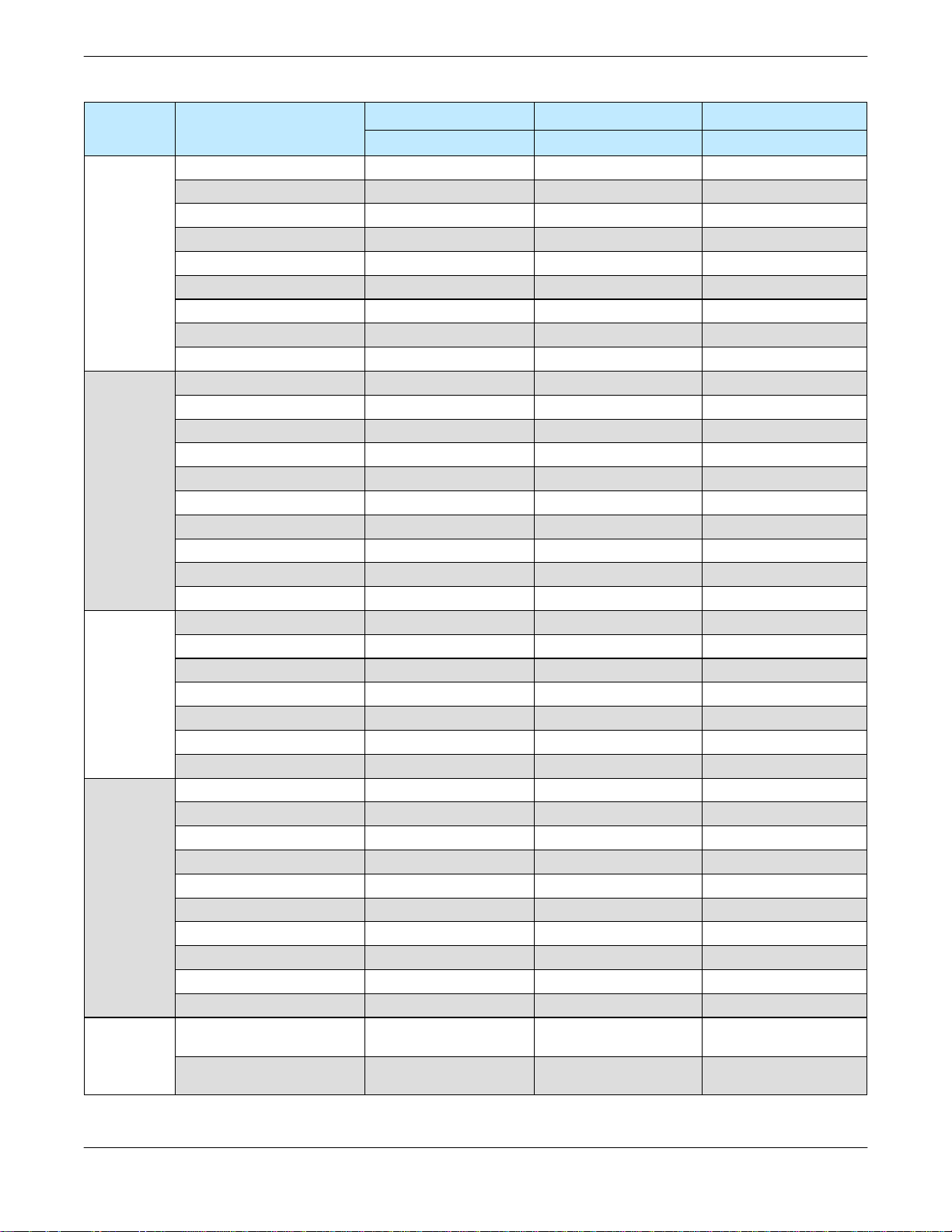
Table 2-2: Compact Outdoor Amplifier Prime Power Summary
Band Model
HPAC2030ACXXXXX
HPAC2040ACXXXXX
5.850 - 6.425 GHz
C-Band
14.000 - 14.500 GHz
Ku-Band
7.900 - 8.400 GHz
X-Band
(unless otherwise indicated)
2.020 - 2.120 GHz
S-Band
30.0 - 31.0
Ka-Band
GHz
HPAC2050ACXXXXX
HPAC2075ACXXXXX
HPAC2100ACXXXXX
HPAC2140ACXXXXX
HPAC2200ACXXXXX
HPAC2250ACXXXXX
HPAC2300ACXXXXX
HPAK2010ACXXXXX
HPAK2020ACXXXXX 43.0/42.0 dBm 90 – 265 vac 250 W
HPAK2025ACXXXXX
HPAK2035ACXXXXX 45.5/44.5 dBm 90 – 265 vac 350 W
HPAK2040ACXXXXX
HPAK2050ACXXXXX 47.0/46.0 dBm 90 – 265 vac 600 W
HPAK2070ACXXXXX
HPAK2100ACXXXXX 50.0/49.0 dBm 180 – 265 vac* 1000 W
HPAK2125ACXXXXX
HPAKG200ACXXXXX
HPAX2060ACXXXXX 47.5/47.3 dBm 90 – 265 vac 650 W
HPAX2075ACXXXXX
HPAX2100ACXXXXX 50.0/49.5 dBm 90 – 265 vac 750 W
HPAX2140ACXXXXX
HPAX2200ACXXXXX 53.0/51.8 dBm 180 – 265 vac* 1370 W
HPAX2250ACXXXXX
HPAXG400ACXXXXX◊
HPAS2050ACXXXXX 47.5/47.0 dBm 90 – 265 vac 425 W
HPAS2100ACXXXXX 50.5/50.0 dBm 90 – 265 vac 650 W
HPAS2200ACXXXXX** 53.5/53.0 dBm 180 – 265 vac* 1000 W
HPAS2200ACXXXXX*** 53.0/52.5 dBm 180 – 265 vac* 1000 W
HPAS2300ACXXXXX** 55.0/54.5 dBm 180 – 265 vac* 1600 W
HPAS2300ACXXXXX*** 54.4/54.0 dBm 180 – 265 vac* 1600 W
HPAS2050BCXXXXX
HPAS2100BCXXXXX@ 50.5/50.0 dBm 90 – 265 vac 650 W
HPAS2200BCXXXXX
HPAS2300BCXXXXX@ 55.0/54.5 dBm 180 – 265 vac* 1600 W
HPAKA020ACXXXXX 43.0/-- dBm 90 – 265 vac 280 W
RF Output Power AC Input Voltage AC Input Power
P
/ P
sat
45.0/44.8 dBm 90 – 265 vac 250 W
46.0/45.8 dBm 90 – 265 vac 300 W
47.0/46.8 dBm 90 – 265 vac 400 W
48.8/48.5 dBm 90 – 265 vac 450 W
50.0/49.5 dBm 90 – 265 vac 700 W
51.5/51.0 dBm 180 – 265 vac* 850 W
53.0/52.3 dBm 180 – 265 vac* 1000 W
53.9/53.0 dBm 180 – 265 vac* 1300 W
54.7/54.0 dBm 180 – 265 vac* 1700 W
40.0/39.0 dBm 90 – 265 vac 220 W
44.0/43.0 dBm 90 – 265 vac 320 W
46.0/45.0 dBm 90 – 265 vac 550 W
48.5/47.5 dBm 90 – 265 vac 650 W
51.0/50.0 dBm 180 – 265 vac* 1150 W
◊
52.5 dBm (P
48.8/48.3 dBm 90 – 265 vac 700 W
51.4/50.8 dBm 180 – 265 vac 1225 W
54.0/53.0 dBm 180 – 265 vac* 1550 W
56.0 dBm (P
@
47.5/47.0 dBm 90 – 265 vac 425 W
@
53.5/53.0 dBm 180 – 265 vac* 1000 W
Operating Range Maximum
1dB
) 90 – 265 vac 1910 W
3dB
) 90 – 265 vac 2000 W
3dB
HPAKA040ACXXXXX 46.0/-- dBm 90 – 265 vac 520 W
* Optional 110 vac operation available; ** 2.020 - 2.090 GHz; *** 2.095 - 2.120 GHz
@
2.200 - 2.300 GHz
◊
GaN module (P
3dB
only)
12 205486 REV F Operations Manual, HPA2, Compact Outdoor SSPA
2.3 DC Input Option [MS3102E-20-29P]
The Compact Outdoor Amplifier can also be configured with a DC Input Voltage power
supply. The DC Input Voltage can range from 42-60 VDC. When using a DC input voltage
the input power connector, J7, is configured per Table 2-3.
Table 2-3: DC Input Connector, MS3102E-20-29P
Pin # on J7 Connection
B +48 V
C +48 V
D +48 V
K -48 V
Pin # on J7
L
M
N
Connection
-48 V
-48 V
GND
2.4 Summary Alarm Indicator
A summary alarm indicator LED is located on the input side of the amplifier. When the SSPA
is online, this indicator illuminates GREEN. When in a fault condition, it illuminates RED.
2.5 Cable Connections
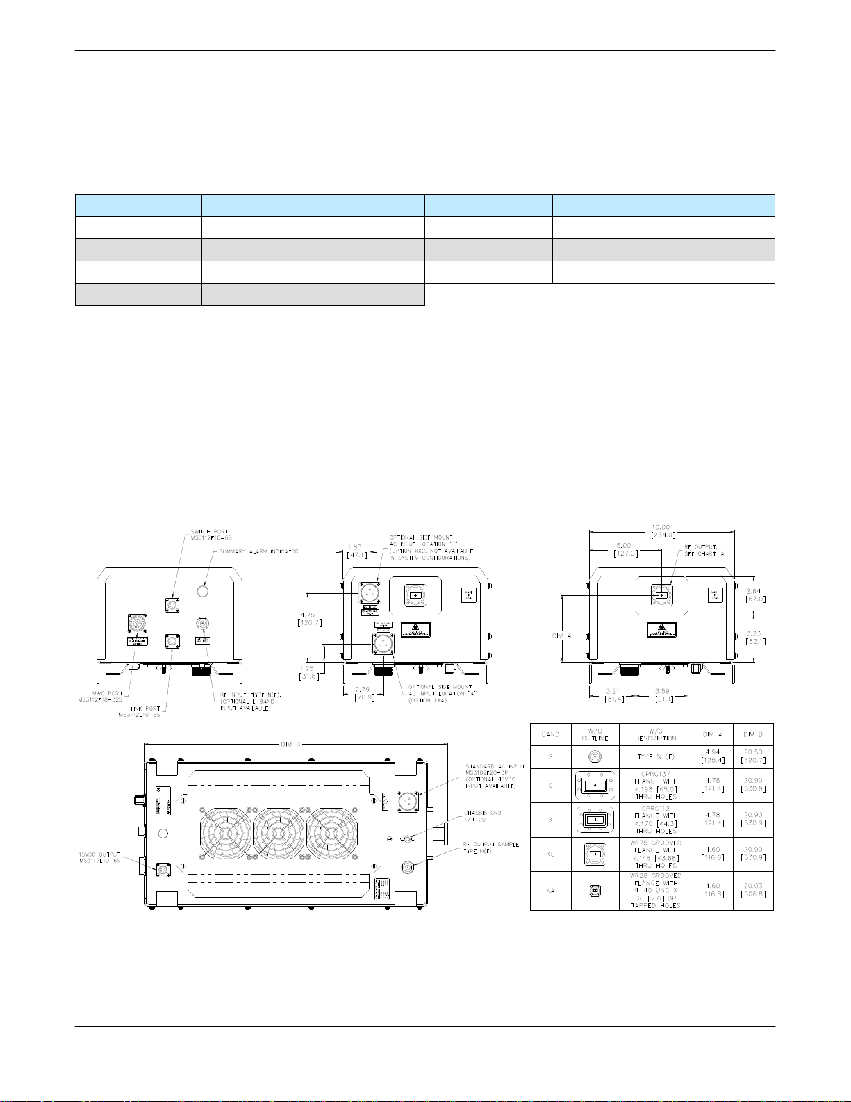
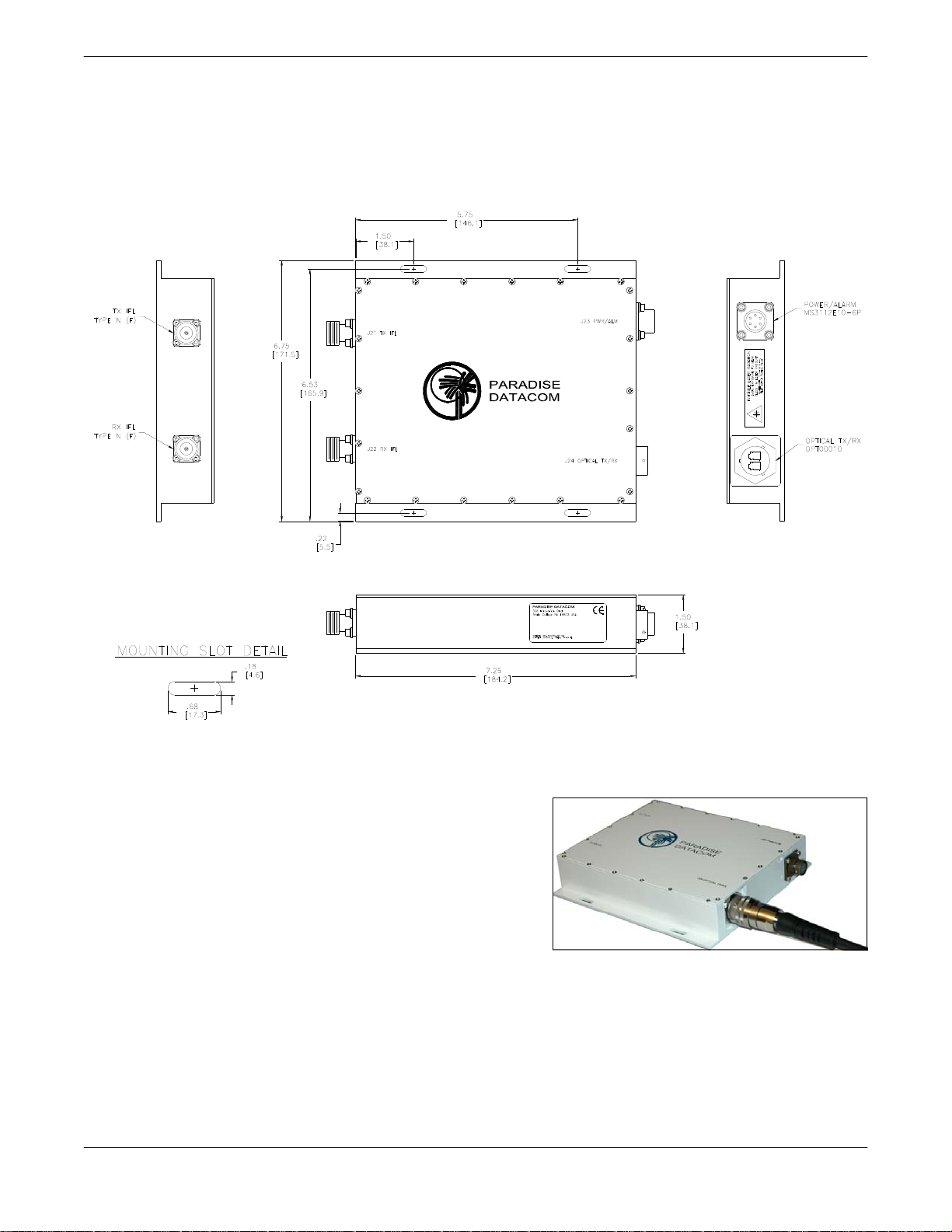
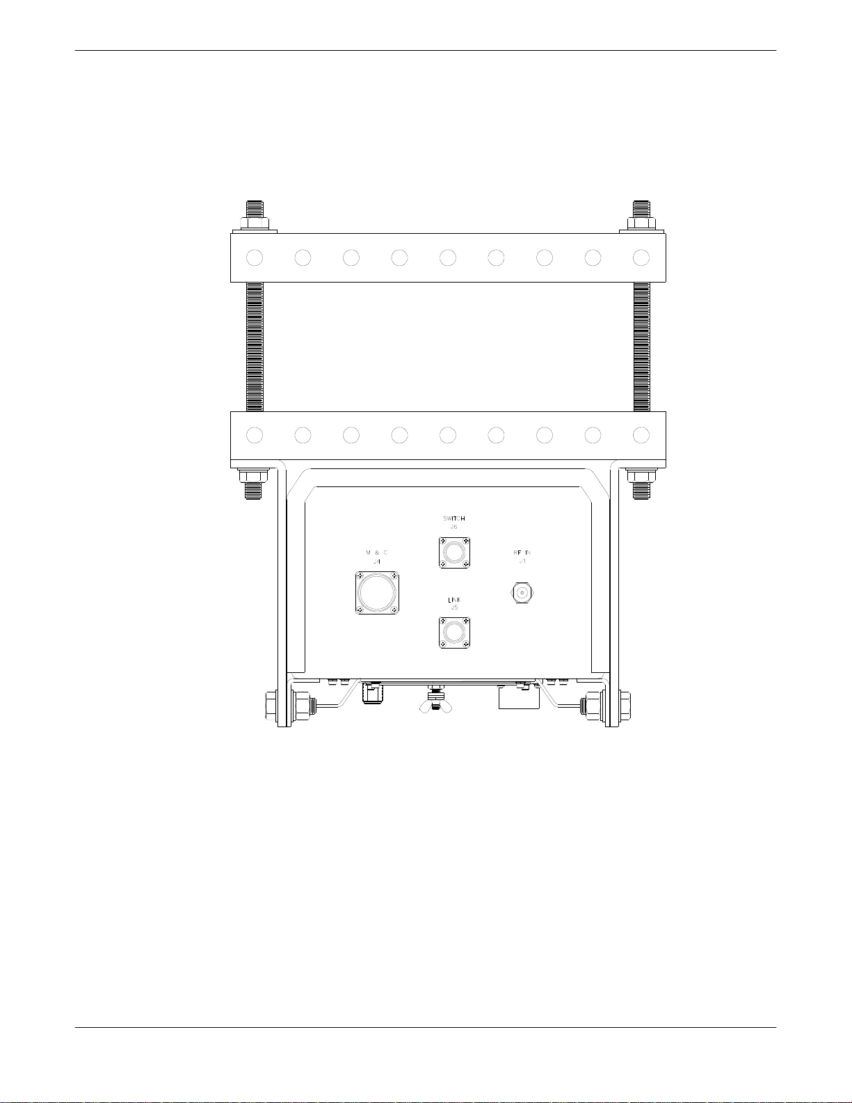
Figure 2-1 shows the dimensioned outline of the Compact Outdoor Amplifier, displaying the
connector locations. The connector locations can be found in Figures 2-2 through 2-4.
SSPA
STATUS
SWITCH
J6
M & C
J4
J8
AUX POWER
RF IN
J1
LINK
J5
P/N: LXXXXXX-X
MODEL: XXXXXXXXXXXX
S/N: XXXX
J7
AC IN
J3
SAMPLE
RF OUT
J2
RF OUT
J2
Figure 2-1: Outline, Compact Outdoor Solid State Amplifier
Operations Manual, HPA2, Compact Outdoor SSPA 205486 REV F 13
SSPA
STATUS
SWITCH
J6
M & C
J4
LINK
J5
RF IN
J1
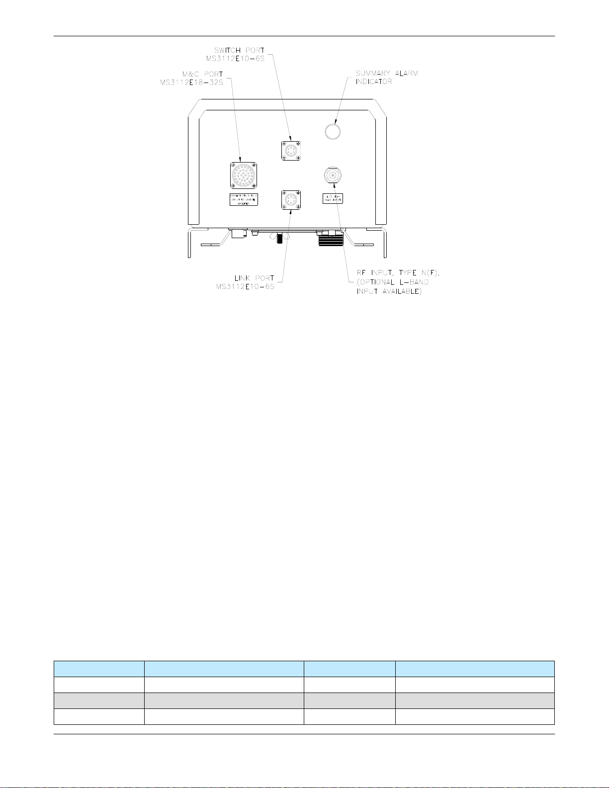
Figure 2-2: Input Side, Compact Outdoor Amplifier
Figure 2-2 shows the input side of the Compact Outdoor Amplifier. This side contains the RF
input (J1), M&C input (J4), and the Interface connections (J5, J6).
2.5.1 RF Input (J1) [N-type (F)]
The RF Input connector is a type N female connector. Nominal RF input levels are approximately -28 dBm depending on the output power level of the unit. The maximum allowable RF
input signal should be limited to +15 dBm.
2.5.2 Monitor & Control Connector (J4) [MS3112E18-32S]
The M&C, Monitor and Control, connector is the primary input for controlling the amplifier and
monitoring fault conditions. It is a 32-pin circular connector, MS3112E18-32S. It requires a
mating connector, MS3116F18-32P, which is supplied with the unit. The pin-out for this
connector is described in Table 3-1.
2.5.3 Link Port (J5) [MS3112E10-6S]
The interface connector is used to connect between two Compact Outdoor Amplifiers when
used in a 1:1 redundant system. It is a 6 pin circular connector, MS3112E10-6S. It requires a
mating connector, MS3116F10-6P. A link cable is provided with a 1:1 Redundancy Kit which
can be purchased separately. See Table 2-4.
Table 2-4: Link Port (J5) Pin-Outs
Pin # on J5 Connection Pin # on J5 Connection
A LINK OUT D N/C
B LINK IN E N/C
C N/C F GND
14 205486 REV F Operations Manual, HPA2, Compact Outdoor SSPA
MODEL: XXXXXXXXXXXX
S/N: XXXX
J7
P/N: LXXXXXX-X
AC IN
J8
AUX POWER
J3
SAMPLE
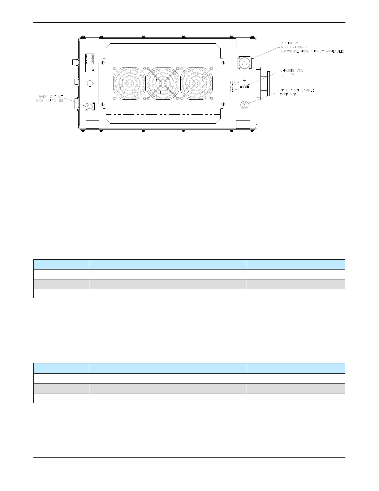
Figure 2-3: Bottom View, Compact Outdoor Amplifier
2.5.4 RF Output Sample Port (J3) [N-type (F)]
The RF Output Sample port, J3, is located on the bottom of the amplifier as shown in Figure 2
-3. This connector provides a -40 dBc sample of the amplifier’s output signal. It is a N-type
female connector.
2.5.5 Switch Port (J6) [MS3112E10-6S]
When used in a 1:1 redundant system, the waveguide switch must be connected to the switch
port of each amplifier (MS3112E10-6S). See Table 2-5.
Table 2-5 Switch Port (J6) Pin-Outs
Pin # on J6 Connection Pin # on J6 Connection
A N/C D N/C
B N/C E POS 2
C +28 VDC F POS 1
2.5.6 15 VDC Output Port (J8) [MS3112E10-6S]
The 15 VDC Output, J8, is located on the bottom side of the amplifier as shown in Figure 2-3.
This provides +15 VDC and up to 1 Amp current to any external equipment. It is a 6-pin
MS-type connector. See Table 2-6.
Table 2-6: +15 VDC Output Port (J8) Pin-Outs
Pin # on J8 Connection Pin # on J8 Connection
A EXTERNAL FAULT IN D GND
B FAULT PULLUP E +15V EXTERNAL
C +15V LNA F GND
2.5.7 Chassis Ground Terminal
A Chassis ground terminal is provided on the bottom side of the amplifier. A ¼ - 20 threaded
terminal is provided for equipment grounding.
Operations Manual, HPA2, Compact Outdoor SSPA 205486 REV F 15
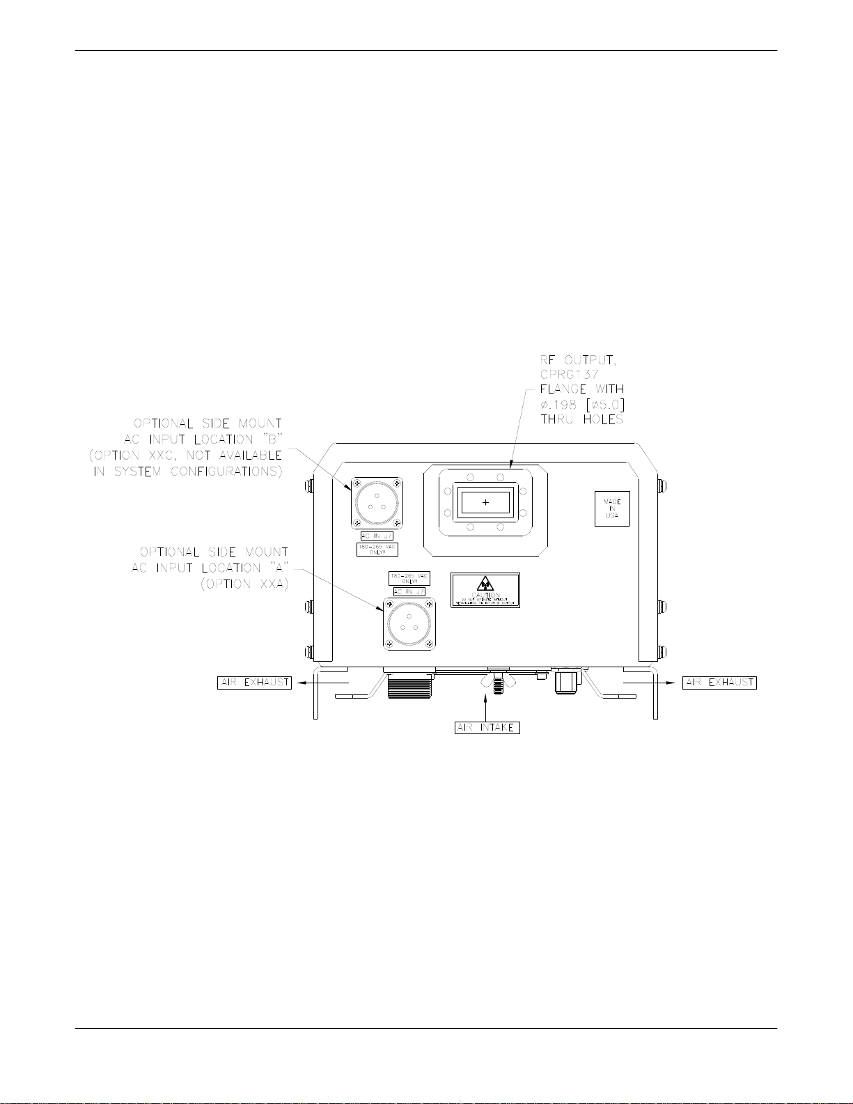
2.5.8 AC Input (J7)
The AC Input connector, J7, is located on the bottom side of the Compact Outdoor Amplifier
package. There are also two alternate placements for this connector on the RF Output end of
the amplifier as shown in Figure 2-4. This connector is a 3-pin circular connector, MS3102E20
-3P. The mating connector (MS3106E20-3S) is shipped with the unit. The pin out for this connector is given in Table 2-1.
2.5.9 RF Output (J2)
The RF Output is brought out through waveguide in the Compact Outdoor Amplifier. Figure
2-4 shows the output of a C-Band Compact Outdoor Amplifier. The Ku-Band amplifiers have a
WR75 grooved flange, while the C-Band and X-Band amplifiers have CPR style grooved
flanges (CPRG-137 for C-Band; CPRG-112 for X-Band). Ka-Band amplifiers utilize a WR28
grooved flange. S-Band units are fitted with Type N (F) connectors at the RF Output.
RF OUT
J2
Figure 2-4: RF Output Side of C Band Compact Outdoor SSPA
An isolator is provided at the output flange with a termination capable of handling full reflected
output power.
2.6 Airflow
The air intake and exhaust are both located on the bottom side of the amplifier. The intake is
brought through three fans while the exhaust is along the two rows of heat sink fins as seen in
Figure 2-4. A minimum clearance of 6 inches (152 mm) should be maintained between
the fans and any surface during operation. This will ensure that there is no forced
re-circulation of airflow from exhaust to intake. The Compact Outdoor SSPA should NEVER
be mounted with the fans facing up.
16 205486 REV F Operations Manual, HPA2, Compact Outdoor SSPA
2.7 Fiber-Optic Option
The Compact Outdoor Solid State Power Amplifier is available with an external fiber-optic
conversion box. This configuration requires the addition of a 1RU RCPF-1000 Fiber Optic
Control Panel. The Fiber-Optic Option is not available in S-Band units.
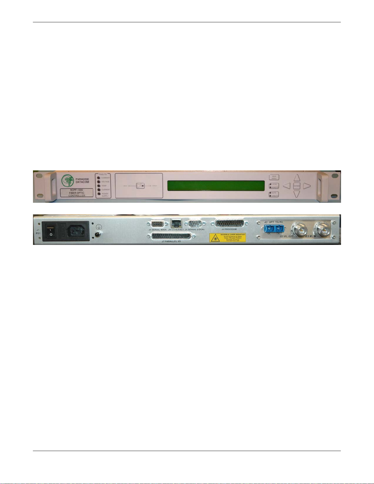
2.7.1 RCPF-1000 Fiber Optic Controller
The RCPF-1000 Fiber Optic Controller provides easy remote monitor and control of the Compact Outdoor SSPA with integral or external fiber-optic interface. Control of the RCPF-1000
can be handled through front panel operation or remotely via parallel or serial communication
to a remote computer running Paradise Datacom’s Universal M&C software.
The RCPF-1000 front panel includes 10 LEDs that indicate the internal state of the Compact
Outdoor SSPA. Five fault condition LEDs on the left side of the front panel indicate any SSPA
major faults, in addition to a summary fault state.
Figure 2-5: RCPF-1000 front, rear panels
A 2 line by 40 character LCD provides an extremely user friendly interface. Virtually all of the
controller’s setup and adjustments are accessible from the LCD. Four navigation buttons and
a separate Enter key allow the user to navigate the firmware menu on the LCD. Separate buttons have been provided for frequently used functions. A range of RF hardware options is offered to meet specific system requirements.
The rear panel features ports for Serial Main (J4), Serial Local (J5) and Parallel I/O connections, as well as N-type connectors for L-Band Tx and Rx paths, and FC/APC connectors for
Fiber Tx and Rx paths.
A complete description of the operation of the RCPF-1000 Fiber Optics Controller can be
found in its operations manual, Paradise Datacom document number 204640.
Operations Manual, HPA2, Compact Outdoor SSPA 205486 REV F 17
2.7.2 External L-Band to Fiber Interface
The External L-Band to Fiber Interface is a machined aluminum watertight enclosure, with
N-type connectors for L-Band RX and TX and fiber-optic connectors for the Fiber TX and RX
signals. The enclosure is powered via a +15 VDC Input port connected to a Compact Outdoor
SSPA’s 15VDC Output port (J8). An outline drawing of the enclosure is shown in Figure 2-6.
MODEL: XXXXXXXXXXXX
S/N: XXXX
P/N: LXXXXXX-X
Figure 2-6: Outline Drawing, External L-Band to fiber interface
The OFM-1000 external interface allows connection
between a Paradise Datacom Compact Outdoor
SSPA with integrated Block Up Converter and a
RCPF-1000 Fiber-Optic Control Panel via a fiber-optic
cable run.
Figure 2-8 shows a block diagram of a Compact
Outdoor SSPA with an external L-Band to fiber
enclosure connected to a RCPF-1000 controller.
Figure 2-7: OFM-1000
Figure 2-9 shows an example of a transceiver system utilizing an Evolution Series L-Band
modem, an RCPF-1000 fiber-optic controller, an external fiber to L-Band converter and a
Compact Outdoor SSPA with integral ZBUC. This example allow an optional connection to a
remote PC via RS-485, RS-232 or 10Base-T Ethernet connection.
18 205486 REV F Operations Manual, HPA2, Compact Outdoor SSPA
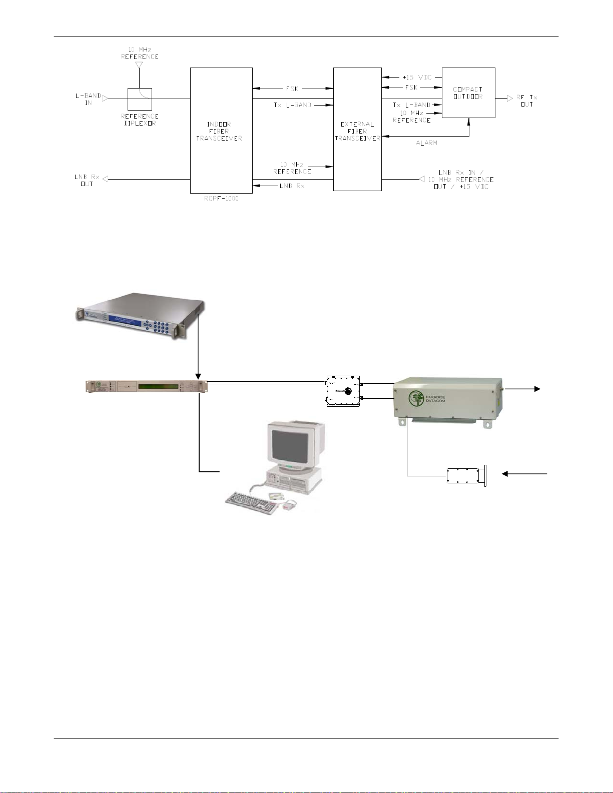
Figure 2-8: Block Diagram, Compact Outdoor with external fiber transceiver
EVOLUTION SERIES L-BAND MODEM
RCPF-1000
FIBER OPTIC CONTROLLER
RS-485 / RS-232 /
COAX
DATA
10Base-T Ethernet
FIBER OPTIC LINK
CARRIES FSK
CONTROL PLUS
OTHER SIGNALS
OPTIONAL PC
CONTROL
OFM-1000
FIBER TO L-BAND
CONVERTER
PC
COAX
COMPACT OUTDOOR SSPA
WITH INTEGRAL ZBUC
COAX
LNB
RF OUT
RF IN
Figure 2-9: System example, SSPA with External Fiber to L-Band Converter
Operations Manual, HPA2, Compact Outdoor SSPA 205486 REV F 19

2.8 Unit Weights
The Compact Outdoor SSPA is available in a variety of frequency bands and power levels,
and have a multitude of options which makes each unit weigh slightly different from another.
The following chart, Table 2-7, outlines the weights for the most common power levels of
Compact Outdoor SSPA.
Table 2-7: Compact Outdoor SSPA Weights
Band Model
HPAC2030AC... 36.5 (16.6) +1.7 (+0.8) N/A
HPAC2040AC... 36.5 (16.6) +1.7 (+0.8) N/A
HPAC2050AC... 36.5 (16.6) +1.7 (+0.8) N/A
C-Band
Ku-Band
X-Band
S-Band
Band
Ka-
HPAC2075AC... 36.5 (16.6) +1.7 (+0.8) N/A
HPAC2100AC... 36.8 (16.7) +1.7 (+0.8) N/A
HPAC2140AC... 37.0 (16.8) +1.7 (+0.8) +1.9 (+0.9)
HPAC2200AC... 37.8 (17.2) +1.7 (+0.8) +1.2 (+0.6)
HPAC2250AC... 45.4 (20.6) +1.7 (+0.8) +1.2 (+0.6)
HPAC2300AC... 46.9 (21.3) +1.7 (+0.8) N/A
HPAK2010AC... 35.1 (16.0) +1.7 (+0.8) N/A
HPAK2020AC... 35.1 (16.0) +1.7 (+0.8) N/A
HPAK2025AC... 35.1 (16.0) +1.7 (+0.8) N/A
HPAK2035AC... 35.1 (16.0) +1.7 (+0.8) N/A
HPAK2040AC... 35.3 (16.1) +1.7 (+0.8) N/A
HPAK2050AC... 35.7 (16.2) +1.7 (+0.8) N/A
HPAK2070AC... 35.7 (16.2) +1.7 (+0.8) N/A
HPAK2100AC... 42.5 (19.3) +1.7 (+0.8) +1.2 (+0.6)
HPAK2125AC... 42.5 (19.3) +1.7 (+0.8) +1.2 (+0.6)
HPAX2060AC... 46.3 (21.1) +1.7 (+0.8) N/A
HPAX2075AC... 46.7 (21.2) +1.7 (+0.8) N/A
HPAX2100AC... 46.7 (21.2) +1.7 (+0.8) N/A
HPAX2140AC... 47.5 (21.6) +1.7 (+0.8) +1.2 (+0.6)
HPAX2200AC... 54.9 (25.0) +1.7 (+0.8) +1.2 (+0.6)
HPAX2250AC... 56.4 (25.6) +1.7 (+0.8) N/A
HPAS2050AC... 36.0 (16.4) N/A N/A
HPAS2100AC... 36.0 (16.4) N/A N/A
HPAS2200AC... 44.0 (20.0) N/A N/A
HPAS2300AC... 44.0 (20.0) N/A N/A
HPAKA020AC… 44.3 (20.2) +1.7 (+0.8) N/A
HPAKA040AC... 44.3 (20.2) +1.7 (+0.8) N/A
Base Weight
lbs (kg)
With zBUC
lbs (kg)
With 110 VAC Option
lbs (kg)
20 205486 REV F Operations Manual, HPA2, Compact Outdoor SSPA
2.9 Compact Outdoor Mounting Kit Installation
These instructions outline how to install a single Paradise Datacom Compact Outdoor SSPA
unit onto an antenna boom using a Universal Compact Outdoor Mounting Kit. This kit allows
installation of the Compact Outdoor SSPA on antenna booms up to 10” thick.
2.9.1 Safety Considerations
These instructions are designed to be used by a single operator. As such, several safety issues should be kept in mind during the installation.
1. The Paradise Datacom Compact Outdoor SSPA unit weighs approximately 36 lbs.,
and should be handled with care to avoid scratching the exterior coating and compromising the unit’s corrosion resistance.
2. All bolts should be torqued down to within reasonable limits to avoid stripping the
threads.
3. The section of antenna boom the unit is to be mounted on should be straight, dry, and
free from corrosion or defects.
2.9.2 Inspection
On receiving the Universal Compact Outdoor Mounting Kit, inspect the contents to ensure all
parts are present. The kit should contain all items shown in Table 2-8.
Table 2-8: Compact Outdoor SSPA Mounting Kit
Item # Qty Description Part No.
1 4 Bracket, Mounting L201394-1
2 4 Uni-Strut, 13.5” Lengths L201393-1
3* 4 1/2”-13 All Thread Stud, SS 188FTS 8-11 or -15
4 4 1/2” Lock Washer 50LW188
5 16 Nut, Hex, 1/2”-13 1/2-13 Nut
6 16 Washer, Flat, Std. 1/2” MS15795-819
7 4 Bolt, Hex, 1/2”-13 x 1.25, SS MS35307-411
* Kits are supplied with two different All Thread lengths (11.0” or 15.0”) depending on the
installation. The 11-inch All Thread (part no. 188FTS 8-11) allows mounting on booms up to
6” diameter. The 15-inch All Thread (part no. 188FTS 8-15) allows mounting on booms up to
10” diameter.
Operations Manual, HPA2, Compact Outdoor SSPA 205486 REV F 21
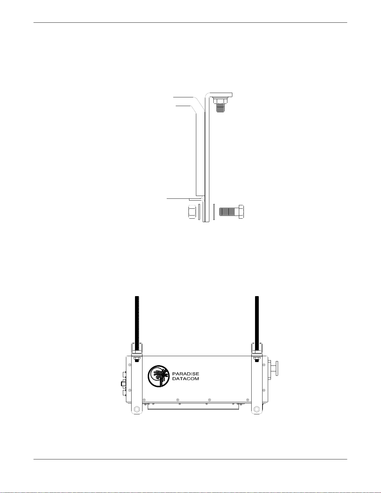
2.9.3 Installation
1. Locate the mounting studs on the bottom of the Compact Outdoor SSPA unit. Using a ½”
bolt, two flat washers, and a ½” nut, firmly bolt one mounting bracket to each mounting
stud, as shown in Figure 2-10. Be sure each bracket is vertical, and the top flange of the
mounting bracket points away from the unit.
Figure 2-10: Bolt Mounting Bracket to Unit
2. Place one piece of Uni-Strut (open channel up) at each end of the CO unit, across the
flanges of the mounting brackets, lining up the holes. For each All-Thread stud, run on a
½” nut approximately 1” from the rod end. Slip on a lock washer, and thread the short
end of the stud through the Uni-strut and mounting flange. Secure firmly in place with a
flat washer and nut. The unit should now look as shown in Figure 2-11.
Figure 2-11: Unit Ready for Boom Installation
22 205486 REV F Operations Manual, HPA2, Compact Outdoor SSPA
3. Bring the unit up tight under the boom (with the long axes parallel), sliding the All-Thread
studs past the sides of the boom to show above the boom top. Place the remaining pieces
of Uni-strut (open channel down) across the boom, onto the protruding All-Thread stud
ends. Secure firmly with a flat washer and ½” nut on each of the four All-Thread stud
ends. Looking from the end of the boom, the mounted unit should look as shown in Figure
2-12.
Figure 2-12: Compact Outdoor Mounting Completed
4. Connect the Compact Outdoor SSPA unit’s power source, RF Input and RF Output as
directed elsewhere in this manual.
DO NOT APPLY POWER TO THE COMPACT OUTDOOR UNIT BEFORE
TERMINATING THE RF OUTPUT CONNECTOR.
Operations Manual, HPA2, Compact Outdoor SSPA 205486 REV F 23
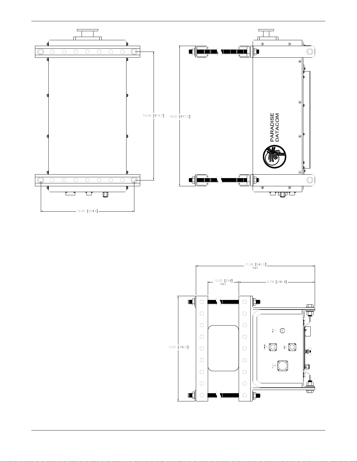
ANTENNA
BOOM
Figure 2-13: Outline Drawing, Compact Outdoor Mounting Kit
24 205486 REV F Operations Manual, HPA2, Compact Outdoor SSPA

Section 3: Operation
3.0 Introduction
This section of the manual describes the operation of the Compact Outdoor Solid State Power
Amplifier. The Compact Outdoor unit has been designed for maximum flexibility in amplifier
system configuration. It has a full compliment of parallel I/O monitor and control signals as
well as serial I/O capability using a PC and host communication software from Paradise
Datacom LLC. Table 3-1 shows the pin out of the Monitor and Control connector, J4.
3.1 RF Input (J1)
The RF Input signal is applied to J1. The Compact Outdoor SSPA has a default maximum
nominal gain of 75 dB minimum. Therefore the maximum input signal required to saturate the
amplifier can be calculated as:
Input Power = P
For example, if a 50 W Ku Band Compact Outdoor amplifier is used in a system it has a
P
= 47.0 dBm. Therefore the maximum input power should be limited to -28 dBm. Slightly
sat
higher input power levels will not damage the amplifier but will result in higher levels of
distortion in the output signal.
WARNING! The maximum input level should be limited to +15 dBm to
avoid damaging the amplifier.
3.2 RF Output (J2)
The amplifier’s output is taken from the waveguide port, J2. Caution should be observed here
to make sure that the antenna or a suitable termination is connected to this port before
operating the amplifier. The amplifier is protected against full reflection but dangerous levels
of microwave energy can be present at this port.
WARNING! Never look directly into the RF output waveguide.
3.3 Amplifier Enable (Mute/Unmute) (J4)
The Compact Outdoor Amplifier has no on/off switch or circuit breaker in the AC Input path.
As soon as AC power is applied to J7, the unit’s power supplies and microcontroller are
enabled. The operator will be able to observe the forced convection cooling fans running.
However, the internal amplifier module is disabled until the Mute Line Input (J4 – Pin B) is
pulled to Ground (J4 – Pin V).
If it is desired to have the RF enabled every time the AC input is applied, a permanent
connection can be made from J4-Pin B and Pin V.
- 75 dB
sat
Operations Manual, HPA2, Compact Outdoor SSPA 205486 REV F 25
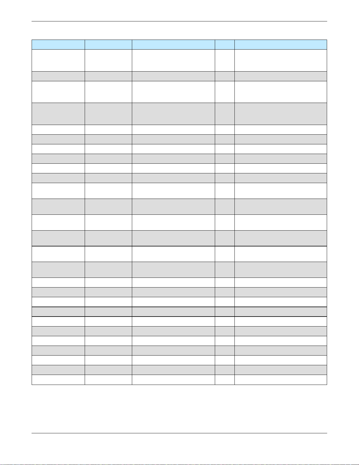
Table 3-1: Monitor & Control Connector, J4
Signal Type Function Pin Notes
Mute Input Closure to Ground Disables DC Power to SSPA B Unit Powers up Muted, This line must
be pulled to ground (V or d) to enable
amplifier
Auxiliary Input Closure to Ground Auxiliary Fault Input P
Summary Alarm Form C Relay Closed on Fault
Common
Open on Fault
Auxiliary Alarm Form C Relay Closed on Fault
Common
Open on Fault
Open Collector High on Fault W Reserved
Auxiliary Alarm Open Collector High on Fault G Requires external pull-up
Voltage Alarm Open Collector High on Fault H Requires external pull-up
Current Alarm Open Collector High on Fault J Requires external pull-up
Temperature Alarm Open Collector High on Fault X Requires external pull-up
Spare Fault Open Collector High on Fault S Requires external pull-up
RF Power Detector Analog Output Relative Indication of RF Output
Power
Gain Adjust Input Analog Input Adjusts Amplifier Gain over 20dB
range
Block Up Converter
Alarm
RS232 / RS485
Select
RS 485 TX- or
RS232 OUT
RS 485 RX- or
RS232 IN
RS 485 TX+ Serial TX Output Serial Link Data Port T
RS 485 RX+ Serial RX Input Serial Link Data Port U
GND Signal Ground Common Signal Return V, d
Baud Select 0 Closure to Gnd Select Baud Rate & Protocol j Refer to Appendix C
Baud Select 1 Closure to Gnd Select Baud Rate & Protocol e Refer to Appendix C
PGM Switch Flash Firmware Port g Reserved for Programming
PGM CLK Flash Firmware Port c Reserved for Programming
PGM-Sout Flash Firmware Port K Reserved for Programming
PGM-Sin Flash Firmware Port Y Reserved for Programming
PGM +5V Flash Firmware Port h Reserved for Programming
PGM Enable Flash Firmware Port C Reserved for Programming
Open Collector High on Fault f Requires external pull-up
Closure to Ground Selects Serial Communication D Default is RS 485; pull to ground (V)
Serial TX Output Serial Link Data Port E
Serial RX Input Serial Link Data Port F 9600 default Baud Rate
L
a
b
N
Z
M
R +4.0 vdc at Psat
A 2.5 vdc = Max Gain 75dB
L-a : normally open
a-b : normally closed
N-Z : normally open
Z-M: normally closed
0.5 vdc = Min Gain 55dB
to enable RS 232
26 205486 REV F Operations Manual, HPA2, Compact Outdoor SSPA

3.4 Alarms (J4)
A variety of alarm signals are present at the M&C connector, J4. Both Form-C relays and
open collector outputs are available. An amplifier summary alarm is available in both Form C
relay and open collector output. Detailed internal faults are available in open collector form
and include: voltage, current, and over-temperature.
3.4.1 Summary Alarm (J4) Form C Contacts
The Summary Alarm is accessible in both Form C relay and open collector format. The form
C relay is “energized” under normal operating conditions and “deenergized” when a fault
condition exists.
3.4.2 Auxiliary Alarm (J4) Form C Contacts
The Auxiliary Alarm relay is an end user alarm that can be used to signal an alarm condition
that is dependent on the state of the Auxiliary Input (J4-Pin P).
The Auxiliary Input is a contact closure to ground. When this input is pulled to ground the
Auxiliary Alarm relay is energized (Normal State). When the Auxiliary Input is open circuited
the Auxiliary Alarm relay is de-energized (Alarm State).
One example usage of the Auxiliary Alarm is that it could be used to signal one of the detail
alarms (voltage, current, or temperature) by connecting the appropriate open collector alarm
output to the Auxiliary Input. This programs the Auxiliary Alarm relay to be either a voltage,
current, or temperatue Form C relay alarm.
3.4.3 Open Collector Alarm Outputs (J4)
The open collector alarm outputs will require external pull-up resistors (unless connected to
the Auxiliary Input). They are capable of sinking up to 20mA current at 30 VDC. The open
collector outputs are pulled to ground under normal operating conditions and switch to high
impedance state during an alarm condition.
Auxiliary Alarm: follows state of Auxiliary Input as described above
Voltage Alarm: high when amplifier’s internal regulator voltage falls below its
acceptable level
Current Alarm: high when the amplifier’s operating current falls below its acceptable
level
Temperature Alarm: high when the amplifier’s baseplate temperature rises above its
acceptable threshold of 90°C. A 5°C hysteresis window exists in the temperature
alarm.
Spare Alarm: high when the phase locked local oscillator’s lock alarm is triggered
Operations Manual, HPA2, Compact Outdoor SSPA 205486 REV F 27

3.5 RF Power Detector (J4)
The RF Power Detector is an analog output voltage that is proportional to the RF output
power. The maximum output voltage is 4.0 VDC which corresponds to the maximum
(saturated) output power from the amplifier. This detected voltage is useful over a 20 dB
range of output power.
3.6 RF Output Sample (J3)
An RF sample of the amplifier’s output is available at J3. This is a -40 dBc coupled sample of
the amplifier’s output signal.
3.7 Gain Adjust Input (J4)
The Gain Adjust Input allows an analog voltage that is applied between (J4 – Pin A) and
Ground (J4 – Pin V) to control the gain of the amplifier. The gain is adjustable over a 20 dB
range with 0.1 dB resolution. The applied voltage is directly proportional to amplifier gain.
2.5 VDC = Maximum Gain: 75 dB
0.5 VDC = Minimum Gain: 55 dB
The Compact Outdoor SSPA is factory default to have maximum gain with no analog gain
adjust. The gain adjustment must be enabled by running the setup program from a host PC.
This prohibits any accidental gain adjustments that may occur from unintentional analog
voltages that may be present on the Gain Adjust Control J4-Pin A.
The gain is also adjustable using a host PC and the supplied Paradise Datacom Monitor and
Control program. See the Serial I/O Section for details on Serial Control.
3.8 Serial I/O Control (J4)
For serial data control of the Compact Outdoor SSPA, a Windows-based Monitor &Control
program is supplied with the amplifier that allows all of the control and alarm functionality over
a serial communication link.
Both RS232 and RS485 can be used to communicate with the amplifier. The amplifier default
is to operate on RS485 but can easily be set to RS232 by pulling the RS232/RS485 Select
line low. This is done by connecting J4-Pin D to J4-Pin V.
Communication Links using RS232 are typically good up to 30 ft. (9 m) in length. Installations
exceeding this length can use the RS485 mode which will allow serial control up to 4000 ft.
(1200 m).
28 205486 REV F Operations Manual, HPA2, Compact Outdoor SSPA
The Compact Outdoor Amplifier is supplied with a cable in which this connection is already
made. This allows the user to quickly setup the amplifier and verify its operation. The other
side of the cable has a 9-Pin female D connector that mates with most notebook and desktop
personal computers.
3.9 Compact Outdoor Amplifier Quick Start Guide
● Unpack the amplifier and connect the RF Input and RF Output as described earlier in this
manual.
● Connect the AC input power to connector J7.
● Connect the supplied “Quick-Start” Control Cable (201433) from port J4 to an available
Comm Port on your computer. The cable schematic is shown in Appendix A.
● Install the Windows-based Paradise Datacom Universal Monitor and Control Program
from the supplied CD.
● Run the Paradise Datacom Universal Monitor and Control Program from the Programs
Menu of your PC.
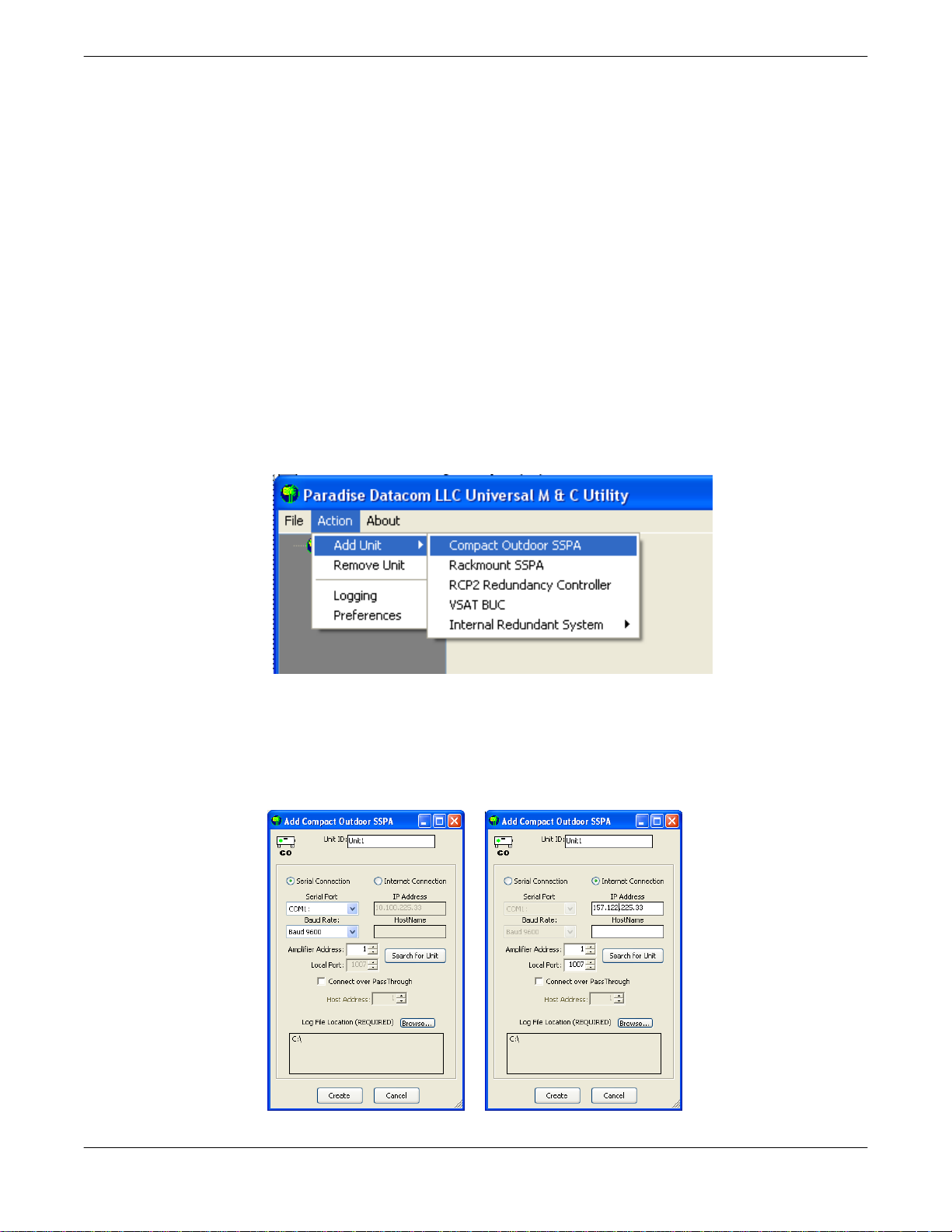
● Select [Action] [Add Unit] from the main menu of the Universal M&C Program and
select [Compact Outdoor SSPA] from the menu choices. See Figure 3-1.
Figure 3-1: Universal M&C Add Unit menu
● A new dialog window will open (see Figure 3-2). Enter the following information where
applicable: Unit ID, Serial Port for communication, Baud Rate. Only serial connections are
available with a standalone Compact Outdoor SSPA. The addition of a Remote Control
unit (RCP2-1000-CO) allows connection via Internet Protocol.
Serial connection ► ◄ Internet connection
Figure 3-2: Add Compact Outdoor SSPA window, via Serial (left) or Internet (right)
Operations Manual, HPA2, Compact Outdoor SSPA 205486 REV F 29
● Specify the unit’s Address in the Amplifier Address box. If you don’t know the address of
the unit you may search for it. Be aware that this search feature is only useful when you
have only one unit connected to your PC at a time.
● If you wish to change the log file location, click on the [Browse] button and navigate to the
desired location. See Section 3.9.3 for more information about the log file.
● Click on the [Create] button to generate the operation window for this unit.
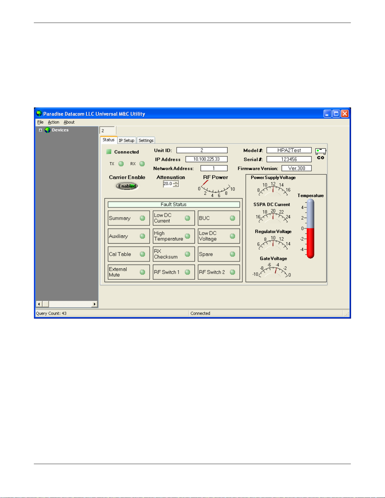
● The M&C “Operation” window will be displayed as in Figure 3-3, and includes tabs for the
unit Status window, Settings and IP Setup (where applicable).
Figure 3-3: Universal M&C Status Window
3.9.1 Status Window
The Status Window is the main monitoring display, and shows the the current conditions (or
state) of the Compact Outdoor SSPA. In addition, the status screen allows for Mute/Unmute
of the carrier and manual adjustment of the on-board Attenuator for gain control.
Upon connection with a unit, the M&C application obtains and displays the unit ID, the
amplifier’s model number and serial number. The SSPA module’s firmware version number is
also displayed here for convenience.
The unit’s network address and serial COM or IP address are also listed, which can be helpful
in optimizing serial communications.
30 205486 REV F Operations Manual, HPA2, Compact Outdoor SSPA

3.9.1.1 Signal Indicators
Three rows of LEDs show the connection status of the connected amplifier. Top-most is an
indicator that displays a green LED when Connected, or a red LED when Disconnected.
Immediately below are two LEDs for the TX and RX paths. The LED in the third row displays
the mute state (Carrier Enable). This is actually a toggle which allows the user to Enable or
Mute the amplifier.
3.9.1.2 Fault Status Indicators
The Fault Status frame in the lower left side of the Status Window contains 12 SSPA fault
lights that correspond to :
BUC
Converter fault)
regulator)
Summary Alarm
Auxiliary
Low DC Current
(SSPA Module current)
High Temperature
(SSPA Module Baseplate)
(Optional Block Up
Low DC Voltage
(SSPA internal voltage
Calibration Table RX Checksum Spare
External Mute RF Switch 1 RF Switch 2
Summary Alarm: The Summary Alarm is simply a logical ‘OR’ of any of the alarm indicators.
Low DC Current Alarm: The Current Fault is factory preset to alarm if the SSPA module
current falls below 80% of its nominal value.
BUC Alarm: The BUC fault is only active in units that are supplied with an optional L-Band
Block Up Converter module. If the Up Converter’s phase locked local oscillator loses lock, a
BUC alarm is set and the amplifier is muted so that spurious RF can not be transmitted to the
satellite.
Auxiliary & Spare Alarms: The Auxiliary and Spare Alarms are configurable from the
Settings Window. See Section 3.9.2.
High Temperature Alarm: The Temperature Fault indicator is factory preset to alarm at 80°
C. The amplifier will continue to operate up to 90°C. Beyond 90°C the DC power will be
interrupted to the SSPA module. This measure will protect the sensitive microwave transistors
from catastrophic failure. The fans and monitor and control circuitry will continue to operate
normally. This function has approximately a 5°C hysteresis window which will allow the
amplifier to re-enable itself when the ambient temperature is reduced by 5°C. The
Temperature Alarm is intended to warn the operator of possible fan problems and eventual
amplifier shutdown.
Low DC Voltage Alarm: The Voltage Alarm is factory preset to alarm if the SSPA module
current falls below 80% of its nominal value.
Calibration Table: The Cal Table Alarm is used under initial test at the factory.
Operations Manual, HPA2, Compact Outdoor SSPA 205486 REV F 31

RX Checksum Alarm: The RX Checksum Alarm indicates when an invalid checksum byte is
communicated to the unit.
External Mute Alarm: The External (Ext) Mute line gives an indication via the M&C screen
that the SSPA has been externally muted by J4-Pin B. This external mute alarm can be
configured to trigger a summary alarm if desired. The factory default is to signal a External
Mute fault but no Summary Alarm.
RF Switch Alarms: The RF Switch 1 Alarm is only active if a 1:1 Redundant System has
been configured in the M&C program. The RF Switch 2 Alarm is only active is a 1:2
Redundant System has been configured. These configuration are covered in Section 7, the
Redundant System Concepts description.
All of the above alarms, with the exception of the RF Switch and External Mute Alarms, are
available as open collector outputs and Form C relays on the J4 parallel interface.
3.9.1.3 Voltage, Current and Temperature Display
On the right side of the Status window there is a thermometer display that reports the present
baseplate temperature of the amplifier. The baseplate temperature typically experiences a 20
to 30 degree rise above ambient on the highest power Compact Outdoor Amplifiers and 15 to
20 degree rise on lower power units.
To the left of the thermometer display are several indicators that show various operating
conditions of the Compact Outdoor Amplifier in real time. These indicators are helpful for any
diagnostic proceedures. Among the horizontal indicators include:
• Power Supply Voltage
• SSPA DC Current
• Regulator Voltage
• Gate Voltage
The Power Supply voltage monitors the primary 12 volt power supply output. SSPA Current is
the total current drawn by the microwave transistors. Regulator Voltage is the DC voltage of
the drain circuitry that feeds the GaAs transistors. The Gate Voltage indicator monitors the
DC voltage of the gate circuitry of the microwave GaAs transistors. These indicators provide
direct access to the active device operating characteristics.
3.9.1.4 Gain Adjustment
The Gain Attenuation Control is located above the Fault Condition Indicators and to the right
of the Carrier Enable status. The gain can be adjusted by setting the Attenuation Control. An
Attenuation Control of 0 dB is the maximum gain (75 dB) setting on the amplifier. By setting
the Attenuation Control to 20 dB; the gain is set to (55 dB). The Attenuation Control can be
varied using the control knob or the forward/reverse buttons.
Note the illuminated PC Control button inside the Attenuation Control frame. This control
allows the gain adjustment function to be assigned to the analog input voltage (J4-Pin A). The
gain adjustment control must be either under PC control or analog voltage control; it cannot
be both.
32 205486 REV F Operations Manual, HPA2, Compact Outdoor SSPA

3.9.1.5 RF Power Indicator
The RF Power indicator is the vertical meter in the central part of the Operation window. This
indicator reports the approximate output power of the amplifier. It uses the voltage from the
RF Power Detector to determine a corresponding power level in dBm. The accuracy of the
power indicator is ± 1 dB at the mid-point of the specified band, with a single CW or QPSK
carrier.
3.9.1.6 Carrier Enable
This button toggles between the “Enabled” and “Muted” conditions. This software mute
requires 70 msec maximum (30 msec typical) to take effect.
3.9.2 Settings Window
Figure 3-4 shows the ‘Settings’ window of the Paradise Datacom Universal Monitor & Control
Software. The ‘Settings’ window contains many of the global settings that are available in the
SSPA.
Figure 3-4: Universal M&C Settings Window
Operations Manual, HPA2, Compact Outdoor SSPA 205486 REV F 33

3.9.2.1 Power Up Settings
The Compact Outdoor amplifier will power up with the “last-state” settings before the unit was
powered down. Whatever attenuation setting or mute state the amplifier was in when
powered down will be the restored settings when the amplifier is powered back on.
Operation Mode: Select between stand alone (single unit) or redundancy mode
of operation.
Hierarchical Address: Identifies each amplifier in a redundant system as HPA
1 or HPA 2.
Redundant Startup State: Selects whether the unit should start up as the on
-line amplifier or the standby amplifier.
Mute State: Determines if the unit should start up muted (transmit disabled) or
mute clear (transmit enabled).
Gain Control: Select between serial communication control of the unit’s gain or
analog voltage gain control via J4.
Protocol Select: Selects between the standard string protocol of Section 9 or
older generation binary based protocol.
Baud Rate: Sets the baud rate of the unit. The supported baud rates include:
2400, 4800, 9600, 19200, and 38400 baud. The factory default baud rate is
9600.
Standby Mode: Selects between Hot and Cold standby mode for units in
redundant systems.
BUC Reference: Selects between an Internal or External reference for an
optional block up coverter integrated with the unit, or allows the unit to Auto
-switch between Internal and External reference.
Fault Thresholds: Allows the user to set the limit for triggering the unit’s
Current Fault or High Temperature Fault.
Low Current Fault Threshold: Range is 0 to 102.3, with each 0.1 equal
to 97.75 mA.
High Temperature Alarm Threshold: Range is 0 to 125 °C.
34 205486 REV F Operations Manual, HPA2, Compact Outdoor SSPA

Fault Setup: This feature allows the user to set the Spare Fault Trigger using
the Spare Fault Wizard.
Click on the Spare Fault Wizard button, which opens a new window. See Figure
3-5. Select between the following fault triggers: LNB Current, Gate Voltage,
Regulator Voltage, Power Supply Voltage, SSPA Current, External Mute, or
None. Set the range of maximum and minimum thresholds that would trigger the
selected fault, and configure the fault handling via a pull-down menu. Click [OK]
to set the fault trigger for the Spare Fault.
Figure 3-5: Spare Fault Wizard
The user may also adjust the Spare, Auxiliary and BUC Fault Status and
Handling via the appropriate pull-down menus on the Settings Window.
Spare/Auxiliary/BUC Fault Handling: Selects whether the associated
fault should be a major or minor fault, and whether the fault should mute
the unit. A minor fault will trigger a Spare/Auxiliary/BUC Fault alarm but
not trigger a Summary Fault. A major fault will trigger both an Spare/
Auxiliary/BUC Fault and a Summary Fault.
Auxiliary/BUC Fault Status: Determines if the associated fault input
should be ignored or enabled (either Logic High or Logic Low; or Logic ZState for Auxiliary Fault).
Attenuation Level: The Gain Adjustment of the unit is adjustable here. See
Section 3.9.1.4.
Unique Network Address: Sets a network address for the unit. Range is 0 to
255.
Operations Manual, HPA2, Compact Outdoor SSPA 205486 REV F 35

3.9.3 Universal M&C Preferences
The user can adjust certain preferences of the Universal Monitor and Control Software. See
Figure 3-6.
Figure 3-6: Preferences Window
Queries: Enable and adjust the interval that the software queries the unit. Note that if
queries are disabled, there will be no communication with the unit at startup.
Logs: Enable and adjust the interval that the software writes to the log. The log
location is determined during unit setup, with the default location set to the My
Documents folder. Each entry catalogs the RF Power Level and Temperature of the
unit. See Figure 3-7 for an example of a log entry.
Figure 3-7: Example, Log entry
TCP/IP: Select the Local UDP Port (the software must be restarted to take effect). Note
that each UDP address must be unique.
Appearance: Set the transparency of the M&C Windows.
Startup: Enable or disable auto-loading of the last device configuration.
36 205486 REV F Operations Manual, HPA2, Compact Outdoor SSPA

Section 4: Theory of Operation
4.0 Introduction
This section contains information on the theory of operation of the Compact Outdoor Solid
State Power Amplifier. This includes a discussion of the system block diagram, amplifier
module operation, and unique cooling system.
The Compact Outdoor Solid State Amplifier has been designed to be an extremely robust
microwave amplifier system. It is very well suited for environmentally demanding conditions
where reliability is paramount. At the heart of the amplifier system is a multifunction solid state
power amplifier (SSPA) module.
Proprietary thermal management techniques allow even the highest output power level
amplifiers to operate reliably in environments up to 60°C ambient temperature and 100%
relative humidity.
Figure 4-1 shows the block diagram of the amplifier system. As seen in the block diagram
there are five major active components:
1. EMI Filter and Transient Protection
2. Power Supply
3. Solid State Power Amplifier Module
4. Fan Boost Converter
5. Cooling System
Figure 4-1: Block Diagram, Compact Outdoor Amplifier
Operations Manual, HPA2, Compact Outdoor SSPA 205486 REV F 37

4.1 EMI Filter and Transient Protection
The EMI (Electro-magnetic Interference) Filter is a passive electronic device used to suppress
conducted interference present on any power or signal line. It may be used to suppress the
interference generated by the device itself as well as to suppress the interference generated
by other equipment to improve the immunity of a device to the EMI signals present within its
electromagnetic environment. The filter was designed with an added Metal Oxide Variable
resistor (MOV) to provide transient voltage and surge protection.
4.2 Power Supply
The Power Supply consists of one or two AC/DC Converters and a DC/DC Converter.
4.2.1 AC / DC Converter
The prime AC input power is delivered to a switching converter module that produces 300
VDC. Depending on the input power requirement of the amplifier, there may be one or two
AC/DC Converters present in the unit. These modules are auto-sensing, power factor
corrected front ends that have proven reliability and allow the amplifier system to operate over
a wide variety of input power conditions encountered around the world. A high current,
common mode filter is used on the input side of the converter module that reduces switching
components to very minimal levels.
4.2.2 DC / DC Converter
The DC/DC converter module is also a switched mode power supply that converts the 300
VDC to 12 VDC. This 12 VDC is the primary high current, DC voltage source that operates
the entire amplifier system.
4.3 Solid State Power Amplifier Module
The amplifier module is a unique high density, multifunction module. It not only contains all of
the RF signal amplification and distribution, but also is home to the microcontroller based
monitor and control circuitry. An extremely robust regulation and bias control board supplies
the power to the microwave GaAs FET devices. A separate microcontroller board provides
the M&C functions for the amplifier. Some of the features of this board include:
(3) Serial Ports
(1) Dedicated Flash Firmware Programming
(1) Ethernet Port for Host Communication
(1) Selectable RS232 / RS485 for Host Communication
(2) Form C Relays
Summary Alarm, Auxiliary Alarm
(5) Open Collector Outputs
Summary, Auxiliary, Voltage, Current, Temperature, Block Up Converter Faults
(2) Closure to Ground Inputs
Mute, Auxiliary Input
(8) 10 bit Analog Voltage Measurement Channels
38 205486 REV F Operations Manual, HPA2, Compact Outdoor SSPA

SSPA Module Current
Regulator Voltage
Power Supply Voltage
Negative 5v Gate Voltage
Optional Power Supply Temperature
RF Output Power Detector
Analog Gain Adjustment
(1) 10 bit D/A for SSPA Gain Adjustment / Temperature Compensation
20 dB gain adjustment with 0.1 dB resolution
(1) Very Accurate Digital Temperature Sensor
0.5 degree resolution within 1°C of SSPA module case temperature
4.4 Fan Boost Converter
The Fan Boost Converter is a separate DC/DC boost converter that produces a 24 VDC
source from the 12 VDC output of the main power supply. This voltage source is then used to
power the cooling system fans.
4.5 Cooling System
The Compact Outdoor Amplifier’s cooling system represents a landmark in microwave
telecommunication amplifiers. It is a unique system of heatsinks that have been computer
optimized to provide extremely efficient cooling of all of the system’s functional blocks. This
high efficiency cooling system is primarily responsible for the small overall package size and
reduced weight of the unit (as low as 36 lbs or 16.4 kg).
The cooling system is based on a forced convection technique in which the system fans
provide the air intake while the exhaust is brought out around the outer perimeter of the fans.
The fans are 103 CFM rated and operate into approximately 0.7 in. H2O back pressure.
Operations Manual, HPA2, Compact Outdoor SSPA 205486 REV F 39

THIS PAGE INTENTIONALLY LEFT BLANK
40 205486 REV F Operations Manual, HPA2, Compact Outdoor SSPA

Section 5: Performance Tests
5.0 Introduction
This section describes some of the standard RF tests performed on production amplifiers
before shipment. Where possible Paradise Datacom, LLC maintains computer automated RF
test stations to ensure a high level of accuracy and consistency to production amplifier
testing.
5.1 Gain and Gain Flatness
The amplifier gain is swept over the operating frequency range under small signal conditions
to confirm the minimum gain and gain flatness specifications. The entire Compact Outdoor
Amplifier is tested in a temperature chamber from -40°C to +55°C; and the gain is recorded.
5.2 P
The 1 dB Gain Compression Point is measured at discrete frequencies across the band to
characterize the output power over the operating frequency range. The P
minimum specification.
5.3 Input and Output Return Loss
The input and output return loss are measured in all production amplifiers. This is a measure
of how closely the amplifier is matched to its characteristic impedance. The input impedance
of the amplifier is a nominal 50 ohms while the output is matched to the waveguide complex
impedance.
5.4 Spurious
Spurious signals are undesirable byproducts of amplifiers caused by nonlinearities within the
amplifier and other system level components such as switch mode power supplies. These
unwanted signals cause signal management problems in system applications. Out of band
spurious signals cause interference to other pieces of equipment.
5.5 RF Sample Port
The RF Sample port is measured at discrete frequencies across the band and a calibration
label is placed near the type N connector on the bottom of the unit. The sample port is
approximately -40 dB down from the RF output. A label with the exact coupling ratio is
attached to the amplifier chassis.
1dB
is a guaranteed
1dB
Operations Manual, HPA2, Compact Outdoor SSPA 205486 REV F 41

5.6 Intermodulation Distortion
Intermodulation distortion is one of the most important characteristics of a solid state power
amplifier system. Satellite communication systems must comply to certain distortion levels
depending on the service involved. All production amplifiers are subjected to automated
intermod testing. This is based on a standard two-tone intermod test in which the intermod
level (IMD) is measured in dBc with respect the main tones and the highest third order
intermod products.
Satcom amplifiers are typically used in some ‘back-off’ condition. This is the operating point at
which the composite output power is ‘backed-off’ from the amplifier’s P
A curve of back-off vs. IMD level is especially useful in the selection of a power amplifier or
determining the proper output power setting in a Satcom system.
Paradise Datacom recognizes the importance of this back-off characteristic and provides a
plot of back-off Vs IMD from 1 dB to 10 dB back from the amplifier’s compression point.
Figure 5-1 shows a typical back-off curve from a production test set.
, compression point.
1dB
Figure 5-1: IMD vs. Backoff for a 50W Ku Band Compact Outdoor SSPA
42 205486 REV F Operations Manual, HPA2, Compact Outdoor SSPA

Section 6: Maintenance
6.0 Introduction
This section describes some of the standard maintenance practices that can be performed
on the Compact Outdoor Amplifier.
6.1 Cooling System Maintenance
It is recommended that the cooling system be checked at least once per month. This
involves visually inspecting the fan intakes to make sure that there is no obstructions over
the intake. The Windows-based M&C program can be used to check the amplifier base
plate temperature. The base plate temperature should normally not exceed a 30°C to 35°C
rise above the current outside ambient temperature. If the base plate temperature exceeds
this temperature rise, it is one indicator that the system’s airflow requires maintenance.
The heat sink fins in the exhaust path can be visually inspected for excessive dirt and
debris buildup. If it appears there is excessive debris in the heat sink; the fan tray can be
removed for easy cleaning. Failure to keep the fans and heat sink clear of debris will
void your warranty.
6.2 Fan Removal
It is recommended to remove prime AC power from the amplifier when the fan tray is being
removed. However, if necessary, the fan tray can be removed while the amplifier is
operating. Caution should be used to make sure that no clothing or fingers are caught in
the fan blades. Simply remove the four screws from the fan tray and the fan assembly can
be removed from the bottom of the amplifier assembly.
The fans are connected to their power source by weatherized in-line circular connectors. A
replacement fan with connector can be provided for replacement. While the fan tray is
removed, the heat sink fins can be cleaned by spraying compressed air throughout the
finned area. A can of dust remover spray such as that which is found at a computer or
electronics shop will work fine.
Figure 6-1: Fan Removal from Amplifier Assembly
Operations Manual, HPA2, Compact Outdoor SSPA 205486 REV F 43

6.2.1 Fan Replacement
Older models of the Compact Outdoor SSPA were fitted with a 2-fan cooling fan assembly.
The newer models utilize a 3-fan cooling fan assembly.
While the fan interface connectors for the two-fan and three-fan tray assemblies are identical,
they should not be used interchangeably.
If your Compact Outdoor SSPA was shipped from the factory with the three-fan air intake tray,
any maintenance requiring replacement of the fans should only use the three fan kit (L205192
-1). The three fan kit requires 12VDC directly from the buss bar and draws 5.9A (70W).
If your Compact Outdoor SSPA was shipped from the factory with the two-fan air intake tray,
any maintenance requiring replacement of the fans should only use fan kit L201814-1. This kit
replaces one fan on the fan tray assembly. The two fan kit requires 28VDC from the booster
circuit card assembly and draws 0.7A (19W).
Note: Failure to use the proper fan tray will cause damage to your amplifier!
It is possible to modify an older Compact Outdoor SSPA to be fitted with a 3-fan cooling fan
assembly in place of a 2-fan assembly. This should be done by an authorized Paradise
Datacom technician, using the procedure outlined in drawing number 206573.
6.3 Connector Weatherproofing
As a precaution against water intrusion, all cable connections should be wrapped with
weather-resistant electrical tape, provided with
the unit. Make sure each connector is clean and
dry before applying the electrical tape.
Apply the electrical tape to all MS connectors
and N-type connectors . Starting at the cable
end, wrap the weather-resistant electrical tape
around the connector, overlapping each turn by
half the width of the tape. Continue wrapping
until the connection mating point is enveloped.
Wrap an extra turn around the base of the
connector. Press and smooth the tape with your
fingers to form a good seal. The tape surface
should be uniform in appearance with no visible
gaps or protrusions. See Figure 6-2.
Figure 6-2: MS connector, wrapped with
weather-resistant self-sealing tape
44 205486 REV F Operations Manual, HPA2, Compact Outdoor SSPA

Section 7: Redundant System Operation
7.0 Redundant System Concepts
The Compact Outdoor Amplifier is capable of operating in a variety of redundant system
configurations. These include 1:1 and 1:2 as well as 1:1 with L-Band Block Up Converters.
The Compact Outdoor Amplifier has a built-in 1:1 redundancy controller, allowing it to be used
in 1:1 redundant systems without a separate external controller. When used in a 1:2
redundant system a separate controller, RCP2-1200, is required. The three most common
forms of 1:1 redundant system are shown in Figures 7-1 through 7-3.
Figure 7-1 shows a standard 1:1 system in which the RF input is transmitted through a
transfer switch along with the output. Using this configuration the standby amplifier carries no
traffic and simply is terminated by a 50 ohm resistive load at its input and by a waveguide
termination at its output.
RF Input
C Band
or
Ku Band
RF Output
Figure 7-1: Standard 1:1 Redundant System with input (coaxial) switch and
output (waveguide) switch
With the system configured as in Figure 7-2, the RF input is passed through a microwave
splitter. This keeps ‘live’ traffic on the standby amplifier and is useful for observing the traffic
via the RF sample port on the standby amplifier.
RF Input
C Band
or
Ku Band
RF Output
Figure 7-2: 1:1 Redundant System with input splitter substituted for input switch
Operations Manual, HPA2, Compact Outdoor SSPA 205486 REV F 45

The system shown in Figure 7-3 uses the same concept of the power splitter on the RF input.
In this case the Compact Outdoor amplifiers are equipped with L-Band block up converters. LBand input amplifiers use phase locked oscillators as the local oscillator to the up converter.
Such systems must use a splitter at the input instead of a switch so that the reference input is
always available to the standby amplifier. If the reference signal is lost the standby amplifier
would report a BUC (Block Up Converter) fault.
L - Band Input
(950 MHz to 1525 MHz typical)
Reference Input
(10 MHz or 50 MHz typical)
RF Output
Figure 7-3: 1:1 Redundant System with L Band input
Care must be taken when selecting the splitter for an L-Band input system. The splitter must
be a wide band design capable of passing the 10 MHz or 50 MHz reference signal along with
the 950 MHz to 1525 MHz traffic input. The reference frequency power level must be at least
–10 dBm into each Compact Outdoor Amplifier.
Figure 7-4 shows a typical antenna-mount application of a 1:1 Redundant Compact Outdoor
SSPA system.
Figure 7-4: Antenna-mounted 1:1 Redundant Compact Outdoor SSPA System
46 205486 REV F Operations Manual, HPA2, Compact Outdoor SSPA

7.1 Compact Outdoor Amplifier in 1:1 Redundancy
The Compact Outdoor Amplifier is ideally suited for a self-contained and cost effective 1:1
redundant system. Each Compact Outdoor Amplifier has a built-in 1:1 redundant controller.
The controller is activated via computer command from the Paradise Datacom Universal M&C
application. The Compact Outdoor Amplifier may be purchased as a redundant system or
upgraded in the field from a single thread amplifier to a 1:1 redundant system.
A redundancy kit may be purchased separately which includes the following components:
● Mounting Frame
● Waveguide Switch / Mounting Bracket
● Input Splitter
● Waveguide bends from amplifier to switch
● High Power Waveguide Termination
● Coaxial cables from splitter to Amplifier input
● Link Cable
● Switch Cable
● Waveguide Flange / Extension for RF Output
C-Band
SSPA SYSTEM
Figure 7-5: Typical 1:1 Redundant System Outline
Operations Manual, HPA2, Compact Outdoor SSPA 205486 REV F 47

7.1.1 Hardware Setup
The hardware setup for a Compact Outdoor 1:1 Redundant System is very simple and
involves the addition of (2) cables along with a redundancy switch. A schematic diagram of
the redundancy setup is shown in Figure 7-6.
J3
LINK
CABLE
OUTPUT SAMPLE
J5
LINK
ABF
BF
A
J5
LINK
J6
SWITCH
F
J6
SWITCH
EC
SWITCH CABLE
C
EF
A2 (J6)
A1 (J6)
SWITCH
C
B
A
F
E
D
1
4
2
3
RF OUTPUT
SSPA 2
J4
&
MONITOR
CONTROL
SSPA 1
J4
&
MONITOR
CONTROL
J3
OUTPUT SAMPLE
Figure 7-6: 1:1 Redundant System with Link Cable and Switch Cable installed
The Link Cable is a simple (3) conductor crossover cable that allows the system to pass
command and control between amplifiers. With the redundancy kit, this cable is supplied in a
26 inch (660mm) length.
The Switch Cable is a “Tee” configuration and connects between each amplifier and the
redundancy switch. The Redundancy Switch is a –28 VDC type. Therefore the controller in
each Compact Outdoor Amplifier is capable of supplying +28 VDC to the common voltage
input. Either controller may then provide a (sink) return to engage either position 1 or position
2 of the redundancy switch.
Care must be observed when connecting this cable to the amplifiers. The cable end labeled
“A1” must be connected to the amplifier whose output is connected to Port 3 of the waveguide
switch. Likewise the cable end labeled “A2” must be connected to the amplifier whose output
is connected to Port 1 of the waveguide switch. This is for proper identification purposes of
the Redundancy Control Firmware used by each Compact Outdoor Amplifier.
48 205486 REV F Operations Manual, HPA2, Compact Outdoor SSPA

7.1.2 Software Setup
To instruct the Compact Outdoor Amplifier to operate in redundancy it is necessary to
temporarily connect it to a PC running the Paradise Datacom Monitor and Control Software to
set up the redundant configuration. There are 3 basic modes of Redundant System
communication.
1. Stand-Alone 1:1 Redundant System—No Computer Control
2. PC Control using RS232 and Paradise M&C Software
3. PC Control using RS485 and Paradise M&C Software
7.1.2.1 Stand-Alone 1:1 Redundant System
As method 1 implies it is possible to have a 1:1 system operate with no PC monitor and
control. Initially, however, it is necessary to connect each amplifier up to a PC to configure it
for redundant operation. Figure 7-7 shows the redundant system with each amplifier enabled
to use RS232 communication to a PC. Every Compact Outdoor amplifier is shipped from the
factory with a “Quick Start” cable that can be used for this purpose. If the Compact Outdoor
Amplifiers are purchased as a 1:1 Redundant System, this Software Setup procedure will
have been set at the factory and it is not necessary to repeat this process.
To PC Com Port
To PC Com Port
9 Pin D(F)
9 Pin D(F)
2
3
5
2
3
5
QUICK START
SSPA 2
J4
MONITOR
CONTROL
E
RX
TX
SSPA 1
J4
MONITOR
CONTROL
E
RX
TX
GND
CABLE
F
d
Fd
J3
OUTPUT SAMPLE
&
&
DV
CABLE
D
LINK
V
J5
LINK
ABF
ABF
J5
LINK
J3
OUTPUT SAMPLE
J6
SWITCH
F
F
J6
SWITCH
E
C
SWITCH CABLE
CE
A2 (J6)
A1 (J6)
SWITCH
C
B
A
F
E
D
1
4
2
3
RF OUTPUT
Figure 7-7: 1:1 System with RS232 Communication to each Amplifier
Operations Manual, HPA2, Compact Outdoor SSPA 205486 REV F 49

Each amplifier can be configured for redundancy by the Paradise Datacom Universal M&C
software that ships along with each unit. Using the Quick-Start cable, connect each amplifier
to the PC and run the M&C program. Select the “Settings” tab from the main form. The
“Settings” window will appear as shown in Figure 7-8.
1. System Mode: Each SSPA’s System Mode must be set to “1:1 Redundant Mode”
2. Choose a Hierarchical Address for each amplifier. HPA 1 means this SSPA will use
the RF switch position 1 as its On Line state position. HPA 2 will then use RF
switch position 2.
3. Redundancy Startup State: The amplifier which is desired to be on line should be set
“On Line”. The other amplifier should be set as “Standby”.
All settings are valid as soon as the operator sets them on the SSPA Settings window. The
SSPA’s redundant operation can be verified by monitoring the RF Switch Fault indicator as
shown in Figure 7-15.
Figure 7-8: M&C Program “SSPA Settings” window
50 205486 REV F Operations Manual, HPA2, Compact Outdoor SSPA

The Standby amplifier can be muted to have a “Cold Standby” condition. It keeps the SSPA
module powered down for power savings while the microprocessor and fans remain
operational. SSPAs with Parallel I/O board firmware version 3.50 or beyond are provided with
a true cold standby mode. In this mode, the SSPA will be muted automatically. Cold standby
mode has to be selected through a serial control interface (For details, see Table 10-6, data
address 20).
If the Standby amplifier switches to the On Line state, it will automatically un-mute and
transmit traffic. If the operator attempts to mute the On Line amplifier a warning message will
be displayed “You are about to mute the On Line unit. Proceed with Mute?”
Similarly, connect the second amplifier to the computer’s COM port and perform the 1:1
selections on the SSPA Settings window. Just as with the first amplifier, make sure that the
System mode is set to 1:1 redundant. Select a hierarchical address, HPA 1 or HPA 2 and a
startup state.
The amplifiers may then be disconnected from the computer’s COM port as the Compact
Outdoor Amplifiers’ microcontroller is now programmed for 1:1 redundancy control. It is not
necessary to run the Windows based M&C software with the redundant system. The M&C
software is only a convenience for remote monitoring and control of the redundant system.
The following sections detail the operation of the M&C software in 1:1 redundant system
operation.
Operations Manual, HPA2, Compact Outdoor SSPA 205486 REV F 51

7.1.2.2 PC Control using RS232 and Paradise Universal M&C Software
In applications requiring remote monitor and control of the redundant system, the Paradise
Datacom Universal M&C program has a control panel that can be used for this purpose. To
enable the 1:1 system to operate with the remote control software, first configure each
amplifier for 1:1 redundant operation as previously described in the Stand-Alone 1:1
Redundant System section.
When using RS232, a separate COM port will be required for each amplifier. Therefore a
computer with at least two COM ports is required for such a system. Systems using RS232
are limited by the length of the communication cable from the amplifiers to the computer. This
is typically a maximum of 30 ft. (9 m) for most RS232 device drivers. Systems requiring longer
communication cable links should use RS485 communication.
After starting the M&C program, select “Action” “Add Unit” “Compact Outdoor SSPA”.
See Figure 7-9. The Add New SSPA window will appear as shown in Figure 7-10.
Figure 7-9: Adding a SSPA Monitor and Control Window
52 205486 REV F Operations Manual, HPA2, Compact Outdoor SSPA

Figure 7-10: Add New Compact Outdoor SSPA window
From this screen choose the COM port and baud rate. The factory default baud rate is 9600.
If a single SSPA is used the Global network address setting should be used.
After the COM port has been selected the “Operation” window will be displayed. At this point
if the SSPA is connected to a power source and turned on, the SSPA will begin
communicating with the M&C program and its operating parameters will be displayed.
Figure 7-11: Individual SSPA Operation Window
Go back to the “Add New Local SSPA” window and select the correct COM port for the
second amplifier. Its operation window will appear on the M&C program display. If either of
the amplifiers is not communicating with the M&C Operation screen, debug the system to find
the problem. Check the RS232 connection from each amplifier to the appropriate COM port of
the PC.
Operations Manual, HPA2, Compact Outdoor SSPA 205486 REV F 53

Once reliable communication has been established between each amplifier and the computer,
the Redundancy Control Panel can be displayed. From the M&C program’s main window,
choose “Action” “Internal Redundant System” “1:1 Compact Outdoor SSPA System”.
See Figure 7-12.
Figure 7-12: Paradise Datacom Universal M&C, Add Unit Menu Tree
The Redundant Control Panel window will then be displayed as in Figure 7-13. Note that once
the Redundant Control Panel is enabled, the Main Menu on the M&C program changes.
Figure 7-13: Add 1:1 Redundant System Window
The Control Panel must be configured by selecting “Set Redundancy System” and choosing
an amplifier for SSPA 1 and SSPA 2. Either amplifier may be designated as SSPA 1 or
SSPA 2. Each amplifier is identified by its ID number. The ID number is a fixed number and
cannot be changed. It is a unique encoded value determined by the particular amplifier’s
model number and serial number. If the ID number is forgotten, refer to the System Watcher
window. This window continuously displays which amplifier, by ID number, is connected to
each specific COM port. After the Control Panel has been configured the display will change
to the view shown in Figure 7-14.
54 205486 REV F Operations Manual, HPA2, Compact Outdoor SSPA

Figure 7-14: Redundant Control Panel in the Paradise Datacom M&C Program
showing a configured 1:1 Redundant System
From the Control Panel display all typical 1:1 system functions can be monitored and
controlled. A particular SSPA can be put on line be selecting the command button for either
amplifier. The online amplifier will be indicated by the “Online” notation. The standby amplifier
will be listed as such as shown in Figure 7-14 (Unit 2).
A particular redundant configuration can be saved by going to the “File” menu and selecting
“Save Configuration”. Thus if the program is terminated and then restarted, it will immediately
boot up with the Redundancy Control Panel display.
Each individual amplifier’s characteristics can still be monitored and controlled from its
respective “Operation” window. If the user attempts to Mute an on-line amplifier, a warning
window will pop-up asking if this is a valid request. See Figure 7-15.
Figure 7-15: Dialog window, Affirm mute of on-line amplifier
Operations Manual, HPA2, Compact Outdoor SSPA 205486 REV F 55

If the online amplifier enters a fault condition, the redundant switch will automatically route the
signal to the Standby amplifier. The faulted amplifier will be colored red in the Redundancy
Control Panel display. See Figure 7-16.
Figure 7-16: Control Panel showing Unit 1 faulted and signal routed to Unit 2
By clicking on the [Unit1] button (which will be labeled to correspond to the unit’s name), the
M&C Status window for Unit1 is activated, so the user may determine the cause of the fault.
See Figure 7-17. Once the fault is cleared, Unit1 can be reactivated as the online unit by
clicking on the triangular amplifier symbol for Unit2 in the System1 control panel.
Figure 7-17: Unit1 Status panel showing Summary and Temperature Faults
If the redundant switch is manually rotated to the offline amplifier in a redundant system, an
RF switch fault will occur. The system will not attempt to switch back to its original position.
On the Redundancy Control Panel, both amplifiers will be colored red. The switch must be
manually rotated back to the online amplifier.
56 205486 REV F Operations Manual, HPA2, Compact Outdoor SSPA

7.1.2.3 PC Control using RS485 and Paradise M&C Software
Applications requiring long cable runs between the computer and the 1:1 Redundant System
may use RS485 communication. The Compact Outdoor Amplifier’s firmware supports
networking on a RS485 bus. This type of network can be used to support the 1:1 Redundant
System.
The RS485 link can typically be run up to 4000 ft. (1200 m) lengths. A good quality twisted
pair cable should be used along with proper line terminations. There are no parallel end
terminations in the amplifier’s RS485 interface. Any required cable terminations have to be
added externally. Either full or half duplex RS485 communication is supported. Schematics
showing the proper wiring of each version are shown in Figures 7-18 and 7-19.
As in the stand-alone redundant system of Section 7.1.2.1, each Compact Outdoor SSPA
must be programmed for Redundant System operation by using the RS-232 interface and
M&C program. Similarly when networking SSPAs on a RS485 network, each amplifier’s
address must be set before they can communicate over the network. Both of these steps
should be performed together as part of the initial system setup.
Figure 7-18 shows a typical 1:1 Redundant System with RS485 Full Duplex Communication.
Figure 7-19 on the following page shows a typical 1:1 Redundant System with RS485 Half
Duplex Communication.
To RX of Computer
TX +
TX -
TX -
RX +
RX -
TX +
To TX of Computer
SSPA 2
J4
MONITOR
CONTROL
TE UF
RX +
RX -
SSPA 1
J4
MONITOR
CONTROL
TE UF
J3
OUTPUT SAMPLE
&
&
LINK
CABLE
J5
LINK
ABF
ABF
J5
LINK
OUTPUT SAMPLE
J6
SWITCH
EC
F
A2 (J6)
SWITCH CABLE
A1 (J6)
F
CE
J6
SWITCH
J3
SWITCH
C
B
A
F
E
D
1
2
4
3
RF OUTPUT
Figure 7-18: 1:1 Redundant System with RS485 Full Duplex Communication
Operations Manual, HPA2, Compact Outdoor SSPA 205486 REV F 57

J3
RX -
LINK
CABLE
RX -
OUTPUT SAMPLE
J5
LINK
ABF
ABF
J5
LINK
J3
OUTPUT SAMPLE
J6
SWITCH
F
F
J6
SWITCH
EC
SWITCH CABLE
E
C
A2 (J6)
A1 (J6)
SWITCH
C
B
A
F
E
D
1
4
2
3
RF OUTPUT
SSPA 2
J4
&
MONITOR
CONTROL
TE UF
RX +
TX +
TX -
SSPA 1
J4
&
MONITOR
CONTROL
TE UF
RX +
TX +
TX -
-
+
Figure 7-19: 1:1 Redundant System with RS485 Half Duplex Communication
58 205486 REV F Operations Manual, HPA2, Compact Outdoor SSPA

7.2 1:2 Redundant Systems
The Compact Outdoor Amplifier can also be configured in 1:2 Redundant Systems. The
major difference being that the amplifier’s internal controller can not be used for system
control. Instead a separate RCP2-1200 Redundant System controller is used to provide
system control. The controller can be remotely located from the amplifiers up to 500 ft.
Figures 7-20 through 7-23 show a 1:2 Compact Outdoor Amplifier Redundant System.
Outdoor Amplifier Frame
PARADISE
DATACOM
RCP2-1200
1:2 REDUNDANT
SYSTEM CONTROLLER
RF Input
POL 1
RF Input
POL 2
RCP2-1200 Indoor Controller
Figure 7-20: 1:2 Redundant System
2
1
4
3
2
1
4
32
1
3
4
3
3
1
2
4
2
SW2
SW1
1
RCP Cable Assembly
RF OUT-POL 1
RF OUT-POL 2
Figure 7-21: 1:2 Redundant System Block Diagram
Operations Manual, HPA2, Compact Outdoor SSPA 205486 REV F 59

1:2 SSPA System
Ku-Band
RF IN
RF IN
POL 1 POL 2
COMM
SERIAL
SYSTEM CONTROL
Figure 7-22: Outline, 1:2 Redundant System
60 205486 REV F Operations Manual, HPA2, Compact Outdoor SSPA

Figure 7-23:
Schematic,
1:2 Redundant System
Operations Manual, HPA2, Compact Outdoor SSPA 205486 REV F 61

7.3 1:2 Redundant Systems with L Band Input
The 1:2 Redundant System with L Band Input can be configured with internal Block Up
Converters that contain internal 10 MHz reference oscillators or configured for use with an
external 10 MHz reference source. Systems configured with internal 10 MHz reference are
straightforward extensions of the basic 1:2 architecture. Because the 10 MHz reference is
integral to the converter there is no possibility of an interruption of the 10 MHz during
switchover. Furthermore the standby amplifier always has 10 MHz reference and will not be
faulted. Such a system is shown in Figure 7-24.
L Band Input- POL 1
L Band Input- POL 2
Alarm
Inputs
BUC
10MHz
BUC
10MHz
BUC
10MHz
Redundant Controller
Amp 1
RF OUT-POL 1
Amp 2
RF OUT-POL 2
Amp 3
RCP2-1200
Switch Drive
Figure 7-24: 1:2 Redundant System with L Band Input and Internally Referenced
Block Up Converters (BUCs)
The Block Up Converters used in Satcom equipment typically use some form of phase locked
local oscillator in the converter architecture. The Block Up Converter will signal an alarm
condition whenever the oscillator looses phase lock. The amplifier will go into a mute state so
that no spurious (off frequency) emissions can be transmitted to the satellite. The alarms from
the BUCs and SSPAs are sent to the RCP2-1200 system controller which determines the
proper switch conditions for the system.
62 205486 REV F Operations Manual, HPA2, Compact Outdoor SSPA

2
BUC
Amp 1
L Band Input- POL 1
10MHz
L Band Input- POL 2
10MHz
No path for 10MHz to
the Standby BUC
Figure 7-25: 1:2 Redundant System with External Reference showing the
BUC
BUC
Redundant Controller
Alarm
Inputs
Amp 2
Amp 3
RCP2-1200
Switch Drive
absence of 10 MHz reference to the stand-by BUC
RF OUT-POL 1
RF OUT-POL
A special case of the 1:2 Redundant System exists when an external reference is
required of the system. With an external 10 MHz reference input on each polarity input
to the system, the standby amplifier will not receive a reference signal and therefore
would be in a faulted condition. In this state, the redundant controller will not allow the
standby amplifier to come on line if a failure occurs with amplifier 1 or amplifier 3. See
Figure 7-25.
Operations Manual, HPA2, Compact Outdoor SSPA 205486 REV F 63

During Switch-Over, 10MHz is interrupted to Standby BUC
L Band Input- POL 1
10MHz
L Band Input- POL 2
10MHz
10 MHz, Standby
Figure 7-26: 1:2 Redundant System with (3) 10MHz inputs through the input
switches. This arrangement allows for unreliable switch-over due to 10 MHz
Alarm
Inputs
BUC
BUC
BUC
Redundant Controller
Amp 1
Amp 2
Amp 3
RCP2-1200
interruption to standby unit
RF OUT-POL 1
RF OUT-POL 2
Switch Drive
At first it may be thought that a 10 MHz signal could be injected into the normally
terminated port of the input switches. While in a normal operating state with all three
BUCs operational this would work fine. However in the event of a failure of one of the
on-line units, the 10 MHz would also be interrupted to the standby unit, as shown in
Figure 7-26. Due to the quick determination of a unit fault, the controller will interpret a
fault on the standby amplifier and reliable switchover can not be guaranteed.
To overcome the problems that result from interruption of the 10 MHz reference, it is
imperative that the reference be injected in the system after the waveguide switches.
One technique could be to install a multiplexer on the input of each amplifier that would
allow the injection of the 10MHz reference. In this case a separate 10 MHz line would
have to be run to the system and a three way splitter could distribute the reference to
each amplifier.
The standard Paradise Datacom configuration overcomes this issue by using a
Reference Combiner assembly.
64 205486 REV F Operations Manual, HPA2, Compact Outdoor SSPA

L Band Input- POL 1
10MHz
L Band Input- POL 2
10MHz
DBTC-16-5-75L+
-16dB
ADP-2-1
BUC
BUC
3 dB
PAT-3
Amp 1
RF OUT-POL 1
Amp 2
RF OUT-POL 2
L-Band only
L-Band Test Input
Test Input
to Standby
to Standby
-16dB
DBTC-16-5-75L+
Reference
Combiner Assembly
Alarm
Inputs
BUC
Amp 3
RCP2-1200
Redundant Controller
Switch Drive
Figure 7-27: Standard 1:2 Redundant System with External 10MHz Reference
using the Reference Combiner Assembly.
The Reference Combiner assembly, as shown in Figure 7-27, couples a sample of the
10 MHz reference from each of the two polarity inputs. It will then supply the standby amplifier
with the reference from either of the two inputs. The reference combiner will arbitrate and
decide which 10 MHz signal to supply to the standby amplifier. It will not supply both 10 MHz
sources to the standby amplifier. This allows all three amplifiers to be in a normal operating
(non faulted) condition and the RCP2-1200 controller can operate the system in normal 1:2
redundancy. This eliminates the need for a separate 10 MHz line going to the system as the
10 MHz reference normally exists on each L-Band cable.
Amp 2 is meant to be the standard stand-by amplifier in this configuration. Should Amp 1 or
Amp 3 fault, the RCP2-1200 will automatically switch to the stand-by Amp 2. However, when
this occurs, this interrupts the 10 MHz reference to the faulted Amp/BUC, which results in a
constant BUC fault on that thread. In order to return Amp 2 to the stand-by state, the user will
need to clear the fault, switch to manual mode on the RCP2-1200 and then select Amp 2 as
stand-by. Table 7-1 gives a step-by-step guide to returning Amp 2 to stand-by status.
Table 7-1: Returning Amp 2 to Stand-by Mode After Fault on Thread 1 or 3
Step Action
1 Fault on Thread 1 or Thread 3 causes switchover to Thread 2
2 Determine cause of fault on Thread 1 or Thread 3 and remove fault condition
3 Switch to Manual mode on RCP2-1200
4 Select Amp 2 as stand-by amplifier
5 Switch to Auto mode on RCP2-1200
Operations Manual, HPA2, Compact Outdoor SSPA 205486 REV F 65

THIS PAGE INTENTIONALLY LEFT BLANK
66 205486 REV F Operations Manual, HPA2, Compact Outdoor SSPA

Section 8: Fixed Phase Combined
Redundant Systems
8.0 Phase Combining Overview
Phase combining amplifiers has long been a popular means of increasing the output power of
an amplifier system. Under high power microwave conditions it is common to utilize some
form of waveguide hybrid coupler to combine the output power of two amplifiers. This coupler
is generally a waveguide tee such as a four port magic tee. On the input side, common
coaxial power splitters can be utilized to divide the power due to the lower power levels at the
input of the system. Figure 8-1 shows a typical block diagram of a phase combined amplifier
pair. As long as the electrical delay, phase and amplitude of the two paths are kept within
close tolerance of each other, the output power of the system will be twice the output power
(+3dB) of a single amplifier.
Figure 8-1: Phase Combined Amplifier System
The main drawback of this approach is that in the event of an amplifier failure, the total output
power decreases by 6 dB, or a factor of 4. This does not offer the system much in the way of
redundant capability with such a large decrease in output power capability. The power
decrease is due to the fact that with only one amplifier active, the output combiner acts as a
power divider. The output power from the remaining amplifier is divided between the output of
the system and the terminated port of the hybrid combiner. Thus only one half of the power
from one amplifier reaches the output port which is 6 dB less than the combined output power
from both amplifiers. A high power system requiring a degree of redundancy needs some
means of bypassing the combiner in the event of an amplifier failure. This would allow the full
output power capacity of the remaining amplifier to reach the output. In this case the total RF
output power would only decrease by 3 dB from the phase combined output power. A 3 dB
reduction in output power is generally more tolerable to a system’s link budget thereby giving
the system a degree of redundancy.
Operations Manual, HPA2, Compact Outdoor SSPA 205486 REV F 67

Figure 8-2: 1:1 Fixed Phase Combined System with FPRC-1100 controller
A technique has been developed which accomplishes phase combining and provides
redundancy with two waveguide transfer switches. A block diagram of such a system is
shown in Figure 8-2.
This type of system is sometimes referred to as a “Fixed Phase” combined system to
differentiate it from the Variable Phase Combiner (VPC) systems commonly used with
TWTAs. In the 1:1 Fixed Phase Combined system, the waveguide switches allow the
amplifier outputs to either be directed into the combiner or bypass the combiner and connect
directly to the RF output.
Paradise Datacom has developed a series of controllers that greatly enhances the operation
of the phase combined system. The FPRC-1100 Phase Combined System Controller is
designed specifically to control 1 for 1 Fixed Phase Combined redundant amplifier systems.
The FPRC-1200 Phase Combined System Controller allows remote control of 1 for 2 Fixed
Phase Combined redundant amplifier systems.
Each controller can be used in either manual or automatic mode to monitor the system
amplifiers for faults and operate the transfer switches. The controller has a very user friendly
interface that allows the operator to monitor the composite output power of the system and
adjust the gain of the amplifiers in 0.1 dB increments over a 20 dB range. The controller
adjusts each amplifier in the system and keeps the amplitude of each balanced for optimal
68 205486 REV F Operations Manual, HPA2, Compact Outdoor SSPA

power combining. To the operator, the system appears as a single amplifier. The operator
can choose between using the system as a phase combined system or a traditional
redundant system.
8.1 1:1 Fixed Phase Combined System Components
An outline drawing of a 1:1 Fixed Phase Combined Amplifier assembly is shown in Figure 8-3
on the following page. The system consists of:
(1) Amplifier Base Assembly, which comprises:
(1) Mounting Base (Frame or Plate)
(2) Compact Outdoor SSPAs
(1) Waveguide Switch Assembly
(1) Signal Box Assembly
(2) Cable Assemblies between SSPAs and Signal Box
(1) FPRC-1100 1:1 Phase Combined Redundant Controller
(2) Cable Assemblies between Signal Box and FPRC-1100
(2) AC line cables
(1) Quick Start RS-232 Cable for test / debug
The Amplifier Base Assembly is typically shipped intact. Verify that the hardware is securely
tightened for each Compact Outdoor amplifier and make sure to observe the amplifier’s
position indicator. If facing the RF Output end of the amplifiers, HPA 1 should be on the left
hand side and HPA 2 should be on the right hand side as shown in Figure 8-3.
Verify that the connections of the Waveguide Switch Assembly mate with the proper SSPA.
8.1.1 Signal Box Assembly
The Signal Box Assembly contains the RF input isolator and splitter that routes the RF to
each amplifier. It also routes the monitor and control signals from each amplifier back to the
FPRC-1100 system controller.
The signal box also contains a phase shifter. This phase shifter is in cascade with the RF
input to HPA 1. This allows the system to achieve optimum power combining and is factory
set for optimum combining across the full bandwidth of the amplifier. It should not normally
require adjustment in the field unless and amplifier has been replaced.
Operations Manual, HPA2, Compact Outdoor SSPA 205486 REV F 69

P/N: L203014-X
S/N: XXXX
MODEL: XXXXXXXXXXXX
Solid State Power Amplifier System
Ku-Band
SW2
SW1
DATACOM
PARADISE
FPRC-1100
1:1 PHASE COMBINED
SYSTEM CONTROLLER
SW1SW2
SW1
J1
L
L
E
O
R
R
T
N
C
W
S
I
T
H
C
8
J
R
F
T
U
H
A
P
D
T
C
E
E
T
E
D
7
J
T
I
U
P
N
F
R
1
0
J
O
A
P
1
H
O
6
J
R
F
T
U
O
R
F
O
U
T
H
A
3
P
H
A
P
2
J
4
R
E
A
S
I
L
C
B
U
C
O
M
M
O
R
P
E
W
5
J
9
J
RF - IF IN
Figure 8-3: Outline, 1:1 Fixed Phase Combined System
70 205486 REV F Operations Manual, HPA2, Compact Outdoor SSPA

8.2 1:1 Fixed Phase Combined System Operation with the FPRC-1100
Under normal system operation, both HPA 1 and HPA 2 are on-line. Their output power is
combined at the magic-tee waveguide combiner. The waveguide combiner has an integral
RF sampler that provides a sample of the RF output sample at -40 dBc. This port feeds an RF
attenuator/diode detector combination. The detector’s output voltage is sent back to the
Signal box via a coaxial cable and linked to the FPRC-1100 Redundant Controller.
The FPRC-1100 is a 1 RU high indoor controller that can remotely monitor and control the 1:1
Fixed Phase Combined system. The controller has a very user friendly interface that allows
the operator to monitor the composite output power of the system and adjust the gain of the
amplifiers in 0.1 dB increments over a 20 dB range. The controller adjusts each amplifier in
the system and keeps the amplitude of each balanced for optimal power combining.
The FPRC-1100 can be used in automatic or manual mode. In manual mode if a fault occurs
in one of the amplifiers, a fault will be indicated on the front panel but no waveguide switch
change will occur. In automatic mode the controller will determine the appropriate waveguide
switch positions and switch the remaining two amplifiers on line. This will ensure that the
system is operating at full output power capability.
Figure 8-4: FPRC-1100 Phase Combined System Controller
The FPRC-1100 front panel is shown in Figure 8-4. In most cases the user will place the
controller in Auto mode so that the controller can determine the proper switch position in the
event of an amplifier failure. The mimic display shows the position of each waveguide switch
by lighting an LED in the waveguide switch path.
Detailed information on the installation and operation of the FPRC-1100 can be found in the
unit’s operations manual, Paradise Datacom drawing #205933.
Operations Manual, HPA2, Compact Outdoor SSPA 205486 REV F 71

8.3 1:1 Fixed Phase Combined System with L-Band Input
The basic 1:1 Fixed Phase Combined system topology is very similar to a 1:1
redundant system and is shown in Figure 8-5. When in Automatic mode the waveguide
switches (S1& S2) either direct the each amplifier output to the waveguide phase combiner
or, if lower output power is required, bypass the combiner and send an individual amplifier
output to the system output. The system shown in Figure 8-5 utilizes a chain redundancy in
which the faults for BUC1 and HPA1 are linked, as are BUC2 and HPA2 faults.
Out
Figure 8-5: 1:1 Phase Combined System with HPA control of BUC redundancy
If a fault were to occur with either component in the chain, both components would be treated
as faulted, and would cause a switchover to the operational chain. If the system is operating
in phase combined mode and a BUC or amplifier enters a fault condition, the system will
switch to the operational thread. This provides a soft fail mode and results in a power
decrease of 3dB to the system output power.
The BUC switch (SW3) is part of the converter assembly and is not controlled by the FPRC.
This switch is driven by the amplifiers when a fault is detected and will be driven to place the
operational BUC online without user intervention.
The system utilizes a chain redundancy architecture for fault handling. If a fault occurs in a
BUC or SSPA, the system will switch to the operational chain. This offers redundancy in the
L-Band portion as well as the SSPA portion of the system.
This system may also be operated via manual mode. This mode of operation may offer some
benefits over automatic operation. When in manual mode, the amplifiers will not switch out of
Phase Combined Mode or switch to the operational amplifier without user intervention if an
HPA fault occurs.
However, if a BUC fault occurs, the HPAs will direct Switch 3 to place the operational BUC
online. The fault indication will still be present on the front panel of the FPRC, but the system
output would be unaffected by the fault, thus indicating to the user that the failure is with the
BUC and not the HPA.
72 205486 REV F Operations Manual, HPA2, Compact Outdoor SSPA

8.3.1 1:1 Fixed Phase Combined System with L-Band Input Components
An outline drawing of a 1:1 Fixed Phase Combined Amplifier with L-Band Input assembly is
shown in Figure 8-6 on the following page. The system consists of:
(1) Amplifier Base Assembly, which comprises:
(1) Mounting Base (Frame or Plate)
(2) Compact Outdoor SSPAs
(1) Waveguide Switch Assembly
(1) Signal Box Assembly with 1:1 Redundant Block Up Converter System
(2) Cable Assemblies between SSPAs and Signal Box
(1) FPRC-1100 1:1 Phase Combined Redundant Controller
(2) Cable Assemblies between Signal Box and FPRC-1100
(2) AC line cables
(1) Quick Start RS-232 Cable for test / debug
8.3.2 Signal Box Assembly
The Signal Box Assembly contains the Redundant BUC Assembly including the coaxial
switch, the RF input isolator and splitter that routes the RF to each amplifier. It also routes the
monitor and control signals from each amplifier back to the FPRC-1100.
The signal box also contains a phase shifter. This phase shifter is in cascade with the RF
input to HPA 1. This allows the system to achieve optimum power combining and is factory
set for optimum combining across the full bandwidth of the amplifier. It should not normally
require adjustment in the field unless and amplifier has been replaced.
8.3.3 Redundant BUC Operation
The 1:1 Fixed Phase Combined System with L-Band Input is built utilizing a chain
redundancy architecture. This means if a Block Up Converter which is connected in series
with an SSPA fails, the SSPA will also fault. This will disable the system’s ability to phase
combine until the fault with the BUC is corrected.
Note: With the addition of an RCP2-1100, the BUCs can function as an independent, fully
redundant 1:1 system that is not affected by the 1:1 phase combined SSPA’s status.
8.3.4 Identifying a BUC Fault vs. SSPA Fault
In the event an SSPA or BUC would cause a fault, the FPRC-1100 will show this as a
summary alarm on the front panel. The BUC fault is recognized by the SSPA via the Auxiliary
Alarm input to the SSPA. The SSPA will recognize this fault as a Major Fault, and will switch
the BUC offline, along with itself.
In order to identify which device is faulted, access the system information screen on the
FPRC-1100. Scroll down until the screen displays the EXT FAULT: AUX FAULT section. If
BUC 1 is faulted, the Auxiliary Fault will display AUX11101. If BUC 2 is faulted, the Auxiliary
Fault will display AUX11110. If the Auxiliary Fault displays AUX11100 then no BUC fault is
present and the fault is with the SSPA. The faulted SSPA is identified by the red LED on the
front panel of the FPRC-1100.
Operations Manual, HPA2, Compact Outdoor SSPA 205486 REV F 73

SYSTEM INTERFACE
J5 HPA2
RF OUT
RF/IF INPUT
J3
RF/IF INPUT
CONTROLLER INTERFACE
RF OUT
HPA1
J6
J4
J2J1
DETECTED
RF INPUT
J8
SERIAL
COMM
J7
∑
PARADISE
DATACOM
FPRC-1100
1:1 PHASE COMBINED
SYSTEM CONTROLLER
Figure 8-6: Outline, 1:1 Fixed Phase Combined System with L-Band Input
74 205486 REV F Operations Manual, HPA2, Compact Outdoor SSPA

8.3.5 Adjusting the Phase Combining
The system is phase adjusted for optimum performance across the frequency band at the
factory, and no adjustments are typically needed except in the event that a SSPA has been
replaced.
The SSPAs are manufactured to a delay specification, but an adjustment may be necessary
to achieve the best operation in the system. After the new SSPA has been placed in the
system, apply power to the system and enable both amplifiers. Apply a CW signal source to
the input of the system and monitor the output power on the FPRC-1100 LCD screen.
Measure the power out of the system with a single CW carrier (mid-band) applied to the input.
Remove the cover from the Signal Box and loosen the locking nut on the phase adjuster
(7/16”) and slowly rotate the knob clockwise. Continue to rotate the knob until the output
power is peaked.
For optimum performance across the entire frequency range of the SSPA system, choose
another frequency near each band edge and repeat the steps above. It may be necessary to
find the best compromise in output power for broadband use.
The BUCs are outside the phase combined loop. Therefore, replacing a BUC will not impact
the phase combining of the system, and no adjustment of the phase shifter is necessary.
Securely fasten the cover back on to the Signal Box.
8.4 1:2 Fixed Phase Combined Systems
The 1:2 Fixed Phase Combined Redundant System is a popular system architecture that
enables Solid State Power Amplifiers to achieve higher output power levels while building in
full-power redundancy. The basic system topology is similar to a 1:2 redundant system and is
shown in Figure 8-7.
Figure 8-7: Block Diagram, 1:2 Fixed Phase Combined System
Operations Manual, HPA2, Compact Outdoor SSPA 205486 REV F 75

In this system, amplifiers 1 and 3 are normally online. The outputs of 1 and 3 are directed by
the waveguide switches into a fixed phase combiner such as a waveguide “magic tee” style
combiner. In the event of a failure of either on line amplifier, the standby amplifier, 2, can be
switched in place of either 1 or 3 and the system maintains full output power.
The 1:2 Fixed Phase Combined Amplifier System can be configured with any of the Compact
Outdoor Amplifiers listed in Appendix E in either C or Ku band. The output power of the
system is two-times the output power of the single SSPA.
System designers find that the 1:2 Fixed Phase Combined Amplifier System topology is a
very cost effective solution to realizing higher power amplifier systems. For example, it is less
expensive to configure a 1 kW C-Band redundant system using (3) 500W Compact Outdoor
Amplifiers in a 1:2 Fixed Phase Combined redundant system than it is to use (2) 1 kW
amplifiers in a traditional 1:1 Redundant System.
8.4.1 1:2 Fixed Phase Combined System Components
An outline drawing of a 1:2 Fixed Phase Combined Amplifier assembly is shown in Figure 8-
8. The system consists of:
(1) Amplifier Base Assembly, which comprises:
(1) Mounting Base (Frame or Plate)
(3) Compact Outdoor SSPAs
(1) Waveguide Switch Assembly
(1) Signal Box Assembly with Integrated Block Upconverters
(2) Cable Assemblies between SSPAs and Signal Box
(1) FPRC-1200 1:2 Phase Combined Redundant Controller
(2) Cable Assemblies between Signal Box and FPRC-1100
(3) AC line cables
(1) Quick Start RS-232 Cable for test / debug
The Amplifier Base Assembly is typically shipped intact. Verify that the hardware is securely
tightened for each Compact Outdoor amplifier and make sure to observe the amplifier’s
position indicator. If facing the RF Output end of the amplifiers, HPA 3 should be on the left
hand side, HPA 2 should be in the center, and HPA 1 should be on the right hand side as
shown in Figure 8-8.
Verify that the connections of the Waveguide Switch Assembly mate with the proper SSPA.
The FPRC-1200 controller is a 1 RU external controller specifically designed to handle such
an amplifier system. It not only handles all traditional fault monitoring and switching duties,
but also provides an overall system monitor and control facility.
8.4.2 Signal Box Assembly
The Signal Box Assembly contains the RF input isolator and three way splitter that routes the
RF to each amplifier. It also routes the monitor and control signals from each amplifier back
to the FPRC-1200 system controller.
76 205486 REV F Operations Manual, HPA2, Compact Outdoor SSPA

L
M
A
I
5
M
R
J
O
E
C
S
R
E
C
9
U
W
J
B
O
P
R
E
L
Fixed Phase Combi ned System
C-Band
L
O
6
J
R
T
N
O
C
T
3
U
4
A
O
J
P
F
H
R
T
2
U
2
A
O
J
P
F
H
R
T
1
U
3
A
O
J
P
F
H
R
H
C
8
T
I
J
W
S
A
7
P
J
H
D
T
E
U
T
P
0
C
1
N
I
E
J
T
F
E
R
D
Figure 8-8: Outline, 1:2 Fixed Phase Combined System
Operations Manual, HPA2, Compact Outdoor SSPA 205486 REV F 77

The Signal Box also contains two phase shifters. These phase shifters are in cascade with
the RF input to HPA 1 and HPA 3. These allow the system to achieve optimum power
combining and are factory set for optimum combining across the full bandwidth of the
amplifier. They should not normally require adjustment in the field unless and amplifier has
been replaced.
8.5 1:2 Fixed Phase Combined System Operation with FPRC-1200
Under normal system operation, HPA 1 and HPA 3 are on-line. Their output power is
combined at the magic-tee waveguide combiner. The waveguide combiner has an integral RF
sampler that provides a sample of the RF output sample at -40 dBc. This port feeds an RF
attenuator / diode detector combination. The detector’s output voltage is sent back to the
Signal box via a coaxial cable and fed to the FPRC-1200 Redundant Controller.
The 1:2 Fixed Phase Combined System is controlled by an FPRC-1200 1:2 external
Redundancy Controller. Detailed information on the installation and operation of the FPRC1200 can be found in the unit’s operations manual, Paradise Datacom drawing #201138.
The FPRC-1200 can be used in automatic or manual mode. In manual mode if a fault occurs
in one of the amplifiers, a fault will be indicated on the front panel but no waveguide switch
change will occur. In automatic mode the controller will determine the appropriate waveguide
switch positions and switch the remaining two amplifiers on line. This will ensure that the
system is operating at full output power capability.
The FPRC-1200 front panel is shown in Figure 8-9. In most cases the user will place the
controller in Auto mode so that the controller can determine the proper switch position in the
event of an amplifier failure. The mimic display shows the position of each waveguide switch
by lighting an LED in the waveguide switch path.
Figure 8-9: FPRC-1200 1:2 Phase Combined Redundant Controller
In normal operation, HPA 2 should be selected as the standby amplifier. HPA 2 is the middle
amplifier on the amplifier frame. This allows HPA 1 and HPA 3 to be combined by the
waveguide combiner. If HPA 1 or HPA 3 were to ever fail, HPA 2 can be switched in place of
either HPA 1 or HPA 3 and the system will still maintain full output power capability over the
full operating bandwidth of the amplifier. Figure 8-10 shows the FPRC-1200 with HPA 2
selected as the standby amplifier.
Figure 8-10:
HPA 1 & HPA 3 on line
with HPA 2 on standby
78 205486 REV F Operations Manual, HPA2, Compact Outdoor SSPA

8.5.1 Output Power Adjustment
Each 1:2 Fixed Phase Combined SSPA System has been factory set for optimal Phase
Combining before shipment and should not need adjustment during installation and operation.
In the event that an amplifier is replaced, it may then be necessary to make additional phase
adjustment.
The two phase adjusters are located inside the Signal Box and are labeled PA1 and PA2. To
make adjustments, loosen the 7/16” locking nut at the bottom of the phase adjuster and
connect a power meter or spectrum analyzer to the crossguide coupler at the output of the
system after removing the detector and attenuator.
To adjust the phase combining, unmute all amplifiers and, using the FPRC-1200, set HPA 1
as the standby amplifier. With a CW signal applied to the input of the system, vary phase
adjuster (PA2) to peak the power reading on the power meter or spectrum analyzer or the
FPRC-1200 controller’s output power display.
With HPA 2 and 3 power combined, phase adjuster (PA2) will be used to maximize the output
power. Next, select HPA 2 as the standby. This combines HPA 1 and HPA 3. Use phase
adjuster (PA1) to optimize power.
It may be necessary to repeat the steps above to verify the power with all HPA
combinations. Choose the best compromise in power for all combinations so that if switch
over on fault does occur there is no noticeable increase or decrease in output power.
After phase combining is complete use the locking nut on each phase adjuster to secure the
adjustment knob so no accidental changes to the combining occur.
Before placing the system back in operation, replace the cover to the Signal Box.
Figure 8-11: 1:2 Fixed Phase Combined Compact Outdoor System
Operations Manual, HPA2, Compact Outdoor SSPA 205486 REV F 79

THIS PAGE INTENTIONALLY LEFT BLANK
80 205486 REV F Operations Manual, HPA2, Compact Outdoor SSPA

Section 9: L-Band Operation
9.0 Block Up Converter Overview
The Compact Outdoor SSPA is available with various L-Band up converter options. The
primary up converter option is the Zero dBm Block Up Converter, ZBUC. ZBUC is offered in
four C-Band configurations, two Ku-Band options, and one X-Band model. The ZBUC is not
available in S-Band units. See Table 9-1 for specifications for the respective models. The
ZBUC offers ultra low phase noise for applications where phase noise is an overriding factor.
The type of BUC housed within your Compact Outdoor SSPA is indicated by its model
number, as shown in Figure 9-1. The example in Figure 9-1 shows a 140W C-Band Compact
Outdoor SSPA with Internal Reference ZBUC. For a full description of this configurator, refer
to the Compact Outdoor SSPA specification sheet (205485).
HPA
Band
Power Level (Watts)
Frequency Sub Band
Compact Outdoor SSPA
Figure 9-1: Configurator, Compact Outdoor SSPA, BUC Options
The block up converters are high performance frequency translation devices which provide
excellent phase noise and spurious performance. The ZBUC also supports FSK
communications for remote M&C capability. The FSK is a 650 KHz signal that is multiplexed
onto the L-Band input of the unit.
The ZBUC utilizes Paradise Datacom’s proprietary “Smart Reference Technology”. Smart
Reference Technology allows the system user to change reference frequency and power
level or choose internal or external reference without requiring any system configuration. An
internal BUC adds about 1.5 pounds to the overall weight of the Compact Outdoor unit.
The schematic of Figure 9-2 shows the electrical position of the block up converter. It is
powered from a +15 VDC supply available on the Fan Boost Converter board assembly. The
Block Up Converter is simply cascaded with the SSPA at the input of the amplifier.
C
2
1 4 0 A C M X X X X
Configuration Modifiers
System Configuration
Block Up Converter
B = BUC (Custom)
M = Internal Reference ZBUC
P = External Reference ZBUC
X = None
Operations Manual, HPA2, Compact Outdoor SSPA 205486 REV F 81

Block Up Converter Module
SSPA Module
55 - 75 dB Gain
L Band Input
Reference Input
Optional FSK
DeMux
Phase Locked
Local Oscillator
Optional Internal Reference
Optional FSK
Monitor & Control
FSK
Figure 9-2: Compact Outdoor Block Diagram of BUC / SSPA System
It is important to remember the requirement of a 10 MHz reference oscillator when operating
an SSPA with BUC (SSPB). If the 10 MHz reference is not present, the M&C will report a
BUC alarm and the SSPA module will mute. This ensures that no spurious or ‘off frequency’
transmission could originate from the amplifier.
Note: Unless the BUC has the built-in internal reference option, if there is an absence
of a 10 MHz reference signal on the IFL input there will be no output signal from the
SSPA.
9.1 ZBUC Features
This section describes the features available in the Paradise Datacom ZBUC. The ZBUC is
available as an option for the Compact Outdoor SSPA. ZBUC is available in four C-Band
models, two Ku-Band models, one X-Band model and one Ka-Band model. Table 9-1 shows
the specifications for the respective models.
Table 9-1: ZBUC Frequency Specifications
Band Model Number* IF Input LO Frequency RF Output
C ZBUCCXXAXX1XX 950 - 1525 MHz 4.900 GHz 5.850 - 6.425 GHz
C ZBUCCXXBXX1XX 950 - 1825 MHz 4.900 GHz 5.850 - 6.725 GHz
C ZBUCCXXDXX1XX 950 - 1250 MHz 5.475 GHz 6.425 - 6.725 GHz
C ZBUCCXXEXX1XX 950 - 1250 MHz 5.775 GHz 6.725 - 7.025 GHz
X ZBUCXXXAXX1XX 950 - 1450 MHz 6.950 GHz 7.900 - 8.400 GHz
Ku ZBUCKXXAXX1XX 950 - 1450 MHz 13.050 GHz 14.00 - 14.50 GHz
Ku ZBUCKXXBXX1XX 950 - 1700 MHz 12.800 GHz 13.75 - 14.50 GHz
Ka ZBUCKAXAXX1XX 1000 - 2000 MHz 29.000 GHz 30.00 - 31.00 GHz N/A
* Listed model numbers indicate an external reference.
82 205486 REV F Operations Manual, HPA2, Compact Outdoor SSPA
Gain Change
0 - 4 dB
0 - 4 dB
0 - 4 dB
0 - 4 dB
0 - 2 dB
0 - 2 dB
0 - 2 dB

9.2 ZBUC Theory of Operation
The ZBUC is a low gain block up converter with a P
system to be integrated with little impact on the general electrical specifications of the SSPA
module.
The ZBUC utilizes single up conversion from L-Band to the desired RF band. The local oscillator circuits are designed to maintain the lowest possible output phase noise. The frequency
synthesizer utilizes industry leading technology which allows for phase noise performance
previously unattainable in PLL design. Typical phase noise specifications are outlined in
Table 9-2.
Table 9-2: ZBUC RF output phase noise specification
of 0dBm. This topology allows the
1dB
Offset
10 Hz -30 -60 -60 -50 dBc/Hz
100 Hz -60 -80 -75 -65 dBc/Hz
1 KHz -70 -80 -75 -72 dBc/Hz
10 KHz -80 -85 -100 -90 dBc/Hz
100 KHz -90 -120 -110 -110 dBc/Hz
1 MHz -90 -125 -122 -120 dBc/Hz
Guaranteed
Maximum
C-Band
(Typical)
X-Band
(Typical)
Ku-Band
(Typical)
Ka-Band
(Typical)
-60
-72
-75
-88
-112
-122
Units
Band selectivity is accomplished using the most aggressive filtering possible while maintaining specified power and spurious performance.
9.3 Smart Reference Technology
Paradise Datacom’s new ZBUC comes standard with smart reference technology. Smart
reference technology allows the system operator to change external system reference
frequency without any system configuration required. The ZBUC will automatically sense and
lock to any one of the following system reference frequencies: 5, 10, 20, 25, and 50 MHz.
With the internal reference option installed the ZBUC will operate with no external reference
applied. In the event the system operator wishes to operate on external reference, the ZBUC
will automatically sense the presence of an external reference and switch to external
reference mode. With the internal reference option installed, the internal reference also
becomes a backup reference which will become active in the event that external system
reference is lost.
External reference is applied to the ZBUC via the L-Band input IFL and is routed to the
frequency synthesizer using the built-in demux circuitry.
Operations Manual, HPA2, Compact Outdoor SSPA 205486 REV F 83

Notes:
1) The external reference option requires the system operator to provide system
reference to the ZBUC/SSPB. The system will not lock and will have no output
without external reference applied.
2) Internal reference option allows for either internal or external reference operation.
The 10 MHz crystal reference used in the internal reference of the ZBUCTM has the following
specifications:
Frequency Stability: ≤±1 • 10-8 over the temperature range -40 to +90 °C
≤±1 • 10-9 aging per day
≤±5 • 10-8 aging per year
-8
Warm up time: 20 minutes for better than ≤±1 • 10
Phase Noise: 10 Hz -120 dBc/Hz
100 Hz -140 dBc/Hz
1 KHz -145 dBc/Hz
10 KHz -152 dBc/Hz
100 KHz -155 dBc/Hz
Frequency Accuracy: Factory preset to ±1 • 10
-8
9.4 ZBUC FSK Monitor and Control
With the ZBUC, FSK Monitor and control comes standard. This allows the Compact Outdoor
SSPB to be fully and remotely monitored and controlled through the system’s IFL. An
embedded controller enables remote communication and fault detection via the IF input
between the SSPA and a Paradise Datacom Evolution Series L-Band modem. This signal
consists of a 650 KHz Frequency Shift Keyed carrier that is multiplexed onto the L-Band input
IFL along with the 10 MHz reference signal. The monitor and control functionality is explained
in detail in Section 10.
The FSK input has a center frequency of 650 KHz with a ±5% tolerance. The FSK deviation is
±60 KHz, with +60 KHz being a “mark” and -60 KHz being a “space”. The FSK input will work
over an input power range of -5 to -15 dBm. The FSK characteristics are summarized below:
Frequency 650 kHz ± 5%
FSK Deviation ± 60 kHz nominal (+60 kHz mark)
Deviation Tolerance ± 50 kHz minimum, ± 70 kHz maximum
Locking Range ± 32.5 kHz
Input Level Range -5 to -15 dBm
Start Tone Time 10 ms minimum
See Paradise Datacom document number 201410 for a full description of the VSAT BUC
Protocol.
84 205486 REV F Operations Manual, HPA2, Compact Outdoor SSPA

9.5 Typical System Configuration
This section shows the Compact Outdoor SSPB in a common system application. Figure 9-3
shows the Compact Outdoor used with a Paradise Datacom Evolution Series PD25 modem.
Indoor Equipment Outdoor Equipment
PARADISE
DATACOM
IFL Cable
RS485 M&C
IF: 950 - 1450 MHz (-30 to -20 dBm ) at Compact Outdoor SSPB
Ref: 10 MHz (-5 dBm to +5 dBm) at Compact Outdoor SSPB
Figure 9-3: Compact Outdoor SSPB with PD25 Evolution Modem
9.6 IFL Cable Considerations
Consideration should be given to using a high quality IFL between the indoor equipment and
Compact Outdoor SSPB. The system designer must always consider the total cable loss for a
given length and also the implications of the slope of attenuation across the 950 to 1450 MHz
bandwidth. Table 9-3 gives the approximate attenuation vs. frequency for a variety of cable
types.
Table 9-3: Common Coaxial Cable Characteristics
Cable Type Center
Conductor DC
Resistance per
1000 ft.
RG-214 1.7 .425 7.8 11.3 3.5 10.5
Belden 8214 1.2 .403 6.8 9.2 2.4 7.2
Belden 7733 .9 .355 5.8 8.3 2.5 7.5
Belden 9914 1.2 .403 4.5 6.3 1.8 5.4
Belden 9913 .9 .403 4.2 5.6 1.4 4.2
Outer
Diameter
(inches)
Attenuation at
950 MHz
dB per 100 ft.
Attenuation at
1450 MHz
dB per 100 ft.
Slope across
band for 100
ft. cable (dB)
Slope across
band for 300
ft. cable (dB)
It is recommended to use a quality grade of 50 ohm cable such as Belden 9913, 9914, or
7733. Check the manufacturer’s technical data to make sure that the insulation is sufficient for
the particular installation including the cable’s temperature range. Also make sure the coaxial
connector from the IFL cable to the Compact Outdoor input is wrapped with a weather sealing
tape to prevent water intrusion into the coaxial cable.
Operations Manual, HPA2, Compact Outdoor SSPA 205486 REV F 85

THIS PAGE INTENTIONALLY LEFT BLANK
86 205486 REV F Operations Manual, HPA2, Compact Outdoor SSPA

Section 10: Remote Control Interface
10.0 Serial Communication Protocol
This section describes the basic serial communication protocol between the Compact
Outdoor SSPA and a host computer. Serial port settings must be configured for 8 bit data at
no parity, with 1 stop bit.
The Amplifier will only respond to properly formatted protocol packets. The basic communication packet is shown in Figure 10-1. It consists of a Header, Data, and Trailer sub-packet.
HEADER
(4 bytes)
Figure 10-1: Basic Communication Packet
DATA
(6-32 bytes)
TRAILER
(1 byte)
10.1 Header Packet
The Header packet is divided into 3 sub-packets which are the Frame Sync, Destination
Address, and Source Address packets, as shown in Figure 10-2.
Frame Sync (2 bytes)
10.1.1 Frame Sync Word
The Frame Sync word is a two byte field that marks the beginning of a packet. This value is
always 0xAA55. This field provides a means of designating a specific amplifier packet from
others that may exist on the same network. It also provides a mechanism for a node to synchronize to a known point of transmission.
10.1.2 Destination Address
The destination address field specifies the node for which the packet is intended. It may be
an individual or broadcast address. The broadcast address is 0xFF. This is used when a
packet of information is intended for several nodes on the network. The broadcast address
can be used in a single device connection when the host needs to determine the address of
the amplifier. The Compact Outdoor amplifier will reply with its unique address.
HEADER
(4 bytes)
0xAA5
DATA
(6-32 bytes)
Destination Address
(1 byte)
Figure 10-2: Header Sub-Packet
TRAILER
(1 byte)
Source Address
(1 byte)
Operations Manual, HPA2, Compact Outdoor SSPA 205486 REV F 87

10.1.3 Source Address
The source address specifies the address of the node that is sending the packet. All unique
addresses, except the broadcast address, are equal and can be assigned to individual units.
The host computer must also have a unique network address.
10.2 Data Packet
The data sub-packet is comprised of 6 to 32 bytes of information. It is further divided into 7
fields as shown in Figure 10-3. The first 6 fields comprise the command preamble while the
last field is the actual data.
HEADER
(4 bytes)
DATA
(6-32 bytes)
TRAILER
(1 byte)
Protocol ID
1 Byte
Request ID
1 Byte
COMMAND PREAMBLE
Command
1 Byte
Data Tag
1 Byte
Error Status /
Data Address
1 Byte
Data Length
1 Byte
DATA FIELD
Command
Data Sub
Structure
0 - 26 Bytes
Figure 10-3: Data Sub-Packet
10.2.1 Protocol ID
This field provides backward compatibility with older generation equipment protocol. It should
normally be set to zero. This field allows the amplifier to auto-detect other firmware versions.
10.2.2 Request ID
This is an application specific field. The amplifier will echo this byte back in the response
frame without change. This byte serves as a request tracking feature.
10.2.3 Command
This one byte field tells the receiver how to use the attached data. There are only 4 possible
values for this field. The sender and receiver are limited to two commands. For example: if the
sender issued “Set Request” command, receiver must answer with “Set Response” command
in his response frame. The same technique applies to the “Get Request” and “Get Response”
form of the command. The byte value for each command is given in Table 10-1.
Table 10-1: Command Byte Values
Command Name Command Byte Value
Set Request 0
Get Request 1
Set Response 2
Get Response 3
88 205486 REV F Operations Manual, HPA2, Compact Outdoor SSPA

10.2.4 Data Tag
The data tag specifies the type of internal resource or information needed to be accessed on
the Compact Outdoor Amplifier. The data associated with certain tags is read only. Therefore
only the “Get” command byte would be associated with these data tags. The data tag byte
values are given in Table 10-2.
Table 10-2: Data Tag Byte Values
Tag Name
System Tag
Settings
System
Threshold Tag
System
Conditions Tag
ADC Channels
Access Tag
Byte
Value
Minimum valid
length of Data
Field
0 1 byte
1 2 bytes
3 1 byte
4 2 bytes
Description
This tag allows accessing various system settings on remote unit. Host access status: Full
Read/Write access. Settings can be modified
at any time. Some settings may require hardware reset of the remote SSPA unit.
This tag allows access to the critical unit
thresholds. Host access status: Full Read/
Write access. New thresholds are in effect immediately after change.
This tag allows access to the unit’s internal
conditions flags, such as fault status or current
system status. Host access status: Read only.
This type of data cannot be set or modified remotely.
This tag allows access to the unit’s internal
Analog to Digital converter. Host access
status: Read only. This type of data cannot be
set or modified remotely.
Reserved 2 N/A
Operations Manual, HPA2, Compact Outdoor SSPA 205486 REV F 89
This tag is reserved and not used for SSPA
applications.

10.2.5 Error Status / Data Address
This byte is a tag extension byte and specifies the first data element of the tagged data. If the
Data Length is more then 1 byte, then all subsequent data fields must be accessed starting
from the specified address. For example if the requestor wants to access the amplifier’s
unique network address, it should set data tag 0 (System settings tag) and data address 8
(see System Settings Details table). If the following Data Length field is more than 1, then all
subsequent Settings will be accessed after the Unique Network Address. When the
Response Frame Data Address is omitted, this byte position is replaced with the Error Status
fields. The various error codes are given in Table 10-3. Note that the Request and Response
frames are different.
Table 10-3: Error Status Byte Values
Error Code Name Byte Value Possible Cause
No Errors 0 Normal Condition, no errors detected
Data Frame Too Big 1 Specified Data length is too big for amplifier buffer to ac-
cept
No Such Data 2 Specified Data Address is out of bounds for this tag data
Bad Value 3 Specified value not suitable for this particular data type
Read Only 4 Originator tried to set a value which has read only status
Bad Checksum 5 Trailer checksum not matched to calculated checksum
Unrecognizable Error 6 Error presented in incoming framed, but SSPA failed to
recognize it. All data aborted
10.2.6 Data Length
This byte contains different information for Request and Response frames. In a Request
frame, it specifies the number of data bytes that are to be accessed starting from the first byte
of the value specified in the Data Address byte. That byte must not exceed the maximum data
bytes for a particular tag. The maximum data length for the Settings tag is 26 bytes. The
maximum data length for the System Threshold tag is 6 bytes.
10.2.7 Data Field
The actual data contained in the packet must be placed in this field. The “Get Request” type
of command must not contain any Data Field. Any “Get Request” will be rejected if any data is
present in the Data Field. Generally, the Bad Checksum error code will be added to the
response from the amplifier if the word size of the information is 16-bits or 2-bytes. Each data
word is placed in the frame with its least significant byte first. All data with length of 2 bytes
must be represented as integer type with maximum value range from 32767 to (-32767).
90 205486 REV F Operations Manual, HPA2, Compact Outdoor SSPA

10.3 Trailer Packet
10.3.1 Frame Check
The trailer component contains only one (1) byte called the Frame Check Sequence, shown
in Figure 10-7.
HEADER
(4 bytes)
DATA
(6-32 bytes)
TRAILER
(1 byte)
Frame Check
Checksum (1 byte)
Figure 10-4: Trailer Sub-Packet
This field provides a checksum during packet transmission. This value is computed as a
function of the content of the destination address, source address and all Command Data
Substructure bytes. In general, the sender formats a message frame , calculates the check
sequence, appends it to the frame, then transmits the packet. Upon receipt, the destination
node recalculates the check sequence and compares it to the check sequence embedded in
the frame. If the check sequences are the same, the data was transmitted without error.
Otherwise an error has occurred and some form of recovery should take place. In this case
the amplifier will return a packet with the “Bad Checksum” error code set. Checksums are
generated by summing the value of each byte in the packet while ignoring any carry bits. A
simple algorithm is given as:
Chksum=0
FOR byte_index=0 TO byte_index=packet_len-1
Chksum=(chksum+BYTE[byte_index]) MOD 256
NEXT byte_index
10.4 Timing issues
There is no maximum specification on the inter-character spacing in messages. Bytes in
messages to amplifier units may be spaced as far apart as you wish. The amplifier will
respond as soon as it has collected enough bytes to determine the message. Generally, there
will be no spacing between characters in replies generated by units. The maximum length of
the packet sent to the amplifier node should not exceed 64 bytes, including checksum and
frame sync bytes. Inter-message spacing, must be provided for good data transmission. The
minimum spacing should be 100 ms. This time is required for the controller to detect a “Line
Cleared” condition with half duplex communications. Maximum controller respond time is
200 ms.
Operations Manual, HPA2, Compact Outdoor SSPA 205486 REV F 91

Table 10-4: Request Frame Structure
Byte position Byte Value (Hex) Description
1 0xAA Frame Sync 1
2 0x55 Frame Sync 2
3 Destination Address -//-
4 Source Address -//-
5 Protocol Version Protocol compatibility hole, must be set to 0
6 Request ID Service Byte
7 Command 0, Set Request; 1, Get Request
8 Data Tag
9 Data Address Setting number, Sensor command, EEPROM address
10 Data Length Total length of the data, valid values 1-30
11+N Data Actual Data
11+N+1 Checksum
0, System Settings; 1, System Thresholds; 2, Temp. Sensor Settings; 3, Conditions; 4, ADC Data; 5, Raw NVRAM/RAM Data
Dest. Address + Source Address + Protocol Version + Request ID
+ Command + Data Tag + Data Address + Data Length + Data
Table 10-5: Response Frame Structure
Byte position Byte Value (Hex) Description
1 0xAA Frame Sync 1
2 0x55 Frame Sync 2
3 Destination Address -//-
4 Source Address -//-
5 Protocol Version Protocol compatibility hole, must be set to 0
6 Request ID Service Byte
7 Command 2, Set Response; 3, Get Response
8 Data Tag
9 Error Status
10 Data Length Total length of the data, valid values 1-30
11+N Data Actual Data
11+N+1 Checksum
92 205486 REV F Operations Manual, HPA2, Compact Outdoor SSPA
0, System Settings; 1, System Thresholds; 2, Temp. Sensor Settings; 3, Conditions; 4, ADC Data; 5, Raw NVRAM/RAM Data
0, No Errors; 1, Too Big; 2, No Such Data; 3, Bad Value; 4, Read
Only; 5, Bad Checksum; 6, Unrecognized Error
Dest. Address + Source Address + Protocol Version + Request ID
+ Command + Data Tag + Data Address + Data Length + Data

Table 10-6: System Settings Data Values
Data
Address
1 1 System Operation Mode
2 1 System Hierarchical Address HPA 1= 0; HPA 2= 255
3 1
4 1 Mute State
5 1
6 1 Module Gain Control Authority
7 1 Amplifier Network Address 0 to 255
8 1 High Temperature Alarm Threshold 0 to 125 (in oC)
9 1 SSPA module Calibration Mode
10 1 SSPA Spare Fault Status
11 1 SSPA Spare Fault Handling
12 1 SSPA Auxiliary Fault Status
13 1 SSPA Auxiliary Fault Handling
14 1 Block Up Converter Fault Status
15 1 Block Up Converter Fault Handling
16 1 Protocol Select
17 1 Baud Rate Select
# Bytes Description Limits and Byte Values
Single Amplifier = 255; Dual 1:1 = 1 (version 3.60);
Unit Start Up State
(in Redundancy)
Attenuation Level
(dB down from maximum gain)
External Analog Voltage Gain Control = 0
Temperature Compensated = 255 (normal state)
Fault on value of window on ADC channel = 0 to 7
Minor Fault (no effect on Summary Fault) = 255
Major Fault (Triggers Summary Fault) = 0
Major Fault with Mute (Transmit Disabled) = 1
(version 3.50 - See SierraCom Protocol for details)
Minor Fault (No effect on Summary) = 255
Major Fault (Triggers Summary Fault) = 0
Major Fault with Mute (Transmit Disabled) =1
Minor Fault with Mute = 2 (version 3.50)
Minor Fault (no effect on Summary Fault) = 255
Major Fault (Triggers Summary Fault) =0
Major Fault with Mute (Transmit Disabled) = 1
Binary Mode (compatible with CO SSPA serial
SierraCom Protocol = 2 (version 3.50; compatible with
SierraCom VSAT BUC and NDSat SkyWAN modem, see
1:1 Redundant = 0
Standby Amplifier = 0
On Line Amplifier = 1
Mute Clear (Transmit Enable) = 255
Mute Set (Transmit Disable) = 0
[1 bit for every 0.1 dB]
0 dB attenuation = 0
20 dB attenuation = 200
Serial Port Gain Control = 255
Calibration Mode = 0
Ignore Spare Fault = 255
Fault on External Mute = 8
Ignore Auxiliary Fault = 255
Fault on Logic Low State = 1
Fault on Logic High State = 0
Startup in Low Z State = 2
Startup in High Z State = 3
Ignore BUC Fault = 255
Fault on Logic Low State = 1
Fault on Logic High State = 0
Standard String Protocol = 255
Terminal Mode = 0
numbers 100,001 - 199,999) = 1
Appendix D for details)
9600 = 255
38400 = 0
19200 = 1
4800 = 2
2400 = 3
18-19 2 Reserved Reserved for Factory use.
20 1 Standby Mode Hot standby=255; Cold standby=0 (version 3.50)
21 1 BUC Reference Autoswitch = 0; External = 1; Internal = 2 (version 3.60)
Note: Data length must be at least two bytes to form integer with the lower byte sent first. If odd number of bytes is received, the last byte
will be saved as the lower byte of the integer and upper part will be zero.
Operations Manual, HPA2, Compact Outdoor SSPA 205486 REV F 93

Table 10-7: System Condition Addressing
Data Ad-
dress
1 2
# Bytes Description Limits and valid values
Present DAC value
(Read Only in Temp Co Mode)
2 2 Present Temperature + 125
0 fault clear; 1 fault set
0 mute clear; 1 mute set
0 standby state, 1 on line state
Lower Byte
Bit 0 = Summary Fault
Bit 1 = High Temp Fault
Bit 2 = Low DC Current Fault
Bit 3 = Low DC Voltage Fault
Bit 4 = External Mute Status
3 2 Fault, Mute, and State Conditions
Bit 5 = Internal Mute Status
Bit 6 = Reserved, always 0
Bit 7 = Reserved, always 0
Bit 0 = Block Up Converter Fault
Bit 1 = Spare Fault
Bit 2 = Auxiliary Fault
Bit 3 = EEprom Cal Table Fault
Bit 4 = RF Switch Control 1 state
Bit 5 = RF Switch Control 2 state
Bit 6 = Reserved, always 0
Bit 7 = Unit On Line State
0 to 1023
2-Byte Value
High Byte
4 2 Present Attenuation Level
Present RF Power Level
5 2
Output is dBm x 10
ie 455 = 45.5 dBm
6 2 SSPA DC Current
7 2 Regulator DC Voltage
8 2 Power Supply Voltage
9 2 Transistor Gate Voltage
1bit per 0.1 dB attenuation
Low Byte: 0 to 200
High Byte: always 0
0 to 1023
200 Amp maximum
1 value = 0.1 Amp
15 Volt maximum
1 value = 0.1 Volt
15 Volt maximum
1 value = 0.1 Volt
0 to 10 volt range
Use 2’s compliment integer math
1 value = 0.1 Volt
94 205486 REV F Operations Manual, HPA2, Compact Outdoor SSPA

Table 10-8: ADC (Analog-Digital Converter) Addressing
Data
Address
0 2 Current value of ADC channel 0
1 2 Current value of ADC channel 1
2 2 Current value of ADC channel 2
3 2 Current value of ADC channel 3
4 2 Current value of ADC channel 4
5 2 Current value of ADC channel 5
6 2 Current value of ADC channel 6
# Bytes Description Limits and valid values
Reserved
Value Range: 0 to 1023
Conversion: N/A
RF Power Detector #1 Reflected
Value Range: 0 to 1023
Conversion: N/A
Analog Gain Adjust Voltage
Value Range: 0 to 1023
Conversion: 1 value = 2.44mV
RF Power Detector #1 Forward
Value Range: 0 to 1023
Conversion: N/A
Gate Voltage
Value Range: 0 to 1023
Conversion: 1 value = -9.4mV
Regulator Voltage
Value Range: 0 to 1023
Conversion: 1 value = 14.66 mV
Power Supply Voltage
Value Range: 0 to 1023
Conversion: 1 value = 14.66 mV
7 2 Current value of ADC channel 7
Table 10-9: System Threshold Data Values
Data
Address
1 2 Low Current Fault Threshold
2 2
3 2
# Bytes Description Limits and valid values
Spare Fault Window
Lower Limit
Spare Fault Window
Upper Limit
SSPA Current
Value Range: 0 to 1023
Conversion: 1 value = 97.75 mA
Minimum value = 0
Maximum value = 1023
Minimum value = 0
Maximum value = 1023
Minimum value = 0
Maximum value = 1023
Operations Manual, HPA2, Compact Outdoor SSPA 205486 REV F 95

10.5 Examples
10.5.1 Example 1
Table 10-10 shows an example of a communication exchange between a PC and Compact
Outdoor Amplifier.
● SSPA Network Address = 5
● Host Computer Network Address = 10
● Request ID = 0x6F
Table 10-10: Example 1 Host PC Request String
Byte
Position
Byte
Value
Description
(Hex)
1 AA Frame Sync Byte 1
2 55 Frame Sync Byte 2
3 5 Destination Address of RCP unit
4 A Source address of Request originating PC Host
5 0 Protocol Version Compatibility Field must always be 0
6 6F Request ID byte is set by originator, will be echoed back by respondent
7 1 Command field for “Get” type request
8 0 “SSPA Settings” tag indicates which data from respondent required in response
frame
9 1 Data Address field indicates the beginning data address inside of the “SSPA Set-
tings” data set to 1 (first element)
10 A Data Length field indicates how many data bytes of the “SSPA Settings” requested
from the amplifier
11 8A Arithmetic checksum of bytes number 3 through 10
96 205486 REV F Operations Manual, HPA2, Compact Outdoor SSPA

The Compact Outdoor Amplifier replies with the response string of Table 10-11.
Table 10-11. Example 1 SSPA Response String
Byte
Position
Byte
Value
Description
(Hex)
1 AA Frame Sync Byte 1
2 55 Frame Sync Byte 2
3 A Destination Address of PC request originator
4 5 Source address of Responding Amplifier
5 0 Protocol Version Compatibility Field must always be 0
6 6F Echo of the Originator’s Request ID byte
7 3 Command field for “Get” type response
8 0 “SSPA Settings” tag indicates which data from respondent included in response
frame.
9 0 Data Address field omitted and replaced with Error status code. 0 in this field indi-
cates absence of errors.
10 A Data Length field indicates how many data bytes of the “SSPA Settings” re-
quested from the SSPA (12 is all available data of “System Conditions” type).
11 0 Data field 1 contains data element 1 of “System Conditions” data type
12 255 Data field 2 contains data element 2 of “System Conditions” data type
13 1 Data field 3 contains data element 3 of “System Conditions” data type
14 255 Data field 4 contains data element 4 of “System Conditions” data type
15 0 Data field 5 contains data element 5 of “System Conditions” data type
16 255 Data field 6 contains data element 6 of “System Conditions” data type
17 5 Data field 7 contains data element 7 of “System Conditions” data type
18 50 Data field 8 contains data element 8 of “System Conditions” data type
19 0 Data field 9 contains data element 9 of “System Conditions” data type
20 3 Data field 10 contains data element 10 of “System Conditions” data type
21 8F Arithmetic checksum of bytes 3 through 20
Operations Manual, HPA2, Compact Outdoor SSPA 205486 REV F 97

10.5.2 Example 2
Change SSPA Attenuation to 20 dB (55dB gain)
● SSPA Network Address = 5
● Host Computer Network Address = 10
● Request ID = 0x6F
Table 10-12: Example 2 PC Request String
Byte
Position
1 AA Frame Sync Byte 1
2 55 Frame Sync Byte 2
3 5 Destination Address of the unit
4 A Source address of Request originating PC Host
5 0 Protocol Version Compatibility Field must be always 0
6 6F Request ID is 111
7 0 Command “Set request” designator
8 0 Data tag “0” indicates access to SSPA Settings
9 5 Data address 5 indicates access to SSPA attenuation
10 1 Data length is 1 byte
11 C8 Data 200 - 20.0 dB x 10 attenuation
12 4C Arithmetic checksum of bytes 3 to 11
Byte
Value
(hex)
Description
Table 10-13. Example 2 SSPA Response String
Byte
Position
Byte
Value
(hex)
Description
1 AA Frame Sync Byte 1
2 55 Frame Sync Byte 2
3 A Destination Address of PC request originator
4 5 Source address of the respondent
5 0 Protocol Version Compatibility Field must be always 0
6 6F Echo of the Originator’s Request ID byte
7 2 “Set Response” designator
8 0 Data Tag “0” was accessed
9 0 Data address omitted and replaced with error status “0” – no errors.
10 1 Data length is 1 byte
11 C8 Data 200 - 20.0 dB x 10 attenuation successfully set
12 49 Arithmetic checksum of bytes 3 to 11
98 205486 REV F Operations Manual, HPA2, Compact Outdoor SSPA

Figure 10-5: Example 2 Protocol Debugger Window in M&C Software. Note Byte values
given in decimal representation.
Operations Manual, HPA2, Compact Outdoor SSPA 205486 REV F 99

10.5.3 Example 3
Check SSPA Faults and Condition Status
● SSPA Network Address = 5
● Host Computer Network Address = 10
● Request ID = 0x6F
Table 10-14. Example 3 PC Request String
Byte
Position
Bytes
Value
Description
(hex)
1 AA Frame Sync Byte 1
2 55 Frame Sync Byte 2
3 5 Destination Address of the unit
4 A Source address of Request originating PC Host
5 0 Protocol Version Compatibility Field must be always 0
6 6F Request ID is 111
7 1 “Get Request” designator
8 3 Data tag “3” – System Conditions
9 1 Data address 1 Beginning of the System Conditions table
10 12 18 Bytes – entire length of the system conditions table (2 bytes per value)
11 95 Arithmetic checksum of bytes 3 to 10
Table 10-15. SSPA Fault Status bit by bit description
Byte Value Bit Count Bit Value
0 0 Summary Fault=0; Not Present
1 0 High Temperature Fault=0; Not Present
2 0 Low DC Current Fault=0; Not Present
0 (Low Byte)
128
(High Byte)
3 0 Low DC Voltage Fault=0; Not Present
4 0 External Mute Status=0; Unmute
5 0 Internal Mute Status=0; Unmute
6 0 Reserved bit=0
7 0 Reserved bit=0
0 0 BUC Fault=0; Not Present
1 0 Spare Fault=0; Not Present
2 0 Aux. Fault=0; Not Present
3 0 EEPROM Cal. Table Fault=0; Not Present
4 0 RF Switch 1 Fault=0; Not Present
5 0 RF Switch 2 Fault=0
6 1 On Line State=1; Unit Online
7 0 Reserved bit=0
Description
100 205486 REV F Operations Manual, HPA2, Compact Outdoor SSPA
 Loading...