

Page 1

Illustrated assembly manual www.paradigmtechnologies.co.uk D1412-1
1
Total Solder Joints: 58 PARADIGM Technologies (UK) Ltd
Difficulty Level : beginner ■□□ expert Electronic Kits and Modules
TDA2822 Ultra SE Stereo Headphone Amplifier Kit
K1412
Very High Quality Headphone audio amplifier
Specifications
Power Supply – 3V – 15V / 250mA
Low crossover distortion
Low quiescent current
Output peak current 1.5A
Dimensions – 63.5mm x 50.8mm ( 2.5” x 2.0” )
Page 2

Illustrated assembly manual www.paradigmtechnologies.co.uk D1412-1
2
Features and Specifications
Features
The kit uses a TDA2822 stereo audio power amplifier that is capable of delivering up to 1.7W per channel of continuous average
power into a 4-Ω load at 10% THD+N with a supply voltage of 9V. The gain of each channel is fixed at 20dB. This kit uses the 20pin thermally enhanced DIP package (NE).
The kit utilises a high quality PCB made from 1.6mm thick FR4 fibreglass along with specially selected components from highly
regarded manufacturers such as Panasonic and Rohm.
Paradigm Technologies have designed a fully symmetrical PCB around the TDA2822 chipset to ensure that maximum performance
is obtained. Fully symmetrical PCBs are usually only found in high end audio amplifier designs!! They are used to ensure that left
and right channels have identical performance characteristics. This gives a rock solid stereo soundstage, through improved phase
coherence compared to a standard layout PCB.
Ultra SE Kit - This kit upgrades the standard kit with very high quality passive components and also includes polyester bypass
capacitors. Very high quality low ESR electrolytic capacitors, very low temperature coefficient metal film resistors, alongside the
thermally stable very high quality bypass capacitors, enables this kit to deliver maximum performance and sound quality.
Specifications
Power Supply – 3V – 15V / 250mA
Output Power = 1.7W (each channel, d = 10 %, f = 1 kHz, Vs = 9V, RL = 4Ω)
Low crossover distortion
Low quiescent current
Output peak current 1.5A
Dimensions – 63.5mm x 50.8mm ( 2.5” x 2.0” )
Page 3

Illustrated assembly manual www.paradigmtechnologies.co.uk D1412-1
3
Assembly Hints and Tips
Assembly - Please read the following hints and tips carefully. They will help you to build this project successfully.
Tools Required
A good quality soldering iron (25-40W) with a small tip
During soldering, wipe the soldering iron tip often on a wet sponge/cloth, to keep the tip clean. Then apply solder to the tip,
to give it a wet look. This is called “tinning” and will protect the tip and enables you to make good soldered connections.
When solder rolls off the tip, it needs cleaning.
Use thin resin-cored solder. Do NOT use any flux or grease.
Diagonal cutters to trim excess leads. To avoid injury when cutting excess leads, hold the lead away from you when you cut
to prevent the cut parts from flying towards your eyes.
Needle nose pliers, for bending leads or to hold components in place.
Small flat head and Philips head screwdrivers. A basic range is fine.
A basic multi-meter will be required for some projects and could prove useful for identifying/measuring some components.
Assembly Hints
Ensure skill level required for this kit matches your own ability
Follow the instructions carefully. Read and understand the entire step before you perform each operation.
Perform the assembly in the correct order as stated in this manual.
Position all parts on the PCB (Printed Circuit Board) as shown on the drawings
Values on the circuit diagram are subject to change
Values in this assembly guide are correct*
Use the check boxes to mark your progress
Please read the included information on safety and customer service
*Typographical inaccuracies excluded. Always check for possible last minute manual updates, indicated as (Note) on a separate leaflet
Page 4

Illustrated assembly manual www.paradigmtechnologies.co.uk D1412-1
4
Assembly Hints and Tips
Soldering Hints
Mount the component against the PCB surface and carefully solder the leads.
Make sure the solder joints are cone shaped and shiny.
Trim excess leads as close as possible to the solder joint.
Follow the order of build and check component
values before fitting – consult resistor / capacitor
charts if unsure of component value!
Page 5

Illustrated assembly manual www.paradigmtechnologies.co.uk D1412-1
5
Construction
PCB = K1410v1.1
Resistors
R1, R2 = 4R7
Capacitors
C5, C7, = 0.1µF Electrolytic
C8, C9, C10, C11, C12 = 100nF Polyester
C1, C2, C3 = 100µF Electrolytic
C4, C6 = 1000µF Electrolytic
IC1 = TDA2822
Page 6

Illustrated assembly manual www.paradigmtechnologies.co.uk D1412-1
6
Circuit Diagram
Page 7
Illustrated assembly manual www.paradigmtechnologies.co.uk D1410-1
7
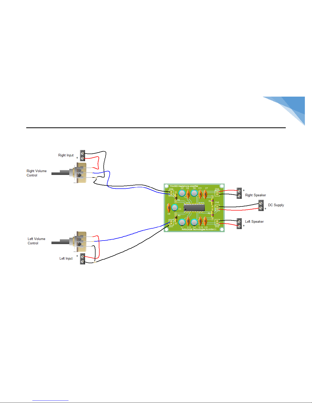
Wiring Diagram
 Loading...