

Page 1

Wiirreelleessss 880022..1111nn 44 PPoorrttss AADDSSLL22//22++ RRoouutteerr
W
User Manual
Wireless 802.11n 4 Ports ADSL2/2+ Router i
Page 2

Copyright
The contents of this publication may not be reproduced in any part or as a whole, stored, transcribed in
an information retrieval system, translated into any language, or transmitted in any form or by any means,
mechanical, magnetic, electronic, optical, photocopying, manual, or otherwise, without the prior written
permission.
Trademarks
All product, company, brand names are trademarks or registered trademarks of their respective
companies. They are used for identification purpose only. Specifications are subject to be changed without
prior notice.
Wireless 802.11n 4 Ports ADSL2/2+ Router ii
Page 3

FCC Radiation Norm
This equipment has been tested and found to comply with limits for a Class B digital device pursuant to 47
CFR, Part 2 and Part 15 of the Federal Communication Commission (FCC) rules. Operation is subject to the
following two conditions:
1. This device may not cause harmful interference
2. This device must accept any interference received including interferences that may cause
undesired operations.
CE Radiation Norm
This equipment has been tested and found to comply with the limits of the European Council Directive
99/5/EC on the approximation of the law of the member states relating to EN 300 328 V1.4.1 (2003-04), EN
301 489-1 V1.4.1 (2002-08) and EN 301 489-17 V1.2.1 (2002-08) and EN 60950.
FCC & CE Compliance Statement
These limits are designed to provide reasonable protection against radio interference in a residential
environment. This equipment can generates, uses and radiate radio frequency energy and, if not installed
and used in accordance with the instructions, may cause harmful interference to radio communications.
However, there is no guarantee that interference will not occur in a particular installation. If this equipment
does cause harmful interference to radio or television reception, which is found by turning the equipment ON
and OFF, the user is encouraged to try to reduce the interference by one or more of the following measures:
Reorient or relocate the receiving antenna
Increase the separation between the equipment and the receiver
Connect the equipment into an outlet on a circuit different from that to which the receiver is connect to
Consult a dealer or an experienced technician for assistance
CAUTION!
The Federal Communication Commission warns the user that changes or modifications to the unit not
expressly approved by the party responsible for compliance could void the user’s authority to operate the
equipment.
FCC RF Radiation Exposure Statement
This equipment must be installed and operated in accordance with provided instructions and the
antenna(s) used for this transmitter must be installed to provide a separation distance of at least 20 cm
from all persons and must not be co-located or operating in conjunction with any other antenn a or
transmitter. End-users and installers must be provide with antenna installation instructions and
transmitter operating conditions for satisfying RF exposure compliance.
Wireless 802.11n 4 Ports ADSL2/2+ Router iii
Page 4

Contents
Copyright........................................................................................................................................... ii
Chapter 1 Introduction .....................................................................................................................1
1.1 Features......................................................................................................................................2
1.2 Scope..........................................................................................................................................4
1.3 Audience....................................................................................................................................5
1.4 Document Structure...................................................................................................................6
1.5 System Requirement..................................................................................................................7
1.6 Packet Contents .........................................................................................................................8
Chapter 2 Knowing The 4 Ports 11g Wireless ADSL2/2+ Router.................................................9
2.1 Front Panel:................................................................................................................................9
2.2 Back Panel:..............................................................................................................................10
2.3 Connection Mechanism:..........................................................................................................11
Chapter 3 Setting up the TCP/IP in Windows ..............................................................................13
3.1 Windows ME / 98....................................................................................................................14
3.2 Windows 2000.........................................................................................................................15
3.3 Windows XP............................................................................................................................16
3.4 Windows Vista.........................................................................................................................17
3.5 Windows 7...............................................................................................................................18
Chapter 4 Device Administration...................................................................................................19
4.1 Login..........................................................................................................................................1
4.2 Setup Wizard..............................................................................................................................3
4.3 LAN...........................................................................................................................................1
4.4 Wireless......................................................................................................................................1
4.4.1 Wireless – Basic Settings ....................................................................................................2
4.4.2 Wireless – Advanced Setting ...............................................................................................4
4.4.3 Wireless – Security..............................................................................................................6
4.4.4 Wireless – Access Control...................................................................................................8
4.4.5 Wireless – WPS .................................................................................................................11
4.4.6 Wireless – MBSSID...........................................................................................................12
4.5 WAN........................................................................................................................................14
4.5.1 WAN – Channel Config.....................................................................................................15
4.5.1.1 WAN – Channel config – Bridge Mode......................................................................17
4.5.1.2 WAN – Channel config – MER(Mac Encapsulation Routing) Mode.........................19
4.5.1.3 WAN – Channel config – PPPoE Mode.....................................................................22
4.5.1.4 WAN – Channel config – PPPoA Mode.....................................................................25
4.5.1.5 WAN – Channel config – 1483 Routed Mode............................................................28
Wireless 802.11n 4 Ports ADSL2/2+ Router iv
Page 5

4.5.2 W AN – A TM Settings.........................................................................................................31
4.5.3 W AN – ADSL Settings.......................................................................................................33
4.6 Service .....................................................................................................................................34
4.6.1 Service – DHCP Settings..................................................................................................35
4.6.2 Service – DNS...................................................................................................................37
4.6.2.1 Service – DNS – DNS Server.....................................................................................38
4.6.2.2 Service – DNS – DDNS Server..................................................................................39
4.6.3 Service – Firewall.............................................................................................................40
4.6.3.1 Service – Firewall – IP/Port Filtering.......................................................................41
4.6.3.2 Service – Firewall – MAC Filtering..........................................................................43
4.6.3.3 Service – Firewall – Port Forwarding.......................................................................45
4.6.3.4 Service – Firewall – URL Blocking ...........................................................................47
4.6.3.5 Service – Firewall – DMZ .........................................................................................50
4.6.4 Service – IGMP Proxy......................................................................................................51
4.6.5 Service – UPnP.................................................................................................................53
4.6.6 Service – RIP ....................................................................................................................54
4.7 Advance ...................................................................................................................................56
4.7.1 Advance – ARP table ........................................................................................................57
4.7.2 Advance – Bridging ..........................................................................................................58
4.7.3 Advance – Routing............................................................................................................59
4.7.4 Advance – SNMP..............................................................................................................61
4.7.5 Advance – Port Mapping..................................................................................................62
4.7.6 Advance – IP QoS.............................................................................................................63
4.7.7 Advance – Remote Access.................................................................................................65
4.7.8 Advance – Others..............................................................................................................66
4.8 Diagnostic................................................................................................................................67
4.8.1 Diagnostic – Ping.............................................................................................................68
4.8.2 Diagnostic – ATM Loopback............................................................................................69
4.8.3 Diagnostic – ADSL...........................................................................................................70
4.8.4 Diagnostic – Diagnostic Test............................................................................................71
4.9 Admin ......................................................................................................................................72
4.9.1 Admin – Commit/Reboot...................................................................................................72
4.9.2 Admin – Backup/Restore...................................................................................................73
4.9.3 Admin – System log...........................................................................................................74
4.9.4 Admin – Password ............................................................................................................75
4.9.5 Admin – Upgrade Firmware.............................................................................................76
4.9.6 Admin – ACL.....................................................................................................................77
4.9.7 Admin – Time Zone...........................................................................................................78
4.9.8 Admin – TR-069................................................................................................................79
4.10 Statistics.................................................................................................................................81
4.10.1 Statistics – Interface........................................................................................................82
4.10.2 Statistics – ADSL.............................................................................................................83
Wireless 802.11n 4 Ports ADSL2/2+ Router v
Page 6

Appendix A: Router T erms.............................................................................................................84
Appendix B: Frequently Asked Questions.....................................................................................86
Appendix C: Troubleshooting Guide.............................................................................................90
Appendix D: UPnP Setting on Windows XP (Optional)...............................................................93
Appendix E: Glossary......................................................................................................................97
Wireless 802.11n 4 Ports ADSL2/2+ Router vi
Page 7

Chapter 1 Introduction
Congratulations on your purchase of this outstanding 4-Ports 11n Wireless ADSL2/2+ Router.
This device is an IEEE 802.11n Wireless and 4 Port Switch built-in ADSL 2/2+ Router that allows
ADSL/ADSL2/ADSL2+ connectivity while providing Wireless LAN capabilities for residential,
industries and SOHO environments. Wireless 11n is the 300Mbps wireless networking standard
that’s almost 5 times faster than the widely deployed Wireless-G or the so-called 11g products
found in homes, businesses, and public wireless hotspots around the world.
ADSL2/2+ is a transmission technology used to carry user data over a single twisted-pair line
between the Central Office and the Customer Premises. The downstream data rates can go up to
24 Mbps and the upstream data rates can go up to 1Mbps with length reach up to 22Kft for
ADSL2/2+ connection and 300Mbps transfer data rate for the 11n connection. This device allows
ADSL2/2+ connectivity while providing Wireless LAN capabilities for home or office users. This
asymmetric nature lends itself to applications such as Internet access and video delivery.
minimum setup, you can install and use the router within minutes.
With
4 Ports 11n Wireless ADSL2/2+ Router 1
Page 8

1.1 Features
ADSL Standards Compliance
Full rate ANSI T1.413 Issue2, ITU-T G.992.1 and ITU-T G.992.2 standards compliant.
ITU G.992.3, ITU G.992.5 ADSL2/2+ standards compliant.
Support Annex M and Annex L specification.
Down stream and Upstream data rates up to 24Mbps and 1Mbps.
ATM and PPP Protocols
Support ATM AAL0, AAL2 & AAL5.
Support ITU-T I.610 OAM F4/F5.
Support up to 8 PVCs.
Multiple Protocols over AAL5 (RFC 2684 / RFC 1483).
Support Bridged and Routed Ethernet Encapsulation.
Support VC and LLC based Multiplexing.
Support PPPoA (RFC 2364) standard.
Support PPPoE (RF C 2516) standard.
Traffic classe s: UBR, CBR and VBR-rt, VBR-nrt.
Network Protocols & Features
IP Routing – RIPv1 and RIPv2.
Support Static Routing.
DHCP Server, Relay and Client.
Support DNS Relay.
Support DDNS features.
Support SNM P functionality.
Support IP QoS features.
Support IGMP functionalit y
Support IP Filter and MAC Filter functionality.
URL Blocking feature supported.
Support Port Forwarding features.
Support DMZ functionality.
Support NAT and NAPT (P AT) functionality with extensive ALG supported.
Support VPN Pass-T hrough.
Built-in Firewall features.
4 Ports 11n Wireless ADSL2/2+ Router 2
Page 9

Bridging
Support IEEE 802.1d Transparent Bridging.
Support IGMP Snooping.
Support MAC Learni ng Address features.
IEEE 802.11n Wireless Standards
IEEE 802.11n/g/b standards compliant.
Support data rates up to 300Mbps (Auto-Rate Capable).
Support OFDM (64QAM, 16QAM, QPSK, BPSK) and DSSS (DBPSK, DQPSK, CCK)
modulation.
Support WEP/WPA/WPA2/802.1X Encryption for dat a security.
Support Wirel ess Access Control functionality.
Support Hidden SSID.
Support WDS features.
Support WPS features.
Support 2.412GHZ ~ 2.484GHz frequency ranges.
Management
Web-based Configuration / Management.
Support FTP/TFTP/Telnet Management / Configuration.
Support Rem ote Access Management / Configuration.
Firmware upgrade and Reset to default via Web management.
Restore factory default setting via Web or hardware reset button.
WAN and LAN connection statistics.
Support Password Authentication.
Device System Log.
Built-in Diagnostic Test.
UPnP
Support UPnP functionality.
Ethernet Standards
Built-in 4 Ports 10/100Mbps Ethernet Switch which compliant with IEEE 802.3x standards
Automatic MDI/MDI-X crossover for 100BASE-TX and 10BASE-T ports.
Auto-negotiation and speed-auto-sensing support.
Port based VLAN supported in any combination.
4 Ports 11n Wireless ADSL2/2+ Router 3
Page 10

1.2 Scope
This document provides the descriptions and usages for the 4 Ports 11n Wireless ADSL2/2+
Router’s Web pages that are used in the configuration and setting process. Both basic and advanced
descriptions and concepts are discussed. To help the reader understand more about these Web pages,
some questions and answers (Q&A) are appended after the definition of each Web page along with the
appendices at the end of the guide.
4 Ports 11n Wireless ADSL2/2+ Router 4
Page 11

1.3 Audience
This document is prepared for use by those customers who purchase the 4 Ports 11n Wireless
ADSL2/2+ Router and using the provided or embedded firmware. It assumes the reader has a basic
knowledge of ADSL/ADSL2/ADSL2+ Wireless and networking.
4 Ports 11n Wireless ADSL2/2+ Router 5
Page 12

1.4 Document Structure
Chapter 1: Introduction, provides a brief introduction to the product and user guide.
Chapter 2: Knowing The 4 Ports 11n Wireless ADSL2/2+ Router, provides device specifications
and hardware connection mechanism.
Chapter 3: Setting Up TCP/IP in Windows, provides Windows system Network’s configurations.
Chapter 4: Device Administration, describes the pages found under the Ad min menu. These p ages
allow the user to view, change, edit, upd ate, and save the 4 Ports 11n Wireless
ADSL2/2+ Router’s configurations or settings.
Appendix A: Router Terms, provides an introduction to basic Router Terms.
Appendix B: Frequently Asked Que stion s, is a compilation of useful questions regarding the 4 Ports
1 1n Wirel ess ADSL2/2+ Router.
Appendix C: Troubleshooting Guide, is a compilation of questions and answers relating to
common problems dealing with Windows networking and the 4 Port s 11n Wireless
ADSL2/2+ Router Configurations.
Appendix D: UPnP Setting, provides UPnP configurations procedures under Windows XP.
Appendix E: Glossary, provides definitions of terms and acronyms of this 4 Ports 11n Wireless
ADSL2/2+ Router.
4 Ports 11n Wireless ADSL2/2+ Router 6
Page 13

1.5 System Requirement
Check and confirm that your system confirm the following minimum requirements:
Personal computer ( PC/Notebook ).
Pentium III compatible processor and above.
Ethernet LAN card or IEEE 802.11n/g/b Wireless adaptor installed with TCP/IP protocol.
64 MB RAM or more.
50 MB of free disk space ( Minimum ).
Internet Browser.
CD-ROM Drive.
4 Ports 11n Wireless ADSL2/2+ Router 7
Page 14

1.6 Packet Contents
The 4 Ports 1 1n Wireless ADSL2/2+ Router package contains the following items:
One 4 Ports 11n Wireless ADSL2/2+ Router
One Power Adapter
One RJ-11 ADSL Cable
One CAT-5 Ethernet Cable
One CD-ROM ( Driver / Manual / Quick Setup Guide )
If any of the above items are damaged or missing, please contact your dealer immediately.
4 Ports 11n Wireless ADSL2/2+ Router 8
Page 15

Chapter 2 Knowing The 4 Ports 11n Wireless ADSL2/2+ Router
2.1 Front Panel
The 4 Ports 11n Wireless ADSL2/2+ Router’s LEDs indicators display information about the
device’s status.
PWR Lights up when 4 Ports 11n Wireless ADSL2/2 + Router is powered on.
1
2
3
4
WLAN
ADSL
INTERNET Lights up when connection is establi sh ed to Internet.
WPS Blinking when WPS is in progress.
Blinking when Port 1 of this 4 Ports 11n Wireless ADSL2/2+ Router is sending or receiving
data.
Blinking when Port 2 of this 4 Ports 11n Wireless ADSL2/2+ Router is sending or receiving
data.
Blinking when Port 3 of this 4 Ports 11n Wireless ADSL2/2+ Router is sending or receiving
data.
Blinking when Port 4 of this 4 Ports 11n Wireless ADSL2/2+ Router is sending or receiving
data.
Lights up when Wireless system is ready.
Blinking when router is sending or receiving data via wireless
Lights up when a successful ADSL2/2+ connection is established.
Blinking when it is attempting to make an ADSL connection with ISP.
4 Ports 11n Wireless ADSL2/2+ Router 9
Page 16

2.2 Back Panel
!
The back panel of the 4 Ports 11n Wireless ADSL2/2+ Router contains ADSL, Ethernet Switches,
Reset, Power Adapter connection and 2.4GHz Dipole Antenna connector.
ADSL Port for connecting to the ADSL2/2+ Service Provider.
WPS Wi-Fi Protected Setup button
Ports 1~4 Four 10/100Mbps Ethernet Ports for connecting to the network devices
USB(option) USB host for connecting portable HDD
Power Power adapter connector.
ON/OFF Power ON/OFF Switch
Antenna 2.4GHz Dipole Antenna.
RESET Button:
Reboot & Restore the 4 Ports 11g Wireless ADSL2/2+ Router to factory
defaults.
To “Reset” the 4 Ports 11n Wireless ADSL2/2+ Router to factory defaults:
Ensure that the device is powered on.
Press the Reset button for more than 5 seconds and release. Wait for 30 seconds after releas e the
Reset button. Do not power off the device during the reset process.
The default settings are now restored after 30 seconds.
To “Reboot” the 4 Ports 11n Wireless ADSL2/2+ Router:
Ensure that the device is powered on.
Press the Reset button for 2~5 seconds and release. Wait for 30 seconds after release the Reset
button.
To setup WPS via WPS button:
Press the WPS button for 2 seconds and release. The Wireless LED will be blinking to establish
WPS connection.
4 Ports 11n Wireless ADSL2/2+ Router 10
Page 17

2.3 Connection Mechanism
This section describes the hardware connection mechanism of 4 Ports 11n Wireless ADSL2/2+ Router
on your Local Area Network (LAN) connected to the Internet, how to configure your 4 Ports 11n Wireless
ADSL2/2+ Router for Internet access or how to manually configure your Internet connection.
You need to prepare the following items before you can establish an Internet connection through your 4
Ports 11n Wireless ADSL2/2+ Router:
1. A computer/notebook which must have an installed Ethernet Adaptor and an Ethernet Cable, or
2. A computer/notebook which have Wireless-b or Wireless-g wireless adaptor properly installed.
3. ADSL/ADSL2/ADSL2+ service account and configuration information provided by your Internet
Service Provider (ISP). You will need one or more of the following configuration parameters to
connect your 4 Ports 11n Wireless ADSL2/2+ Router to the Internet:
a. VPI/VCI parameters
b. Multiplexing Method or Protocol Type or Encapsulation Type
c. Host and Domain Names
d. ISP Login Name and Password
e. ISP Domain Name Server (DNS) Address
f. Fixed or Static IP Address.
Figure below shows the overall hardware connection mechanism o f your 4 Ports 11n Wireless ADSL2/2+
Router.
4 Ports 11n Wireless ADSL2/2+ Router 11
Page 18
Following are the steps to properly connect your 4 Ports 11n Wireless ADSL2/2+ Router:
!
!
1. Turn off your computer/notebook.
2. Connect the ADSL port of your 4 Ports 11n Wireless ADSL2/2+ Router to the wall jack of the
ADSL/ADSL2/ADSL2+ Line with a RJ-11 cable.
3. Connect the Ethernet cable (RJ-45) from your 4 Ports 11n Wireless ADSL2/2+ Router (Switch ) to
the Ethernet Adaptor in your computer.
4. Connect the Power adaptor to the 4 Ports 11n Wireless ADSL2/2+ Router and plug it into a Power
outlet.
The Power light will lit after turning on the 4 Ports 1 1g Wireless ADSL2/2+
Router.
Use the Power Adaptor exclusively in combinatio n with the equipment
5. Turn on your computer.
6. Refer to the next section to setup or configure your system’s Network Adaptor.
supplied and do not use any other kind of power adaptor for the
equipment.
4 Ports 11n Wireless ADSL2/2+ Router 12
Page 19

Chapter 3 Setting up the TCP/IP in Windows
y
k
The instruction in this chapter will help you configure your computers to be able to communicate with this
4 Ports 11n Wireless ADSL2/2+ Router.
Computers access the Internet using a protocol called TCP/IP (Transmission Control Protocol/ Internet
Protocol). Each computer/notebook on your network must have TCP/IP installed and selected as its
networking protocol. If a Network Interface Card (NIC) is already installed in your PC, then TCP/IP is probabl y
already installed as well.
The following description assumes 4 Ports 11n Wireless ADSL2/2+ Router been set to factory default. (If
not, please hold the reset button down for 5~10 seconds). The default of the 4 Ports 11n Wireless ADSL2/2+
Router’s LAN IP is 192.168.1.1.
Follow the procedures below to set your computer/notebook function as a DHCP Client.
!
Restart and Reboot your Windows system might be necessary after setting your
computer function as a DHCP Client. In order to properl
“OK” to restart your Windows system.
activate your choice, clic
4 Ports 11n Wireless ADSL2/2+ Router 13
Page 20
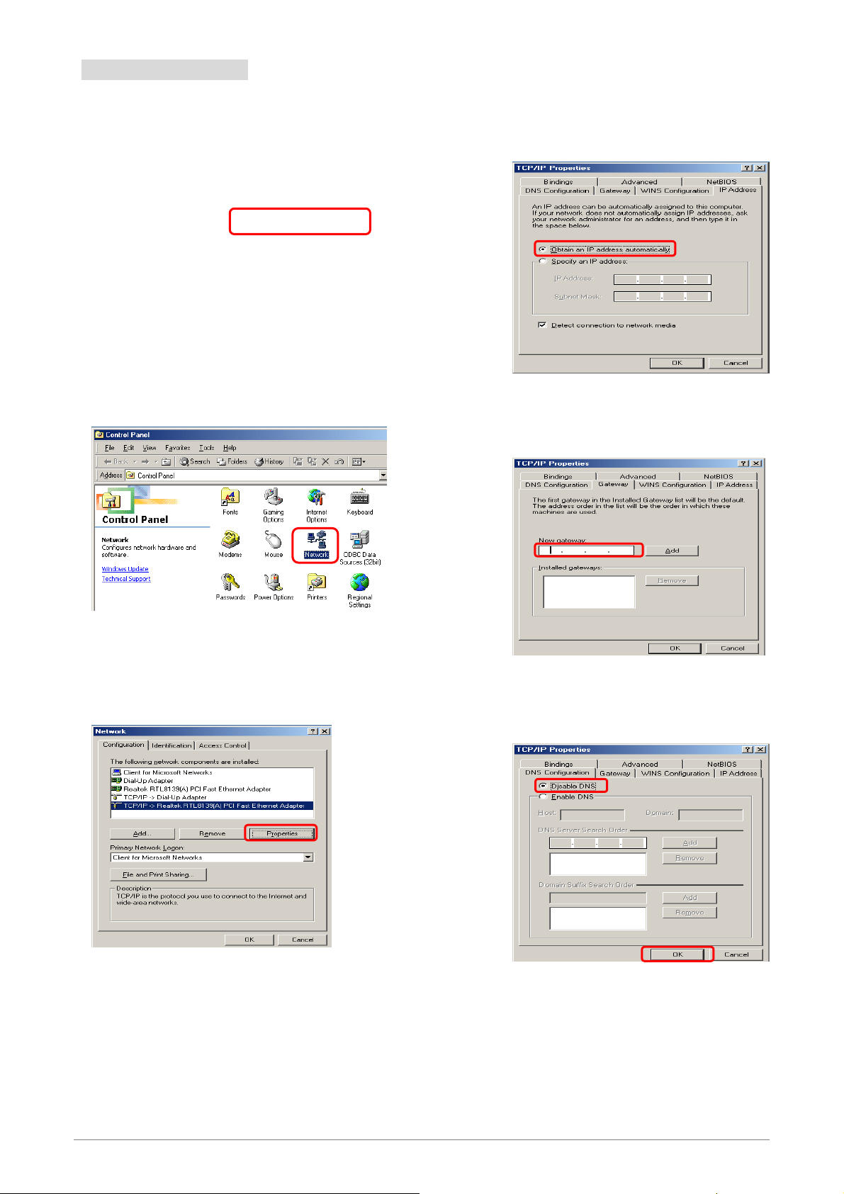
3.1 Windows ME / 98
Step 1: Click Start→Settings→Control Panel.
Step 2: Double-click the Network icon.
Step 4: Go to IP Address icon and select
Obtain an IP address.
Step 5: Go to Gateway icon and erase all
previous setting.
Step 3: Go to Configuration icon, select network
adapter installed and click Properties.
1
2
Step 6: Go to DNS Configuration icon, select
Disable DNS and click OK.
4 Ports 11n Wireless ADSL2/2+ Router 14
2
Page 21
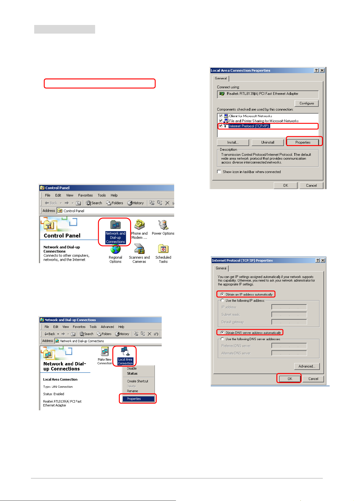
3.2 Windows 2000
k
Step 1: Click Start→Settings→Control Panel.
Step 4: Select Internet Protocol (TCP/IP) and clic
Properties.
1
Step 2: Double-click the Network and Dial-up
Connections.
Step 3: Right Click the Local Area Connection and
select Properties.
2
Step 5: Select Obtain an IP address automatically
and DNS server address automatically.
Then, click OK.
1
2
1
3
2
4 Ports 11n Wireless ADSL2/2+ Router 15
Page 22

3.3 Windows XP
Step 1: Click Start→Control Panel→Classic View.
Step 2: Double-click the Network Connections.
Step 4: Go to General icon, select Internet Protocol
(TCP/IP) and click Properties.
1
2
Step 3: Right Click on the Local Area Connection and
select Properties.
1
Step 5: Go to General icon, select Obtain an IP
address automatically and DNS server
address automatically.
Then, click OK.
1
2
3
4 Ports 11n Wireless ADSL2/2+ Router 16
2
Page 23

3.4 Windows Vista
Step 1: Click Start→Control Panel.
Step 4: Right Click on the Local Area Connection
and select Properties.
Step 2: Double-click the Network and Sharing Center.
1
2
Step 5: Go to General icon, select Internet Protocol
Version 4 (TCP/Ipv4) and click Properties.
1
Step 3: Click on the Manage network connections.
2
Step 6: Go to General icon, select Obtain an IP
address automatically and DNS server
address automatically.
Then, click OK.
1
2
1
2
3
4 Ports 11n Wireless ADSL2/2+ Router 17
Page 24

3.5 Windows 7
Step 1: Click Start→Control Panel.
Step 2: Click the View network status and tasks.
Step 4: Right click on the Local Area Connection
and select Properties.
1
2
Step 5: Select Internet Protocol Version 4
(TCP/IPv4) and click Properties.
Step 3: Click on the Change adapter settings.
1
2
Step 6: Go to General icon, select Obtain an IP
address automatically and DNS server
address automatically.
1
2
3
4 Ports 11n Wireless ADSL2/2+ Router 18
Page 25

Chapter 4 Device Administration
For your convenience, an Administrative Utility has been programmed into 4 Ports 11n Wireless
ADSL2/2+ Router. This chapter will explain all the functions in this utility. All the 4 Ports 11n Wireless
ADSL2/2+ Router based administrative tasks are performed through this web utility.
4 Ports 11n Wireless ADSL2/2+ Router 19
Page 26
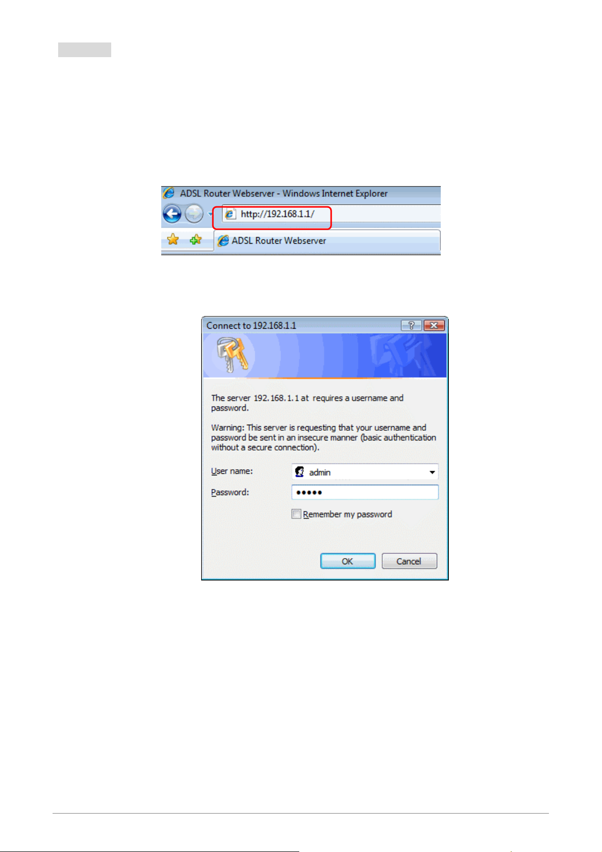
4.1 Login
To access the 4 Ports 11n Wireless ADSL2/2+ Router Configuration screens, follow the following steps
will enable you to log into the 4 Ports 11n Wireless ADSL2/2+ Router:
1.
Launch your web browser, and enter the 4 Ports 11n Wireless ADSL2/2+ Router’s IP Add ress:
“192.168.1.1”
in the
address field then press the “Enter” key to login.
2. Enter your password in the Passwo rd text box . For an admin user, the default password is “admin”.
4 Ports 11n Wireless ADSL2/2+ Router 1
Page 27
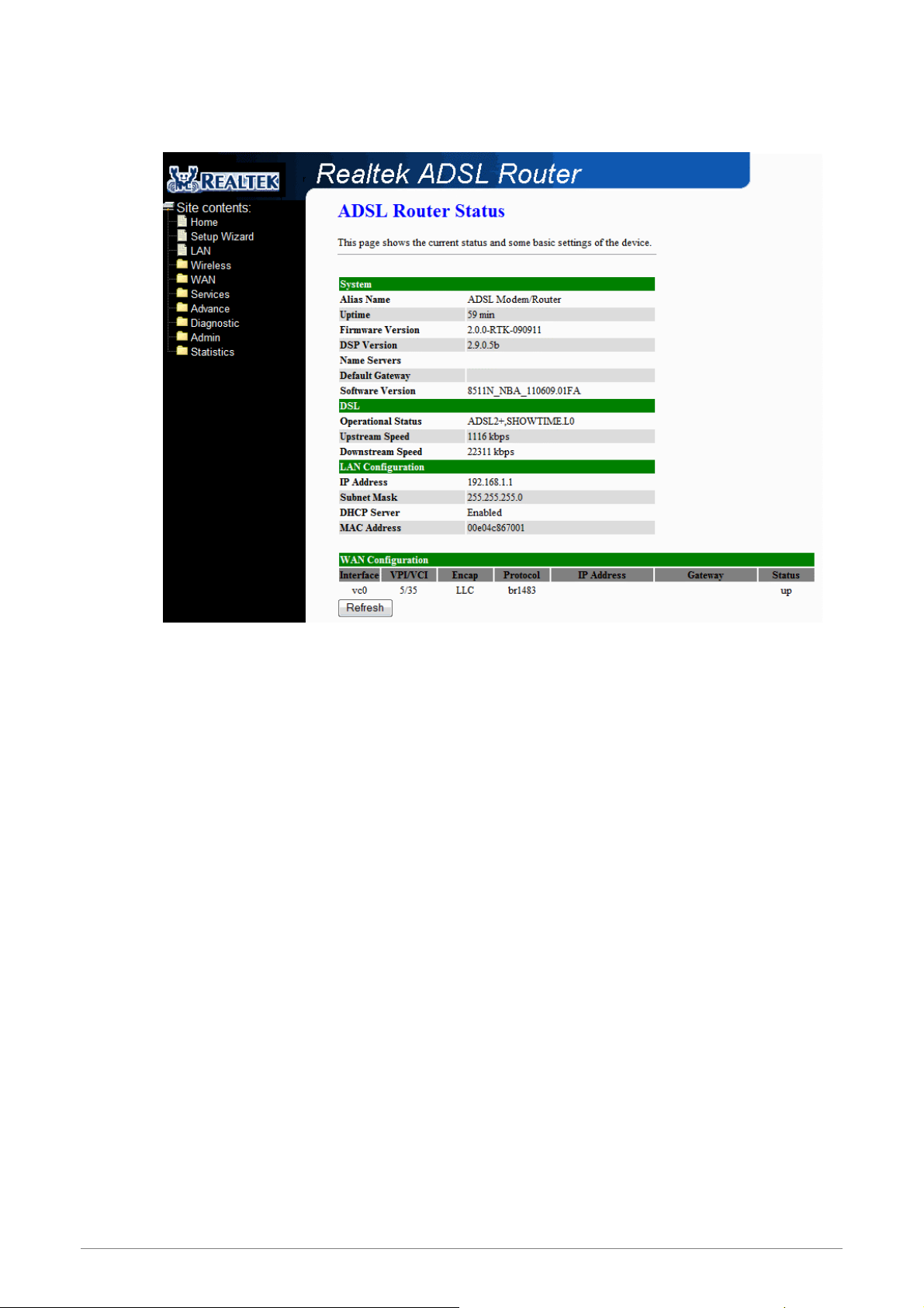
3. Upon entering the address into the web browser, the system HOME page with all the device
information will pop up as shown in following Figure:
This page displays the ADSL modem/router’s current status and settings. This information is read-only
except for the PPPoE/PPPoA channel for which user can connect/disconnect the channel on demand.
Click the “Refresh” button to update the status
Function buttons in this page:
Connect / Disonnect
The two buttons take effect only when PVC is configured as PPPoE/PPPoA mode. Click
Connect/Disconnect button to connect/disconnect the PPP dial up link.
4 Ports 11n Wireless ADSL2/2+ Router 2
Page 28
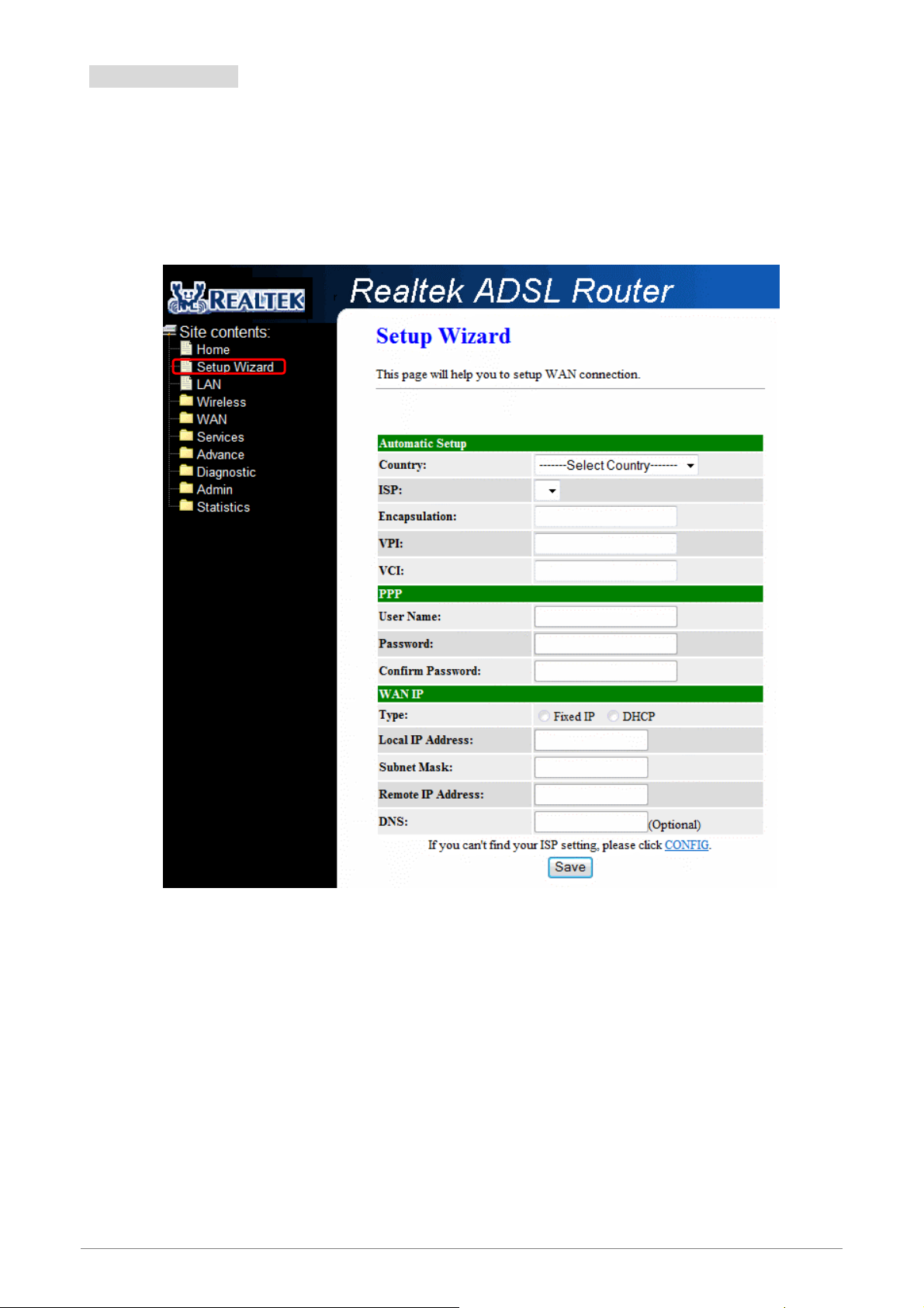
4.2 Setup Wizard
The Setup Wizard is a presetting wizard which meant to help you install the 4 Ports 11n Wireless
ADSL2/2+ Router quickly and easily.
Click on “Setup Wizard” and the following screen will pop-u p:
Follow the “Steps” describe below to complete your installation.
4 Ports 11n Wireless ADSL2/2+ Router 3
Page 29
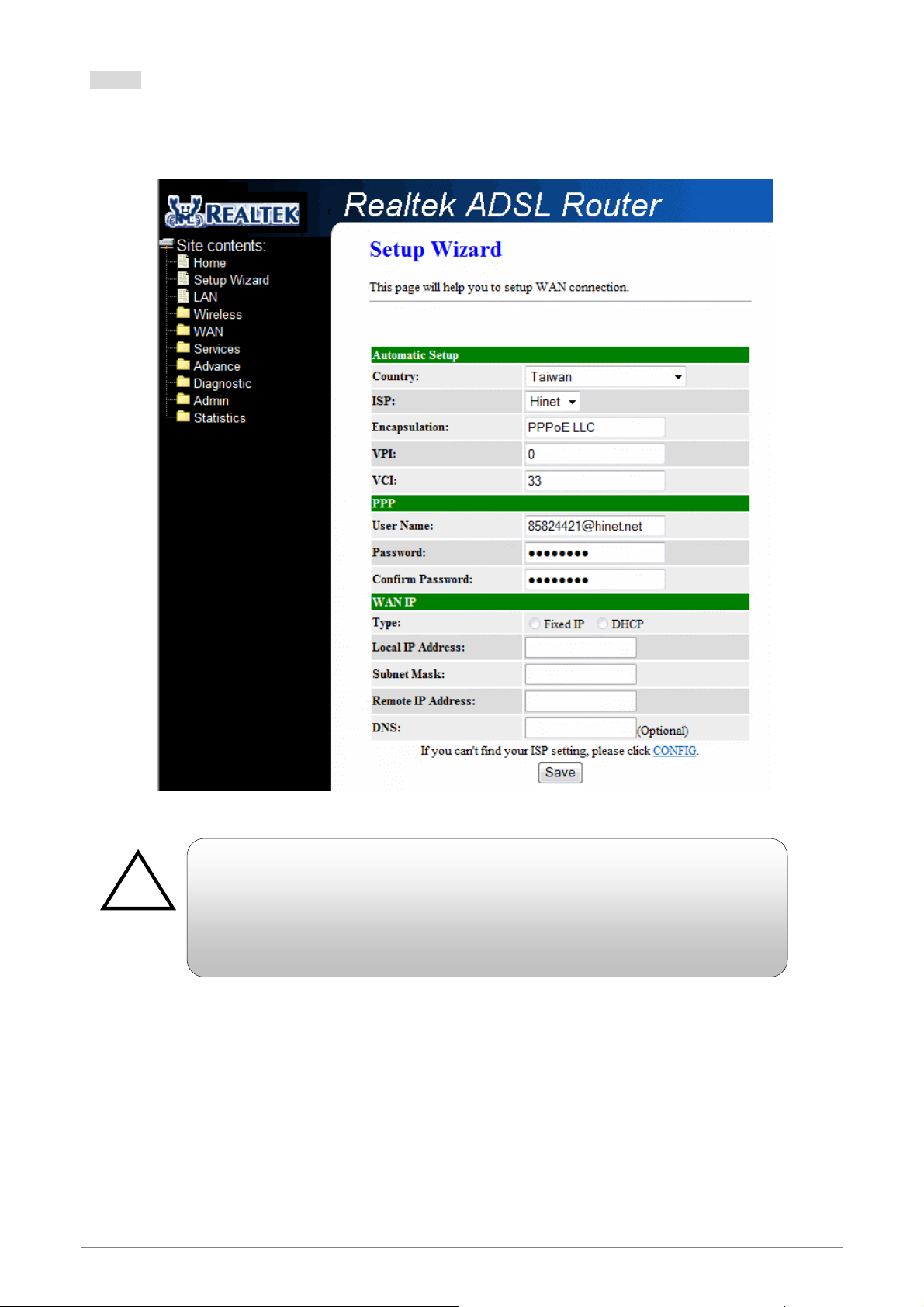
Step 1: Select your country from the Country list and the ADSL service provider from the ISP List (If there
!
are more than two ISP in your country) and note the “Encapsulation” type and “VPI & VCI”
setting.
Click “CONFIG” if you can’t find any available parameters from the
presetting country list.
Check your ISP immediately for the setting/c onfiguration details.
4 Ports 11n Wireless ADSL2/2+ Router 4
Page 30
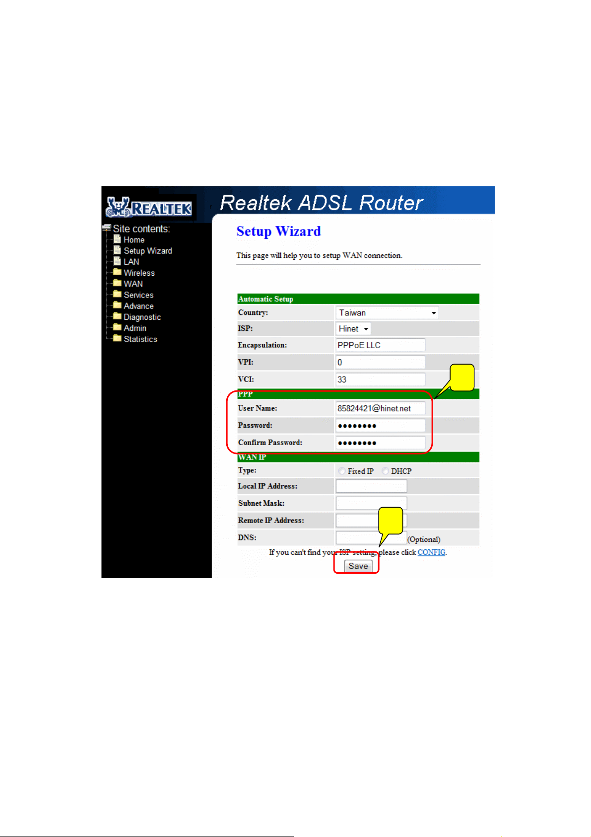
A. For countries with the following “Encapsulation” type , you will enter into set Username and
Password window as shown below:
PPPoA VC-Mux
PPPoA LLC
PPPoE VC-Mux
PPPoE LLC
1
2
Manually enter your “User Name” and “Password” which will be provided by your Service Provider
(ISP). Click “Save” after setup.
Click Commit and Reboot button to commit changes to system memory and reboot router.
4 Ports 11n Wireless ADSL2/2+ Router 5
Page 31

4 Ports 11n Wireless ADSL2/2+ Router 6
Page 32

B. For countries with the following “Encapsulation” , the following window will pop-up:
!
1483 Routed IP VC-Mux
1483 Routed IP LLC
1483 Bridged IP VC-Mux
1483 Bridged IP LLC
In this current window, you will find TWO different Connection Ty pe:
Fixed IP (Fixed IP by ISP)
DHCP (Get IP dynamically from ISP)
Click “CONFIG” if you can’t find any available parameters from the
presetting country list.
Check your ISP immediately for the setting/c onfiguration details.
4 Ports 11n Wireless ADSL2/2+ Router 7
Page 33

Fixed IP: Click the radio button to enable Fixed IP option .
1
2
Manually enter the “Local IP Address”, “Subnet Mask”, “Remote IP Address”(Default
Gateway) and “DNS” which will be provided by your ISP. Click “Save” after your setting.
Fixed IP Setup: Fixed IP Settings are for users who have a Static IP Address (WAN side)
from their ISP.
Local IP Address: This is the Static IP Address given by your ISP.
Subnet Mask: This is the Subnet Mask provided by your ISP.
Remote IP Address: This is your gateway IP address.
DNS: This is the DNS address specify by your ISP.
4 Ports 11n Wireless ADSL2/2+ Router 8
Page 34

DHCP (Get IP dynamically from ISP): Click the radio button to enable DHCP (Get IP dynamically
from ISP) option.
1
Nothing to be filled under this mode. Just click the “Save” button to confirm your setting.
Click Commit and Reboot button to commit changes to system memory and reboot router.
4 Ports 11n Wireless ADSL2/2+ Router 9
Page 35

Step 2: The following page with the device setup information will be displayed.
NOTE: If the final settings are different from what you’d selected in STEP 1, click Setup Wizard and redo the
setup procedures or else check your dealer immediately for technical support.
4 Ports 11n Wireless ADSL2/2+ Router 1
Page 36

Step 3:
Step 4: The following Google website index page will display on your screen. This shows your ADSL
Launch your web browser, and enter the Google Website Address:
the
address field then press “Enter”.
connection is correctly set and access to the Internet is now available.
“www.google.com”
in
4 Ports 11n Wireless ADSL2/2+ Router 1
Page 37

4.3 LAN
This page shows the current setting of LAN interface. You can set IP Address, Subnet Mask, IGMP
Snooping and Ethernet to Wireless Blocking for LAN interface in this page.
Fields in this page:
Field Description
IP Address The IP address your LAN hosts use to identify the device’s LAN port.
Subnet Mask
IGMP Snooping Enable/Disable the IGMP snooping function for the multiple bridged LAN po rts.
Ethernet to Wireless
Blocking
Function buttons in this page:
Apply Changes
Click to save the setting to the configuration. New parameters will take effect after save into flash
memory and reboot the system. See section “Admin” for save details.
LAN subnet mask.
Enable/Disable the Ethernet to Wireless Blocking function
4 Ports 11n Wireless ADSL2/2+ Router 1
Page 38

4.4 Wireless
You can view Wireless link in the left navigation bar. Following are the options available under Wireless:
Basic Settings
Advanced Settings
Security
Access Control
WDS
WPS
MBSSID
4 Ports 11n Wireless ADSL2/2+ Router 1
Page 39

4.4.1 Wireless – Basic Settings
To configure the wireless basic settings, click on the Basic Settings link (Wireless > Basic Settings) in
the left navigation bar. A screen is displayed as shown in following figure.
Fields in this page:
Field Description
Disable Wireless LAN
Interface
Band Select the appropriate band from the list provided to correspond with your network
Mode The selections are: AP, AP+WDS.
SSID The Service Set Identifier (SSID) or network name. It is case sensitive and must not
Channel Width The selections are 40MHz or 20MHz.
Control Sideband
Check it to disable the wireless function for ADSL router.
setting.
exceed 32 characters, which may be any keyboard character. The mobile wireless
stations shall select the same SSID to be able to communicate with your ADSL
router.
Specify if the extension channel should be in the Upper or Lower sideband.
Control and the secondary extension channels are only applicable if your ADSL
router is operating at 40 MHz bandwidth and the band is config ured as
2.4GHz(B+G+N), 2.4GHz(G+N) or 2.4GHz(N).
Channel Number Select the appropriate channel from the list provided to correspond with your
network settings. You shall assign a different channel for each AP to avoid signal
interference.
Radio Power (mW) The AP Radi o Power. Select 60mW, 30mW or 15mW power level from the drop
down manual. The default Radio Power level is 60mW. It’s recommended to leave
this setting as its default.
4 Ports 11n Wireless ADSL2/2+ Router 2
Page 40

Function buttons in this page:
Associated Clients
Click Show Active Clients button and it will show the clients currently associated with the ADSL router.
Apply Changes
Change the settings. New parameters will take effect after save into flash memory and reboot the
system. See section “Admin” for save details.
4 Ports 11n Wireless ADSL2/2+ Router 3
Page 41

4.4.2 Wireless – Advanced Setting
This page allows advanced users who have sufficient knowledge of wireless LAN. These setting shall
not be changed unless you know exactly what will happen for the changes you made on your DSL router.
Fields in this page:
Field Description
Authentication Type
Fragment Threshold This value should remain at its default setting of 2346. It specifies the maximum size
Open System: Open System authentication is not required to be successful while a
client may decline to authenticate with any particular other client.
Shared Key: Shared Key is only available if the WEP option is implemented. Shared
Key authentication supports authentication of clients as either a member of those
who know a shared secret key or a member of those who do not. IEEE 802.11
Shared Key authentication accomplishes this without the need to transmit the secret
key in clear. Requiring the use of the WEP privacy mechanism.
Auto: Auto is the default authentication algorithm. It will change its authentication
type automatically to fulfill client’s requirement.
for a packet before data is fragmented into multiple p acket s. If you experie nce a high
packet error rate, you may slightly increases the “Fragment Threshold” value within
the value range of 256 to 2346. Setting this value too low may result in poor network
performance. Only minor modifications of this value are recommended.
RTS Threshold This value should remain at its default setting of 2347. Should you encounter
inconsistent data flow, only minor modifications are recommended. If a network
packet is smaller than the preset “RTS threshold” size, the R T S/CTS mechanism will
not be enabled. The ADSL modem (or AP) sends Request to Send (RTS) frames to
4 Ports 11n Wireless ADSL2/2+ Router 4
Page 42

a particular receiving station and negotiates the sending of a data frame. After
receiving an RTS, the wireless station responds with a Clear to Se nd (CTS) fra me to
acknowledge the right to begin transmission.
Beacon Interval The Beacon Interval value indicates the frequency interval of the beacon. Enter a
value between 20 and 1024. A beacon is a packet broadcast by the ADSL modem
(or AP) to synchronize the wireless network. The default is 100.
Data Rate The rate of data transmission should be set depending on the speed of your wireless
network. You should select from a range of transmission speeds, or you can select
Auto to have the ADSL modem (or AP) automatically use the fastest possible data
rate and enable the Auto-Fallba ck feature. Auto-Fallback will negotiate the best
possible connection speed between the AP and a wireless client. The default setting
is Auto.
Preamble Type The Preamble T y pe defines the length of the CRC (Cyclic Redund ancy Check) block
for communication between the AP and mobile wireless stations. The preamble
consists of the Synchronization and Start Frame Delimiter (SFD) fields. The sync
field is used to indicate the delivery of a frame to wireless stations, to measure
frequency of the radio signal, to perform corrections if needed. The SFD at the end
of the Preamble is used to mark the start of the frame. If you are not using any
802.11b devices in your network, you can configure the Preamble type to Short for
optimum performance. The Long Preamble type should be used when both 802.11g
and 802.11b devices exist on your network. Note that high network traffic areas
should use the short preamble type. CRC is a common technique for detecting data
transmission errors.
Broadcast SSID If this option is enabled, the device will automatically transmit their network name
(SSID) into open air at regular interval. This feature is intended to allow clients to
dynamically discover and roam between WLANs; if this option is disabled, the device
will hide its SSID. When this is done, the station cannot directly discover its WLAN
and MUST be configure with the SSID. Note that in a home Wi-Fi network, roaming
is largely unnecessary and the SSID broadcast feature serves no useful purpose.
You should disable this feature to improve the security of your WLAN.
Relay Blocking
Protection Prevent from interference of 11b device. Do not disable protection if there is a
When Relay Blocking is enabled, wireless clients will not be able to directly access
other wireless clients.
possibility that 802.11b or 802.1 1g devices will use your wireless network. Disabled
protection to maximize 802.11n throughput under most conditions.
Aggregation Aggregating data unit.
Short GI Short guard interval.
Function buttons in this page:
Apply Changes
Change the settings. New parameters will take effect after save into flash memory and reboot the
system. See section “Admin” for save details.
4 Ports 11n Wireless ADSL2/2+ Router 5
Page 43

4.4.3 Wireless – Security
This screen allows you to setup the wireless security. Turn on WEP or WPA by using encryption keys
could prevent any unauthorized access to your WLAN.
Fields in this page:
Field Description
SSID Type There are Root,VAP0, VAP1, VAP2, VAP3.
Encryption There are 4 types of security to be selected. To secure your WLAN, it’s strongly
recommended to enable this feature.
WEP: Make sure that all wireless devices on your network are using the same
encryption level and key. Click Set WEP Key button to set the encryption key.
WPA (TKIP): WPA uses Temporal Key Integrity Protocol (TKIP) for data encryption.
TKIP utilized a stronger encryption method and incorporates Message Integrity Code
(MIC) to provide protection against hackers.
WPA2 (AES): WPA2, also known as 802.11i, uses Advanced Encryption Standard
(AES) for data encryption. AES utilized a symmetric 128-bit block data encryption.
WAP2 Mixed: The AP supports WPA (TKIP) and WPA2 (AES) for data encryption.
The actual selection of the encryption methods will depend on the clients.
Use 802.1x
Authentication
Check it to enable 802.1x authentication. This option is select able only when the
“Encryption” is choose to either None or WEP. If the “Encryption” is WEP, you need
to further select the WEP key length to be either WEP 64bits or WEP 128bits.
WP A Authentication
Mode
There are 2 types of authentication mode for WPA.
Enterprise (RADIUS): Enterprise RADIUS uses an external RA DIUS server to
perform user authentication. To use WPA RADIUS, enter the IP address of the
RADIUS server , the RADIUS port (default is 1812) and the shared secret from the
RADIUS server . Please refer to “Authentication RADIUS Server” setting below for
4 Ports 11n Wireless ADSL2/2+ Router 6
Page 44

RADIUS setting. The WPA algorithm is selected between TKIP and AES, please
A
refer to “WPA cipher Suite” below.
Pre-Shared Key: Pre-Shared Key authentication is based on a shared secret thatis
known only by the parties involved. To use WPA Pre-Shared Key, select key format
and enter a password in the “Pre-Shared Key Format” and “Pre-Shared Key” setting
respectively. Please refer to “Pre-Shared Key Format” and “Pre-Shared Key” setting
below.
Pre-Shared Key
Format
PassPhrase: Select this to enter the Pre-Shared Key secret as user-friendly textual
secret.
Hex (64 characters): Select this to enter the Pre-Shared Key secret as hexadecimal
secret.
Pre-Shared Key Specify the shared secret used by this Pre-Shared Key. If the “Pre-Shared Key
Format” is specified as PassPhrase, then it indicates a passphrase of 8 to 63 bytes
long; or if the “Pre-Shared Key Format” is specified as Hex, then it indicates a
64-hexadecimal number.
uthentication RADIUS
Server
If the WPA-RADIUS is selected at “WPA Authentication Mode”, the port (default is
1812), IP address and password of external RADIUS server are sp ecified here.
Function buttons in this page:
Apply Changes
Change the settings. New parameters will take effect after save into flash memory and reboot the
system. See section “Admin” for save details.
4 Ports 11n Wireless ADSL2/2+ Router 7
Page 45

4.4.4 Wireless – Access Control
This page allows administrator to have access control by enter MAC address of client stations. When
Enable this function, MAC address can be added into access control list and only those clients whose
wireless MAC address are in the access control list will be able to connect to your DSL router.
Fields in this page:
Field Description
Wireless Access
Control Mode
MAC Address Enter client MAC address and press “Apply Changes” button to add client MAC
The Selections are:
Disable
Disable the wireless ACL feature.
Allow Listed
When this option is selected, no wireless clients except those whose MAC
addresses are in the current access control list will be able to connect (to this
device).
Deny Listed
When this option is selected, all wireless clients except those whose MAC
addresses are in the current access control list will be able to connect (to this
device).
address into current access control list.
Function buttons for the setting block:
Apply Changes
Click to add this entry into the Current Access Control List.
4 Ports 11n Wireless ADSL2/2+ Router 8
Page 46

The Current Access Co ntrol Lis t lists the cl ient MA C a dd resse s. Any wireless client with its MAC address listed
in this access control list will be able to connect to the device. You can select the entries at the Select column
and apply to the following function buttons.
Function buttons for the Current Access Control List:
Delete Selected
Delete the selected entries from the list.
Delete All
Flush the list.
4 Ports 11n Wireless ADSL2/2+ Router 9
Page 47

4.4.5 Wireless – WDS
Wireless Distribution System (WDS) is a system that interconnects BSS to build a premise wide network.
The DSL device supports the WDS protocol, which allows a point to point link to be established between two
APs. Only if you select AP +WDS mode on the Basic Settings page, this WDS page can be configured.
Fields in this page:
Field Description
Enable WDS Check to enable the WDS function.
Add WDS AP This is where you enter the MAC address of the peer AP’ s wireless interface that you
are connecting to.
Function buttons for the setting block:
Apply Changes
Click to add this entry into the Current WDS AP List.
The C u rr en t W DS A P Li st list s the peer MAC addresses of the WDS link. Any AP with it s MAC address list ed in
this WDS AP list may have a WDS link to the device. You can select the entries at the Select column and
apply to the following function buttons.
Function buttons for the Current WDS AP List:
Delete Selected
Delete the selected entries from the list.
Delete All
Flush the list.
4 Ports 11n Wireless ADSL2/2+ Router 10
Page 48

4.4.6 Wireless – WPS
This page allows you to change the setting for WPS( Wi-Fi Protected Setup). Using this feature could le t
your wireless client automatically synchronize its setting and connect to the Access Point in a minute without
any hassle.
Fields in this page:
Field Description
Disable WPS Check to disable the WPS function.
Self-PIN Number Fill in the PIN number of AP.
Function buttons for this setting block:
Regenerate PIN
Click to regenerate PIN number of AP.
Start PBC
Click to start PBC.
Apply Changes
Click to apply the new configuration.
Reset
Click to abort change and recover the previous configuration.
Function buttons for client PIN number:
Start PIN
Click to Start WPS via the client PIN number.
4 Ports 11n Wireless ADSL2/2+ Router 11
Page 49

4.4.7 Wireless – MBSSID
The SSID is a unique identifier that wireless networking devices use to establish and maintain wireless
connectivity. Multiple Broadcast service set identifier (MBSSID) can support 8 separate SSIDs. This logically
divides the access point into several virtual access points all within a single hardware platform.is a system
that interconnects BSS to build a premise wide network. You can configure your 4-Ports 11n Wireless
ADSL2/2+ Router as MBSSID function using the Wireless – MBSSID page.
Here are some possible settings you could assign to each SSID:
Virtual Local Area Network. If your network uses VLANs, you can assign an SSID to VLAN1, and the
access point groups client devices using that SSID into VLAN1. This enables the separation of wireless
applications based on security and performance requirements. For example, you could enable
encryption and authentication on one SSID to protect private applications and no security on another
SSID to maximize open connectivity for public usage.
SSID broadcasting. In some cases, such as public Internet access appli cations, you can b roadcast the
SSID to enable user radio cards to automatically find available access points. For private applications,
it's generally best to not broadcast the SSID for security reasons -- it invites intruders. Multiple SSIDs
means you can mix and match the broadcasting of SSIDs.
Maximum number of client associations. You can set the number of users that can associate via a
particular SSID, which makes it possible to control usage of particular applications. This can help
provide a somewhat limited form of bandwidth control for particula r applications.
4 Ports 11n Wireless ADSL2/2+ Router 12
Page 50

Blocking between VAP: Disable/Enable blocking between VAP.
Enable: Enables/disables multiple SSID.
SSID: Set the SSID manually. The SSID is up to 32 characters.
Authentication Type: Open system, Shared Key and Auto.
Relay Blocking: Enabled/Disabled Relay Blocking.
Apply: Click Apply to confirm your setting.
Reset: Click Reset to give up all your current setting
4 Ports 11n Wireless ADSL2/2+ Router 13
Page 51

4.5 WAN
There are three sub-menu for WA N configuration: [Channel Config], [ATM Settings], and [ADSL
Settings].
4 Ports 11n Wireless ADSL2/2+ Router 14
Page 52

4.5.1 WAN – Channel Config
ADSL router comes with 8 ATM Permanent Virtual Channels (PVCs) at the most. There are mainly three
operations for each of the PVC channels: add, delete and modify. And there are several channel modes to be
selected for each PVC channel. For each of the channel modes, the setting is quite different accordingly.
Please reference following section for details.
Function buttons in this page:
Add
Click Add to complete the channel setup and add this PVC channel into configuration.
Modify
Select an existing PVC channel by clicking the radio button at the Select column of the Current A TM
VC Table before we can modify the PVC channel. After selecting an PVC channel, we can modify the
channel configuration at this page. Click Modify to complete the channel modification and apply to the
configuration.
Delete Selected
Select an existing PVC channel to be deleted by clicking the radio button at the Select column of the
Current ATM VC Table. Click Delete to delete this PVC cha nnel from configuration.
4 Ports 11n Wireless ADSL2/2+ Router 15
Page 53

Before the 4 Ports 11n Wireless ADSL2/2+ Router will pass any data between the LAN interface(s) and
the WAN interface, the WAN side of the modem must be configured. Depending upon your ADSL service
provider or your ISP, you will need some (or all) of the information outlined below before you can properly
configure the WAN:
Your ADSL account Username and Password
Your ADSL line VPI and VCI setting
Your ADSL encapsulation type or multiplexing (Either LLC or VC. Check your ISP for detail)
Your ADSL Training Mode or Handshaking Mode (default is MMODE)
For PPPoA or PPPoE users, you also need these values from your ISP:
Your account Username
Your account Password
For RFC 1483 users, you may need these values from your ISP:
Your ADSL fixed Internet IP address
Your Subnet Mask
Your Default Gateway address
Your primary DNS IP address
Since multiple users can use the 4 Ports 11n Wireless ADSL2/2+ Router, the 4 Ports 11n Wireless
ADSL2/2+ Router can simultaneously support multiple connection types; hence, you must set up different
profiles for each connection. The 4 Ports 11n Wireless ADSL2/2+ Router supports the following protocols:
PPPoE
PPPoA
1483 Bridged
1483 MER
1483 Routed
The WAN setup configuration page enable the user to create, save, delete and select connection
profiles as required. (In many cases, only one connection profile will be required and only one connection
profile will be used at one time).
4 Ports 11n Wireless ADSL2/2+ Router 16
Page 54

4.5.1.1 WAN – Channel config – Bridge Mode
ADSL router is bridge mode enabled by factory default. There is a 1483-bridged mode PVC 5/35 in
system.
1483 Bridged: When 1483 Bridged mode is selected, the following screen will pop-up. A Bridged
connection basically disables the routing, firewall and NAT features of the 4 Ports 11n Wireless ADSL2/2+
Router. In a 1483 Bridged connection, the 4 Ports 11n Wireless ADSL2/2+ Router acts as a modem or hub,
and just transmits packets between the WAN interface and the LAN interface. A 1483 Bridged connection
assumes that another device is providing the routing functionality that is now disabled in the 4 Ports 11n
Wireless ADSL2/2+ Router.
LLC and VC-Mux are two different methods of encapsulating the PPP packet. Contact your ISP to make
sure which encapsulation is being supported.
Channel:
VPI: Virtual Path Identifier is a virtual path used for cell routing that is identified by an 8-bit
VCI: A Virtual Channel Identifier is a virtual channel that is identified by a unique numerical
Encapsulation: There are 2 Encapsulation type:
Channel Mode: Select “1483 Bridged” from the drop down manual.
field in the ATM cell header. The VPI field specifies this 8-bit identifier for routing.
tag that is defined by a 16-bit field in the ATM cell header. The purpose of the virtual
channel is to identify where the cell should travel. The VCI field specifies this 16-bit
numerical tag that determines the destination.
LLC
VC-Mux
4 Ports 11n Wireless ADSL2/2+ Router 17
Page 55

Configuration Procedure:
1. From the WAN – Channel Config page, click and select 1483 Bridged connection mode from the
Channel Mode drop down manual. The default 1483 Bridged connection setup is displayed.
2. Under the Channel mode, enter the values of VPI and VCI settings.
3. Click the radio button and elect the Encapsulation type ( LLC or VC-Mux).
Note: Your ADSL service provider or your ISP will supply these. In this case the ADSL service
provider is using LLC.
4. Click “Add” button after setup.
5. You can “Edit” (
6. Click “Admin/ Commit/Reboot”. Press “Commit” to save the settings into flash memory.
7. The new settings will take effect af ter reboot the system.
8. The following window display indicates the system restarting process.
) or “Delete” ( ) the existing connection profile u nder the Actions column.
9. The following screen display after the system rebooting process. The System Home page will shows all
the connection status and system information.
4 Ports 11n Wireless ADSL2/2+ Router 18
Page 56

4.5.1.2 WAN – Channel config – MER(Mac Encapsulation Routing) Mode
1483 MER: 1483 MER also commonly known as 14 83 Brid ged Router m ode. Whe n 1483 MER mod e is
selected, the following screen will pop-up. Most Internet users are provided with a dynamic IP address by
their ISP for each session, however certain situations call for a Fixed (Or Static) IP address. Fixed (Or Static)
is used whenever a known Fixed (Or Static) IP is assigned. The accompanying information such as the
Subnet mask and the gateway should also be specified. Up to three Domain Name Server (DNS) addresses
can also be specified. These servers would enable you to have access to other web servers. Valid IP
addresses range is from 0.0.0.0 to 255.255.255.255.
Channel:
VPI: Virtual Path Identifier is a virtual path used for cell routing that is identified by an 8-bit
VCI: A Virtual Channel Identifier is a virtual channel that is identified by a unique numerical
Encapsulation: There are 2 Encapsulation type:
Channel Mode: Select “1483 MER” from the drop down manual.
Enable NAPT: Select “Disable” or “Enable” the NAPT functionality. Default setting is
field in the ATM cell header. The VPI field specifies this 8-bit identifier for routing.
tag that is defined by a 16-bit field in the ATM cell header. The purpose of the virtual
channel is to identify where the cell should travel. The VCI field specifies this 16-bit
numerical tag that determines the destination.
LLC
VC-Mux
“Enable”.
4 Ports 11n Wireless ADSL2/2+ Router 19
Page 57

WAN IP:
Type: Click the radio button to select “Fixed IP” or “DHCP” mode.
Fixed IP: You need to fill in the “Local IP Address”, “Subnet Mask”, “Remote IP
Address” which will be provided by your ADSL Service provider or ISP.
DHCP: Dynamic Host Configuration Protocol (DHCP) allows the 4 Ports 11n Wireless
ADSL2/2+ Router to automatically obtain the IP address from the server. This option
is commonly used in situations where the IP address is dynamically assigned and is
not known prior to assignment.
Default Route: Click the radio button to “Enable” or “Disable” the Default Route
functionality.
Configuration Procedure :
1. From the WAN – Channel Config page, click and select 14 83 MER conn ection mode from the Ch annel
Mode drop down manual. The default 1483 MER connection setup is displayed.
2. Under the Channel mode, enter the values of VPI and VCI settings.
3. Click the radio button and elect the Encapsulation type ( LLC or VC-Mux).
Note: Your ADSL service provider or your ISP will supply these. In this case the ADSL service
provider is using LLC.
4. Check the radio button to “Enable” or “Disable” the NAPT setting. Leave as its default setting if your
ADSL provider or ISP didn’t provide any setting information.
Note: NAPT: Network Address and Port Translation: An extension of NAT, NAPT maps many
private internal addresses into one IP address. The outside network (WAN) can see this one
IP address but it cannot see the individual device IP addresses translated by the NAPT.
5. Under the WAN IP mode, enter the “Local IP Address”, “Subnet Mask” and “Remote IP Address” if
you are using the Fixed IP (Or Static IP) mode. These information/data will be provided by your ADSL
Service provider or ISP.
6. Under the WAN IP mode, if you select DHCP as your connection type, nothing needed to fill. In this
case the ADSL service provider is using Dynamic IP (Or DHCP) mode.
7. Check the radio button to “Enable” or “Disable” the Default Route setting. Leave as its default setting
if your ADSL provider or ISP didn’t provide any setting information.
8. Click “Add” button after setup.
9. You can “Edit” (
10. Click “Admin/ Commit/Reboot”. Press “Commit” to save the settings into flash memory.
11. The new settings will take effect af ter reboot the system.
12. The following window display indicates the system restarting process.
) or “Delete” ( ) the existing connection profile u nder the Actions column.
4 Ports 11n Wireless ADSL2/2+ Router 20
Page 58

13. The following screen display after the system rebooting process. The System Home page will shows all
the connection status and system information.
4 Ports 11n Wireless ADSL2/2+ Router 21
Page 59

4.5.1.3 WAN – Channel config – PPPoE Mode
PPPoE: When PPPoE Mode is selected from the Channel Mode drop down manual, the following
screen display. Point-to-Point Protocol (PPP) is a method of establishing a network connection between
network hosts. PPPoE, also known as RFC 2516, adapts PPP to work over Ethernet for ADSL connections.
PPPoE provides a mechanism for authenticating users by providing User Name and Password fields and it is
a connection type provided by many ISP or Telecom.
LLC and VC-Mux are two different methods of encapsulating the PPP packet. Contact your ISP to make
sure which encapsulation is being supported.
Channel:
VPI: Virtual Path Identifier is a virtual path used for cell routing that is identified by an 8-bit
field in the ATM cell header. The VPI field specifies this 8-bit identifier for routing.
VCI: A Virtual Channel Identifier is a virtual channel that is identified by a unique numerical
tag that is defined by a 16-bit field in the ATM cell header. The purpose of the virtual
channel is to identify where the cell should travel. The VCI field specifies this 16-bit
numerical tag that determines the destination.
Encapsulation: There are 2 Encapsulation type:
LLC
VC-Mux
Channel Mode: Select “PPPoE” from the drop down manual.
Enable NAPT: Select “Disable” or “Enable” the NAPT functionality. Default setting is
“Enable”.
4 Ports 11n Wireless ADSL2/2+ Router 22
Page 60

PPP:
User Name: Manually enter your PPPoE User Name which will be provided by your ADSL
service provider or ISP.
Password: Manually enter your PPPoE Password which will be provided by your ADSL
service provider or ISP.
Type: Select your connection type from the drop down manual. This 4 Ports 11n Wireless
ADSL2/2+ Router provides 3 connection type:
Continues (Default Setting)
Connect on Demand
Manual
WAN IP:
Default Route: Click the radio button to “Enable” or “Disable” the default Route
functionality. Default setting is Enable.
Configuration Procedure :
1. From the WAN – Channel Config page, click and select PPPoE connection mode from the Channel
Mode drop down manual. The default PPPoE connection setup is displayed.
2. Select the Channel Mode to “PPPoE”. Set the parameters VPI/VCI and Encapsulation mode according to
the ISP setting.
3. Click the radio button and select the Encapsulation type ( LLC or VC-Mux).
Note: Your ADSL service provider or your ISP will supply these. In this case the ADSL service
provider is using LLC.
4. Check the radio button to “Enable” or “Disable” the NAPT setting. Leave as it’s default setting if your
ADSL provider or ISP didn’t provide any setting information.
Note: NAPT: Network Address and Port Translation: An extension of NAT, NAPT maps many
private internal addresses into one IP address. The outside network (WAN) can see this one
IP address but it cannot see the individual device IP addresses translated by the NAPT.
5. Enter your Username and Password which will be provided by your ADSL provider or ISP.
6. Select the Connection Type form the drop down manual or leave as it’s default setting (Continuous).
7. Click the radio button to “Enable” or “Disable” the Default Route functionality or leave as its default
(Enable).
8. Click “Add” button after setup.
9. You can “Edit” (
10. Click “Admin/ Commit/Reboot”. Press “Commit” to save the settings into flash memory.
11. The new settings will take effect after reboot the system.
12. The following window display indicates the system restarting proce ss.
) or “Delete” ( ) the existing connection profile u nder the Actions column.
4 Ports 11n Wireless ADSL2/2+ Router 23
Page 61

13. The following screen display after the system rebooting process. The System Home page will shows all
the connection status and system information.
4 Ports 11n Wireless ADSL2/2+ Router 24
Page 62

4.5.1.4 WAN – Channel config – PPPoA Mode
PPPoA: When PPPoA mode is selected, the following screen will pop-up. PPPoA is also known as
RFC 2364. It is a method of encapsulating PPP packets over ATM cells which are carried over the ADSL line.
PPP or Point-to-Point protocol is a method of establishing a network connection/session between network
hosts. It usually provides a mechanism of authenticating users.
LLC and VC-Mux are two different methods of encapsulating the PPP packet. Contact your ISP to make
sure which encapsulation is being supported.
Channel:
VPI: Virtual Path Identifier is a virtual path used for cell routing that is identified by an 8-bit
VCI: A Virtual Channel Identifier is a virtual channel that is identified by a unique numerical
Encapsulation: There are 2 Encapsulation type:
Channel Mode: Select “PPPoA” from the drop down manual.
Enable NAPT: Select “Disable” or “Enable” the NAPT functionality. Default setting is
field in the ATM cell header. The VPI field specifies this 8-bit identifier for routing.
tag that is defined by a 16-bit field in the ATM cell header. The purpose of the virtual
channel is to identify where the cell should travel. The VCI field specifies this 16-bit
numerical tag that determines the destination.
LLC
VC-Mux
“Enable”.
4 Ports 11n Wireless ADSL2/2+ Router 25
Page 63

PPP:
WAN IP:
User Name: Manually enter your PPPoA User Name which will be provided by your ADSL
service provider or ISP.
Password: Manually enter your PPPoA Password which will be provided by your ADSL
service provider or ISP.
Connection Type: Select your connection type from the drop down manual. This 4 Ports
11n Wireless ADSL2/2+ Router provides 3 connection type:
Continues (Default Setting)
Connect on Demand
Manual
Default Route: Click the radio button to “Enable” or “Disable” the default Route
functionality.
Configuration Procedure :
1. From the WAN – Channel Config page, click and select PPPoA connection mode from the
Channel Mode drop down manual. The default PPPoA connection setup is displayed.
2. Select the Channel Mode to “PPPoA”. Set the parameters VPI/VCI and Encapsulation mode
according to the ISP setting.
3. Click the radio button and select the Encapsulation type ( LLC or VC-Mux).
Note: Your ADSL service provider or your ISP will supply these. In this case the ADSL service
provider is using LLC.
4. Check the radio button to “Enable” or “Disable” the NAPT setting. Leave as it’s default setting if
your ADSL provider or ISP didn’t provide any setting information.
Note: NAPT: Network Address and Port Translation: An extension of NAT, NAPT maps many
private internal addresses into one IP address. The outside network (WAN) can see this one
IP address but it cannot see the individual device IP addresses translated by the NAPT.
5. Enter your Username and Password which will be provided by your ADSL provider or ISP.
6. Select the Connection Type form the drop down manual or leave as it’s default setting (Continuous).
7. Click the radio button to “Enable” or “Disable” the Default Route functionality or leave as its
default (Enable).
8. Click “Add” button after setup.
9. You can “Edit” (
10. Click “Admin/ Commit/Reboot”. Press “Commit” to save the settings into flash memory.
11. The new settings will take effect after reboot the system.
) or “Delete” ( ) the existing connection profile u nder the Actions column.
4 Ports 11n Wireless ADSL2/2+ Router 26
Page 64

12. The following window display indicates the system restarting proce ss.
13. The following screen display after the system rebooting process. The System Home page will
shows all the connection status and system information.
4 Ports 11n Wireless ADSL2/2+ Router 27
Page 65

4.5.1.5 WAN – Channel config – 1483 Routed Mode
1483 Routed: When 1483 Routed mode is selected, the following screen will pop-up. Fixed (Or Static)
is used whenever a known Fixed (Or Static) IP is assigned. The accompanying information such as the
Subnet mask, Local IP Address and the Remote IP Address should also be specified. Up to three Domain
Name Server (DNS) addresses can also be specified (Click Services – DNS – DNS Server configuration
page and fill in the DNS server IP address provided by your ISP). These servers would enable you to have
access to other web servers. Valid IP addresses range is from 0.0.0.0 to 255.255.255.255.
Channel:
VPI: Virtual Path Identifier is a virtual path used for cell routing that is identified by an 8-bit
VCI: A Virtual Channel Identifier is a virtual channel that is identified by a unique numerical
Encapsulation: There are 2 Encapsulation type:
Channel Mode: Select “1483 Routed” from the drop down manual.
Enable NAPT: Select “Disable” or “Enable” the NAPT functionality. Default setting is
field in the ATM cell header. The VPI field specifies this 8-bit identifier for routing.
tag that is defined by a 16-bit field in the ATM cell header. The purpose of the virtual
channel is to identify where the cell should travel. The VCI field specifies this 16-bit
numerical tag that determines the destination.
LLC
VC-Mux
“Enable”.
4 Ports 11n Wireless ADSL2/2+ Router 28
Page 66

WAN IP:
Type: Click the radio button to select “Fixed IP” mode.
Fixed IP: You need to fill in the “Local IP Address”, “Subnet Mask” and “Remote
IP Address” which will be provided by your ADSL Service provider or ISP. You need
to go to Services – DNS – DNS Server configuration page to fill in your DNS setting.
Default Route: Click the radio button to “Enable” or “Disable” the Default Route
functionality.
Configuration Procedure :
1. From the WAN – Channel Config page, click and select 1483 Routed connection mode from the
Channel Mode drop down manual. The default 1483 Routed connection setup is displayed.
2. Under the Channel mode, enter the values of VPI and VCI settings.
3. Click the radio button and elect the Encapsulation type ( LLC or VC-Mux).
Note: Your ADSL service provider or your ISP will supply these. In this case the ADSL service
provider is using LLC.
4. Check the radio button to “Enable” or “Disable” the NAPT setting. Leave as its default setting if your
ADSL provider or ISP didn’t provide any setting information.
Note: NAPT: Network Address and Port Translation: An extension of NAT, NAPT maps many
private internal addresses into one IP address. The outside network (WAN) can see this one
IP address but it cannot see the individual device IP addresses translated by the NAPT.
5. Under the WAN IP mode, enter the “Local IP Address”, “Subnet Mask”, “Remote IP Address” and
“DNS” setting if you are using the Fixed IP (Or St atic IP) mode. These information/dat a will be provided
by your ADSL Service provider or ISP.
6. Check the radio button to “Enable” or “Disable” the Default Route setting. Leave as its default setting
if your ADSL provider or ISP didn’t provide any setting information.
7. Click “Add” button after setup.
8. You can “Edit” (
) or “Delete” ( ) the existing connection profile u nder the Actions column.
9. Click “Admin/ Commit/Reboot”. Press “Commit” to save the settings into flash memory.
10. The new settings will take effect af ter reboot the system.
11. The following window display indicates the system restarting process.
4 Ports 11n Wireless ADSL2/2+ Router 29
Page 67

12. The following screen display after the system rebooting process. The System Home page will shows all
the connection status and system information.
4 Ports 11n Wireless ADSL2/2+ Router 30
Page 68

4.5.2 WAN – ATM Settings
The page is for ATM PVC QoS parameters setting. The DSL device support 4 QoS mode –
UBR,CBR,rt-VBR,nrt-VBR.
Fields in this page:
Field Description
VPI
VCI
QoS Quality of Server, a characteristi c of data transmission that measure s how accurately
Virtual Path Identifier. This is read-only field and is selected on the Select column in
the Current ATM VC Table.
Virtual Channel Identifier. This is read-only field and is selected on the Select
column in the Current ATM VC Table. The VCI, together with VPI, is used to identify
the next destination of a cell as it passes through to the ATM switch.
and how quickly a message or data is transferred from a source h ost to a desti nation
host over a network. The four QoS options are:
UBR (Unspecified Bit Rate): When UBR is selected, the SCR and
MBS fields are disabled.
CBR (Constant Bit Rate): When CBR is selected, the SCR and MBS
fields are disabled.
nrt-VBR (non-real-time Variable Bit Rate): When nrt-VBR is
selected, the SCR and MBS fields are enabled.
rt-VBR (real-time Variable Bit Rate): When rt-VBR is selected, the
SCR and MBS fields are enabled.
PCR Peak Cell Rate, measured in cells/sec., is the cell rate which the source may never
exceed.
CDVT Cell Delay Variation Time. The Cell Delay Variation is a term used in ATM
(Asynchronous Transfer Mode) to describe the time difference that is acceptable
between cells being presented at the receiving host. Available only when VBR QoS
4 Ports 11n Wireless ADSL2/2+ Router 31
Page 69

is chosen.
SCR Sustained Cell Rate, measured in cells/sec., is the average cell rate over the
duration of the connection.
MBS Maximum Burst Size, a traffic parameter that specifies the maximum number of ce lls
that can be transmitted at the peak cell rate.
Function buttons in this page:
Apply Changes
Set new PVC OoS mode for the selected PVC. New parameters will take effect after save into flash
memory and reboot the system. See section “Admin” for save details.
Undo
Discard your settings.
4 Ports 11n Wireless ADSL2/2+ Router 32
Page 70

4.5.3 WAN – ADSL Settings
The ADSL setting page allows you to select any combination of DSL training modes.
Fields in this page:
Field Description
ADSL modulation Choose prefered xdsl standard protocols.
G.lite : G.992.2 Annex A
G.dmt : G.992.1 Annex A
T1.413 : T1.413 issue #2
ADSL2 : G.992.3 Annex A
ADSL2+ : G.992.5 Annex A
AnnexL Option Enable/Disable ADSL2/ADSL2+ Annex L capability.
AnnexM Option Enable/Disable ADSL2/ADSL2+ Annex M capability.
ADSL Capability “Bitswap Enable” : Enable/Disable bitswap capability.
“SRA Enable” : Enable/Disable SRA (seamless rate adaptation) capability .
Function buttons in this page:
Tone Mask
Choose tones to be masked. Mased tones will not carry any data.
Apply Changes
Click to save the setting to the configuration and the modem will be retrained.
4 Ports 11n Wireless ADSL2/2+ Router 33
Page 71

4.6 Service
You can view Service link in the left navigation bar. Following are the options available under Service:
DHCP Settings
DNS
Firewall
IGMP Proxy
UPnP
RIP
4 Ports 11n Wireless ADSL2/2+ Router 34
Page 72

4.6.1 Service – DHCP Settings
You can configure your network and DSL device to use the Dynamic Host Configuration Protocol
(DHCP). This page provides DHCP in structions for implementing it on your network by selecting the role of
DHCP protocol that this device wants to play. There are two different DHCP roles that this device can a ct as:
DHCP Server and DHCP Relay. When acting as DHCP server, you can setup the server parameters at the
DHCP Server page; while acting as DHCP Relay , you can setup the relay at the DHCP Relay page.
DHCP Server configuration
By default, the device is configured as a DHCP server, with a predefined IP address pool of 192.168.1.2
through 192.168.1.254 (subnet mask 255.255.255.0).
Field Description
IP Pool Range Specify the lowest and highest addresses in the pool.
Max Lease Time The Lease Time is the amount of time that a network user is allowed to maintain a
network connection to the device using the current dynamic IP address. At the end of
the Lease Time, the lease is either renewed or a new IP is issued by the DHCP
server. The amount of time is in units of seconds. The default value is 86400
seconds (1 day). The value –1 stands for the infinite lease.
Domain Name A user-friendly name that refers to the group of hosts (subnet) that will be assigned
addresses from this pool.
Gateway Address Specify the IP Address of Gateway.
Function buttons in this page:
Apply Changes
Set new DHCP server configuration. New parameters will take effect after save into flash memory and
4 Ports 11n Wireless ADSL2/2+ Router 35
Page 73

reboot the system. See section “Admin” for save details.
Undo
Discard your changes.
DHCP Relay configuration
Some ISPs perform the DHCP server function for their customers’ home/small office network. In this case,
you can configure this device to act as a DHCP relay agent. When a host on your network requests Internet
access, the device contacts your ISP to obtain the IP configuration, and then forward that information to the
host. You should set the DHCP mode after you configure the DHCP relay.
4 Ports 11n Wireless ADSL2/2+ Router 36
Page 74

4.6.2 Service – DNS
There are two submenus for the DNS Configuration: [DNS Server] and [Dynamic DNS]
4 Ports 11n Wireless ADSL2/2+ Router 37
Page 75

4.6.2.1 Service – DNS – DNS Server
This page is used to select the way to obtain the IP addresses of the DNS servers.
Field Description
Attain DNS
Automatically
Set DNS Manually Select this item to configure up to three DNS IP addresses.
Function buttons in this page:
Apply Changes
Set new DNS relay configuration. New parameters will take effect after save into flash memory and
reboot the system. See section “Admin” for save details.
Reset Selected
Discard your changes.
Select this item if you want to use the DNS servers obtained by the WAN interface
via the auto-configuration mechanism.
4 Ports 11n Wireless ADSL2/2+ Router 38
Page 76

4.6.2.2 Service – DNS – DDNS Server
Each time your device connects to the Internet, your ISP assigns a different IP address to your device.
In order for you or other users to access your device from the WAN-side, you need to manually track the IP
that is currently used. The Dynamic DNS feature allow you to register your device with a DNS server and
access your device each time using the same host name. The Dynamic DNS page allows you to
enable/disable the Dynamic DNS feature.
On the Dynamic DNS page, configure the following fields:
Field Description
Enable Check this item to enable this registration account for the DNS server.
DDNS pro vider There are two DDNS providers to be selected in order to register your device with:
DynDNS and TZO. A charge may occur depends on the service you select.
Hostname Domain name to be registered with the DDNS server.
Username User-name assigned by the DDNS service provider.
Password Password assigned by the DDNS service provider.
Email Email assigned by the DDNS service provider.
Key Key assigned by the DDNS service provider.
Function buttons in this page:
Add
Click Add to add this registration into the configuration.
Modify
Click Modify to modify this registration into the configuration.
Remove
Select an existing DDNS registration by clicking the radio button at the Select column of the Dynamic
DNS Table. Click Remove button to remove the selected registration from the configuration.
4 Ports 11n Wireless ADSL2/2+ Router 39
Page 77

4.6.3 Service – Firewall
Firewall contains several features that are used to deny or allow traf fic from p a ssing through the device.
4 Ports 11n Wireless ADSL2/2+ Router 40
Page 78

4.6.3.1 Service – Firewall – IP/Port Filtering
The IP/Port filtering feature allows you to deny/allow specific services or applications in the forwarding
path.
Fields on the first setting block:
Field Description
Outgoing Default Action Specify the default action on the LAN to WAN forwarding path.
Incoming Default Action Specify the default action on the WAN to LAN forwarding path.
Function button for this first setting block:
Apply Changes
Click to save the setting of default actions to the configuration.
Fields on the second setting block:
Field Description
Rule Action Deny or allow traffic when matching this rule.
Direction Traffic forwarding direction.
Protocol There are 3 options available: TCP, UDP and ICMP.
Source IP Address The source IP address assigned to the traffic on which filtering is applied.
Subnet Mask Subnet-mask of the source IP.
Port Starting and ending source port numbers.
Destination IP Address The destination IP address assigned to the traffic on which filtering is applied.
Subnet Mask Subnet-mask of the destination IP.
Port Starting and ending destination port numbers.
4 Ports 11n Wireless ADSL2/2+ Router 41
Page 79

Function buttons for this second setting block:
Add
Click to add the rule entry to the configuration.
Function buttons for the Current Filter Table:
Delete Selected
Delete selected filtering rules from the filter table. You can click the checkbox at the Select column to
select the filtering rule.
Delete All
Delete all filtering rules from the filter table.
4 Ports 11n Wireless ADSL2/2+ Router 42
Page 80

4.6.3.2 Service – Firewall – MAC Filtering
The MAC filtering feature allows you to define rules to allow or deny frames through the device based
on source MAC address, destination MAC address, and traffic direction.
Fields on the first setting block:
Field Description
Outgoing Default Action Specify the default action on the LAN to WAN bridging/forwarding path.
Incoming Default Action Specify the default action on the WAN to LAN bridging/forwarding path.
Function button for this first setting block:
Apply Changes
Click to save the setting of default actions to the configuration.
Fields on the second setting block:
Field Description
Rule Action Deny or allow traffic when matching this rule.
Direction Traffic bridging/forwarding direction.
Source MAC Address The source MAC address. It must be xxxxxxxxxxxx format. Blanks can be used in
the MAC address space and are considered as don’t care.
Destination MAC
Address
Function buttons for this second setting block:
Add
Click to add the rule entry to the configuration.
The destination MAC address. It must be xxxxxxxxxxxx format. Blanks can be used
in the MAC address space and are considered as don’t care.
4 Ports 11n Wireless ADSL2/2+ Router 43
Page 81

Function buttons for the Current Filter Table:
Delete Selected
Delete selected filtering rules from the filter table. You can click the checkbox at the Select column to
select the filtering rule.
Delete All
Delete all filtering rules from the filter table.
4 Ports 11n Wireless ADSL2/2+ Router 44
Page 82

4.6.3.3 Service – Firewall – Port Forwarding
Firewall keeps unwanted traffic from the Internet away from your LAN computers. Add a Port
Forwarding entry will create a tunnel through your firewall so that the computers on the Internet can
communicate to one of the computers on your LAN on a single port.
Fields in this page:
Field Description
Port Forwarding Enable/Disable the port-forwarding feature.
Protocol There are 3 options available: TCP, UDP and Both.
Comment Fill in the port forwarding name.
Enable Check this item to enable this entry.
Local IP Address IP address of your local server that will be accessed by Internet.
Local Port The destination port number that is made open for this applicatio n on the LAN-side.
Remote IP Address The source IP address from which the incoming traffic is allowed. Leave blank f or all.
Public Port The destination port number that is made open for this application on the WAN-side
Interface Select the WAN interface on which the port-forwarding rule is to be applied.
Function buttons for the setting block:
Apply Changes
Click to save the enable/disable the port forwarding to the configuration.
Add
Click to add the rule entry to the configuration.
Function buttons for the Current Port Forwarding Table:
Delete Selected
4 Ports 11n Wireless ADSL2/2+ Router 45
Page 83

Delete the selected port forwarding rules from the forwarding table. You can click the checkbox at the
Select column to select the forwarding rule.
Delete All
Delete all forwarding rules from the forwarding table.
4 Ports 11n Wireless ADSL2/2+ Router 46
Page 84

4.6.3.4 Service – Firewall – URL Blocking
A URL is a web address that is normally typed into a web browser. For instance www.yahoo.com,
www.msn.com are all URLs. URL Blocking allows you to block URLs based upon keywords that you enter
into a box. Blocking URLs prevents people on your network from accessing these websites. These keywords
may be full URL's or they may just be words.
FQDN (Fully Qualified Domain Name) means the complete domain name for a specific computer (host) on
the Internet. It provides enough information so that it can be converted into a physical IP address. The FQ DN
consists of host name and domain name. For example, www.google.com is the FQDN on the Web for the
publisher of this database. The WWW is the host. On the Web, there are millions of hosts named WWW in
order to maintain uniformity. GOOGLE.COM is the domain name, with .COM being the top level domain (TLD)
name.
Fields in this page:
Field Description
URL Blocking Enable/Disable the URL Blocking feature.
FQDN The complete domain name for a specific computer (host) on the Internet.
Keyword Enter the filtered keyword.
Function buttons for the setting block:
Apply Changes
Click to save the enable/disable the URL Blocking to the configuration.
4 Ports 11n Wireless ADSL2/2+ Router 47
Page 85

Function buttons for the URL Blocking Table:
Add
Click to add the FQDN to the configuration.
Delete Selected
Delete the selected FQDN from the URL Blocking table. You can click the checkbox at the Select
column to select the FQDN entry.
Delete All
Delete all FQDN entry from the URL Blocking table.
Function buttons for the Keyword Filtering Table:
Add
Click to add the keyword to the configuration.
Delete Selected
Delete the selected keyword from the Keyword Filtering table. You can click the checkbox at the Select
column to select the keyword entry.
Delete All
Delete all keyword entry from the keyword filtering table.
4 Ports 11n Wireless ADSL2/2+ Router 48
Page 86

4.6.3.5 Service – Firewall – Domain Blocking
Fields in this page:
Field Description
Domain Blocking Enable/Disable the Domain Blocking feature.
Domain The complete domain name on the Internet.
Function buttons for the setting block:
Apply Changes
Click to save the enable/disable the URL Blocking to the configuration.
Function buttons for the Domain Blocking Table:
Add
Click to add the Domain to the configuration.
Delete Selected
Delete the selected Domain from the Domain Blocking table. You can click the checkbox at the Select
column to select the Domain entry.
Delete All
Delete all Domain entry from the Domain Blocking table.
4 Ports 11n Wireless ADSL2/2+ Router 49
Page 87

4.6.3.6 Service – Firewall – DMZ
A DMZ (Demilitarized Zone) allows a single computer on your LAN to expose all of its ports to the
Internet. Enter the IP address of that computer as a DMZ (Demilitarized Zone) host with u nrestricted Internet
access. When doing this, the DMZ host is no longer behind the firewall.
Fields in this page:
Field Description
DMZ Host Enable/Disable the DMZ feature.
DMZ Host IP Address IP address of the local host. This feature sets a local host to be exposed to the
Internet.
Function buttons in this page:
Apply Changes
Click to save the setting to the configuration.
4 Ports 11n Wireless ADSL2/2+ Router 50
Page 88

4.6.4 Service – IGMP Proxy
Multicasting is useful when the same data needs to be sent to more than one hosts. Using multicasting
as opposed to sending the same data to the individual hosts uses less network bandwidth. The multica st
feature also enables you to receive multicast video stream from multicast servers.
IP hosts use Internet Group Management Protocol (IGMP) to report their multicast group memberships
to neighboring routers. Similarly, multicast routers use IGMP to discover which of their hosts b elong to
multicast groups. This device supports IGMP proxy that handles IGMP messages. Whe n enabled, this device
acts as a proxy for a LAN host making request s to join and leave multicast gro ups, or a multicast router
sending multicast packets to multicast group on the WAN side.
When a host wishes to join a multicast group, it sends IGMP REPORT me ssage to the device’s IGMP
downstream interface. The proxy sets up a multicast route for the interface and host requesting the video
content. It then forwards the Join to the upstream multicast router. The multicast IP traffic will then be
forwarded to the requesting host. On a leave, the proxy removes the route and then forwards the leave to the
upstream multicast router.
The IGMP Proxy page allows you to enable multicast on W AN an d LAN interfaces. The LAN in terface is
always served as downstream IGMP proxy, and you can configure one of the available WAN interfaces as the
upstream IGMP proxy.
Upstream: The interface that IGMP requests from hosts is sent to the multicast router.
Downstream: The interface data from the multicast router are sent to hosts in the multicast
group database.
4 Ports 11n Wireless ADSL2/2+ Router 51
Page 89

Fields in this page:
Field Description
IGMP Proxy Enable/disable IGMP proxy feature
Proxy Interface The upstream WAN interface is selected here.
Function buttons in this page:
Apply Changes
Click to save the setting to the configuration.
4 Ports 11n Wireless ADSL2/2+ Router 52
Page 90

4.6.5 Service – UPnP
The DSL router supports a control point for Universal Plug and Play (UPnP) version 1.0, and supports
two key features: NAT Traversal and Device Identification. This feature requires one active WAN interface.
In addition, the host should support this feature. In the presence of multiple WAN interfaces, select an
interface on which the incoming traffic is present.
With NAT Tra v ersal, when an UPnP command is received to open ports in NAT, the application
translates the request into system commands to open the ports in NA T and the firewall. The interface to open
the ports on is given to UPnP when it starts up and is part of the configuration of the application.
For Device Identification, the application will send a description of the DSL device as a control point
back to the host making the request.
Fields in this page
Field Description
UPnP Enable/disable UPnP feature.
WAN Interface
Function buttons in this page:
Apply Changes
Click to save the setting to the system configuration.
Select WAN interface that will use UPnP from the drop-down lists.
4 Ports 11n Wireless ADSL2/2+ Router 53
Page 91

4.6.6 Service – RIP
RIP is an Internet protocol you can set up to share routing table information with other ro uting devices
on your LAN, at your ISP’s location, or on remote networks connected to your network via the ADSL line.
Most small home or office networks do not need to use RIP; they have only one router, such as the ADSL
Router, and one path to an ISP. In these cases, there is no need to share routes, because all Internet data
from the network is sent to the same ISP gateway.
You may want to configure RIP if any of the following circumstan ces apply to your network:
Your home network setup includes an additional router or RIP-enabled PC (other than the
ADSL Router). The ADSL Router and the router will need to communicate via RIP to share
their routing tables.
Your network connects via the ADSL line to a remote network, such as a corporate network.
In order for your LAN to learn the routes used within your corporate network, they should
both be configured with RIP.
Your ISP requests that you run RIP for communication with devic es on their network..
Fields on the first setting block:
Field Description
RIP Enable/disable RIP feature.
Function buttons for the first setting block in this page:
Apply Changes
Click to save the setting of this setting block to the system configuration
Fields on the second setting block:
Field Description
Interface The name of the interface on which you want to enable RIP.
Receive Mode Indicate the RIP version in which information must be passed to the DSL device in
4 Ports 11n Wireless ADSL2/2+ Router 54
Page 92

order for it to be accepted into its routing table.
Send Mode Indicate the RIP version this interface will use when it sends its route information to
other devices.
Function buttons for the second setting block in this page:
Add
Add a RIP entry and the new RIP entry will be display in the table
Delete Selected
Delete the selected RIP entry. You can click the checkbox at the Select column to select the RIP entry.
Delete All
Delete all RIP entry from the RIP Config table.
4 Ports 11n Wireless ADSL2/2+ Router 55
Page 93

4.7 Advance
You can view Advance link in the left navigation bar. Following are the options available under Advance:
ARP table
Bridging
Routing
SNMP
Port Mapping
IP QoS
Remote Access
Others
4 Ports 11n Wireless ADSL2/2+ Router 56
Page 94

4.7.1 Advance – ARP table
ARP table shows a list of learned MAC address.
4 Ports 11n Wireless ADSL2/2+ Router 57
Page 95

4.7.2 Advance – Bridging
You can enable/disable Spanning Tree Protocol and set MAC address aging time in this page.
Fields in this page:
Field Description
Ageing Time
802.1d Spanning Tree Enable/disable the spanning tree protocol
Function buttons in this page:
Apply Changes
Save this bridge configuration. New configuration will take effect after saving into flash memory and
rebooting the system. See section “Admin” for details.
Show MACs
List MAC address in forwarding table.
Set the Ethernet address ageing time, in seconds. After [Ageing Time] seconds of
not having seen a frame coming from a certain address, the bridge will time out
(delete) that address from Forwarding DataBase (fdb).
4 Ports 11n Wireless ADSL2/2+ Router 58
Page 96

4.7.3 Advance – Routing
The Routing page enables you to define specific route for your Internet and network data.
Most users do not need to define routes. On a typical small home or office LAN, the existing routes that set up
the default gateways for your LAN hosts and for the DSL device provide the most appropriate path for all your
Internet traffic.
On your LAN hosts, a default gateway directs all Internet traffic to the LAN port(s) on the DSL
device. Your LAN hosts know their default gateway either because you assigned it to them
when you modified your TCP/IP properties, or because you configured the m to receive the
information dynamically from a server whenever they access the Internet.
On the DSL device itself, a default gateway is defined to direct all outbound Internet traffic to
a route at your ISP. The default gateway is assigned either automatically by your ISP
whenever the device negotiates an Internet access, or manually by user to setup through the
configuration.
You may need to define routes if your home setup includes two or more networks or subnets, if you connect
to two or more ISP services, or if you connect to a remote corporate LAN.
Fields in this page:
Field Description
Enable Check to enable the selected route or route to be added.
Destination The network IP address of the subnet. The destination can be specified as the IP
address of a subnet or a specific host in the subnet. It can also be specified as all
zeros to indicate that this route should be used for all destinations for which no other
route is defined (this is the route that creates the default gateway).
Subnet Mask The network mask of the destination subnet. The default gateway uses a mask of
0.0.0.0.
Next Hop The IP address of the next hop through which traffic will flow towards the destination
subnet.
Metric Defines the number of hops between network nodes that dat a packets travel. The
4 Ports 11n Wireless ADSL2/2+ Router 59
Page 97

default value is 0, which means that the subnet is directly one hop away on the local
LAN network.
Interface The WAN interface to which a static routing subnet is to be applied.
Function buttons in this page:
Add Route
Add a user-defined destination route.
Update
Update the selected destination route on the Static Route Table.
Delete Selected
Delete a selected destination route on the Static Route Table.
Show Routes
Click this button to view the DSL device’ s routing table. The IP Route Table displays, as shown in
Figure.
4 Ports 11n Wireless ADSL2/2+ Router 60
Page 98

4.7.4 Advance – SNMP
Simple Network Management Protocol (SNMP) is a troubleshooting and management protocol that
uses the UDP protocol on port 161 to communicate between clients and servers. The DSL device can be
managed locally or remotely by SNMP protocol.
Fields in this page:
Field Description
SNMP Enable/disabl e SNMP Feature.
System Description System description of the DSL device.
System Contact Contact person and/or contact information for the DSL device.
System Name An administratively assigned name for the DSL device .
System Location The physical location of the DSL device.
System Object ID Vendor object identifier. The vendor’s authoritative identification of the network
management subsystem contained in the entity.
Trap IP Address Destination IP address of the SNMP trap.
Community name
(read-only)
Community name
(write-only)
Name of the read-only community. This read-only community allows read operation
to all objects in the MIB.
Name of the write-only community. This write-only community allows write operation
to the objects defines as read-writable in the MIB.
Function buttons in this page:
Apply Changes
Save SNMP configuration. New configuration will take effect after saving into flash memory and
rebooting the system. See section “Admin” for details.
4 Ports 11n Wireless ADSL2/2+ Router 61
Page 99

4.7.5 Advance – Port Mapping
The DSL device provides multiple interface groups. Up to five interface groups are supported including
one default group. The LAN and WAN interfaces could be included. Traffic coming from one interface of a
group can only be flowed to the interfaces in the same interface group. Thus, the DSL device can isolate
traffic from group to group for some application. By default, all the interfaces (LAN and WAN) belong to the
default group, and the other four groups are all empty. It is possible to assign any interface to any group but
only one group.
Fields in this page:
Field Description
Enabled/Disabled Radio buttons to enable/disable the interface group feature. If disabled, all interfaces
belong to the default group.
“Interface groups To manipulate a mapping group:
1. Select a group from the table.
2. Select interfaces from the available/grouped interface list and add it
to the grouped/available interface list using the arrow buttons to
manipulate the required mapping of the ports.
3. Click “Apply Changes” button to save the changes.
Function buttons in this page:
Apply Changes
Save configuration to system. New configuration will take effe ct after saving into flash memory and
rebooting the system. See section “Admin” for details.
4 Ports 11n Wireless ADSL2/2+ Router 62
Page 100

4.7.6 Advance – IP QoS
The DSL device provides a control mechanism that can provide different priority to different users or
data flows. The QoS is enforced by the QoS rules in the QoS table. QoS rule contains two configuration
blocks: Traffic Classification and Action. The Traffic Classification enables you to classify packets on the
basis of various fields in the packet and perhaps the physical ingress port. The Action enables you to assign
the strictly priority level for and mark some fields in the packet that matches the Traf fic Cla ssification rule. You
can configure any or all field as needed in these two QoS blocks for a QoS rule.
Fields on the first setting block of this page:
Field Description
IP QoS Enable/disable the IP QoS function.
Default QoS Select IP Pred or 802.1p for default QoS.
Source IP The IP address of the traffic source.
Source Netmask The source IP netmask. This field is required if the source IP has been entered.
Source Port The source port of the selected protocol. You cannot configure this field without
entering the protocol first.
Destination IP The IP address of the traffic destination.
Destination Netmask The destination IP netmask. This field is required if the destination IP has been
entered.
Destination Port The destination port of the selected protocol. You cannot configure this field without
entering the protocol first.
Protocol The selections are TCP, UDP, ICMP and the blank for none. This field is required if
the source port or destination port has been entered.
Physical Port The incoming ports. The selections include LAN ports, wireless port, and the blank
4 Ports 11n Wireless ADSL2/2+ Router 63
 Loading...