

ParaBody Serious Steel 917101 Assembly Manual

917101 SMITH MACHINE
ASSEMBLY INSTRUCTIONS
I I
Part # 6"~ 15001 I
Revision: 06/09/97
I IMPORTANT NOTESl
,~ o WELCOME TO THE WORLD OF t~it~U$
Plea’se note:
* Thmnk you for purchasing the Parabody 917101 Smith Machine. Please read these
instructions thoroughly and keep them for future reference. This product must be assembled
on a flat, level surface to assure its proper function.
*
We recommend cleaning your product (pads and ff~me) on a regular basis, us~ing warm soapy
water. Touch-up paint can be purchased from your Parabody customer service representative
at (800) 328-97114.
There is a risk assumed by individuals who use this type of equipment. To minimize risk, please
follow these rules:
1.
Inspect equiprnent daily. Tighten all loose connections and replace worn parts immediately.
Failure to do so may result in serious injury.
2. Do not allow minors or children to play on or around this equipment..
3. Exercise with care to avoid injury.
4.
If unsure of proper use of equipment, call your local Parabody distributor or call the
Parabody customer service department at (800) 328-9714.
] Tools Required for Assembly
* Rubber mallet or hammer
* 3/4" wrench
* 9/16" wrench
*
Ratchet with 3/4" and 9/16" sockets
*
3/16, 1/4, 5/16"Mien wrench
* Adjustable wrench
*
Tape measure
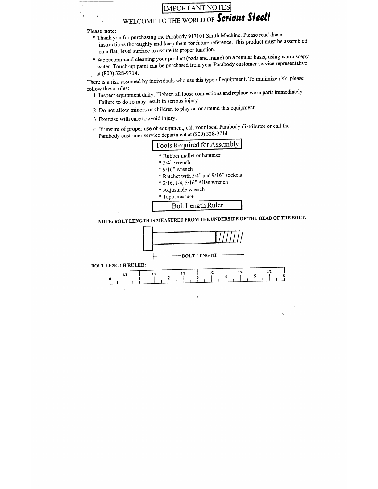
| Bolt Length Ruler
NOTE: BOLT LENGTH IS MEASURED FROM THE UNDERSIDE OF Tl=l-E H~EAD OF THE BOLT.
iJ!!!iiiil
BOLT LENGTH
BOLT LENGTH RULER:
KEY’
2
3
4
5
6
7
8
9
10
I1
12
13
14
15
PART #
~712002
6711402
6711203
6708901
6711601
6711701
6710201
6710102
6710503
6710403
6710803
6709001
6709901
6709603
6675501
DESCRIPTION
BEARING HOUSING
SAFETY STOP
LOWER SUPPORT
SLEEVE ASS~LY
LEFT SAFETY HOOK
RIGHT SAFETY HOOK
SMITH BAR
BAR STOP
LEFT UPRIGHT
RIGI-1T UPRIGHT
UPPER SUPPORT
CHROME ANGLE
80" GUIDE ROD
COUNTER WEIGHT
PLATE HOLDER
PARTS LIST
QTY
KEY
PART #
DESCRIPTION
2
16
3102937
1/2 ) 4-.1/2" BOLT
2
17
3102917
1/2 X4" BOLT
1
18
3102933
3/8 X 2" BOLT
2
19
3103003
5/8 X I-1/4’ SHOULDER BOLT
1
20 3102502
11~ " WASHER
1
21
3102801
1/2" LOCK N’IYr
1
22
3102802
318" LOCK NlYr
2
23
3203001
2" SlJA.I?’I" COLLAR
1
24
3203002
1" SHAI:T COLLAR
1
25
3202901 1-1/2" 1 J tRUST BEARING
1
26
6708501
CAB"~ ASSENtBLY
2
27 3116101
4-] PULLEY
2
28 6714501
8’; 1" GLIDE
2
29
6695801 2-1/2" oD 7,UBBER BUMPER
QTY[
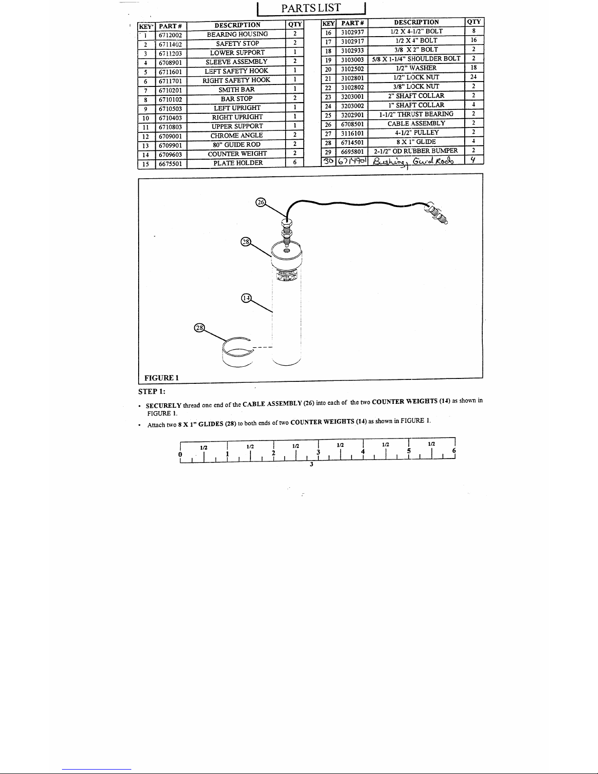
FIGURE I
STEP 1:
¯ SECURELY thread one end of the CA.BLE .ASSEMBLY (26) into each of the two COUNTER ’WEIGHTS (14) as shown
FIGURE 1.
¯
Attach two 8 X 1" GLIDES (28) to both ends of t~vo COUNTER WEIGHTS (14) as shown in FIGURE
6
1
[ I I I
0 [ I I
I
I I
3
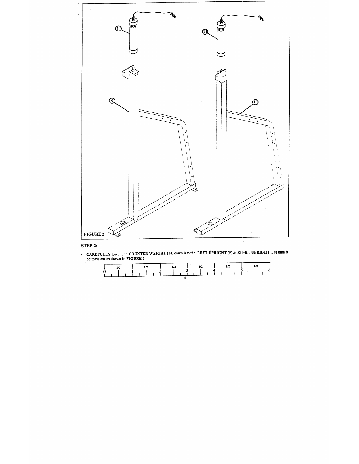
FIGURE 2
STEP 2:
¯
CAREFULLY lower on,e COUNTER WEIGHT (14) do~-n into the LEFT UPRIGHT (9) & RIGBT UPR][GHT (10) untiI
bottoms out as sho~vn in FIGURE 2.
5 64 I l J_l
I I I
3
I I 1 I
4
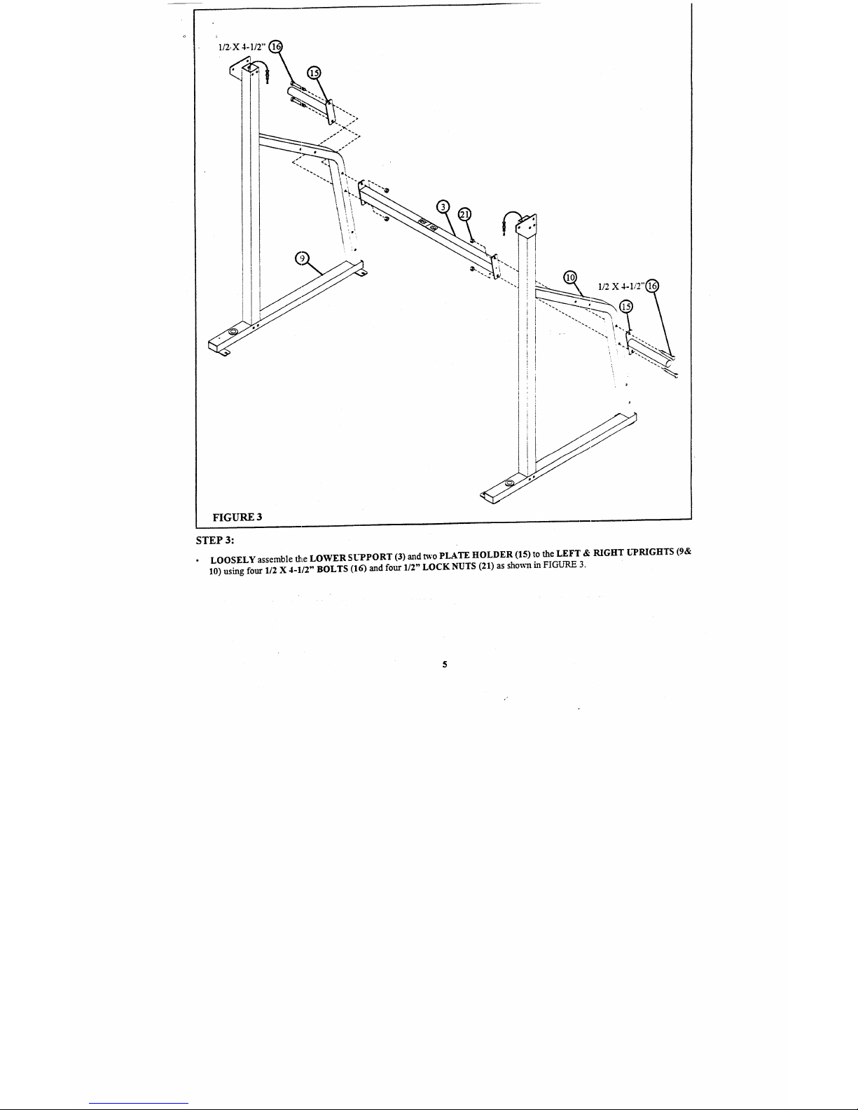
FIGURE 3
STEP 3:
¯
LOOSELY assemble the LOWER SUPPORT (3) and ~’o PLATE HOLDER (15) to the LEFT & RIGHT UPRIGHTS
10) using four 1/2 X 4-1/2" BOLTS (16) and four 1/2" LOCK NUTS (21) as shown in FIGURE
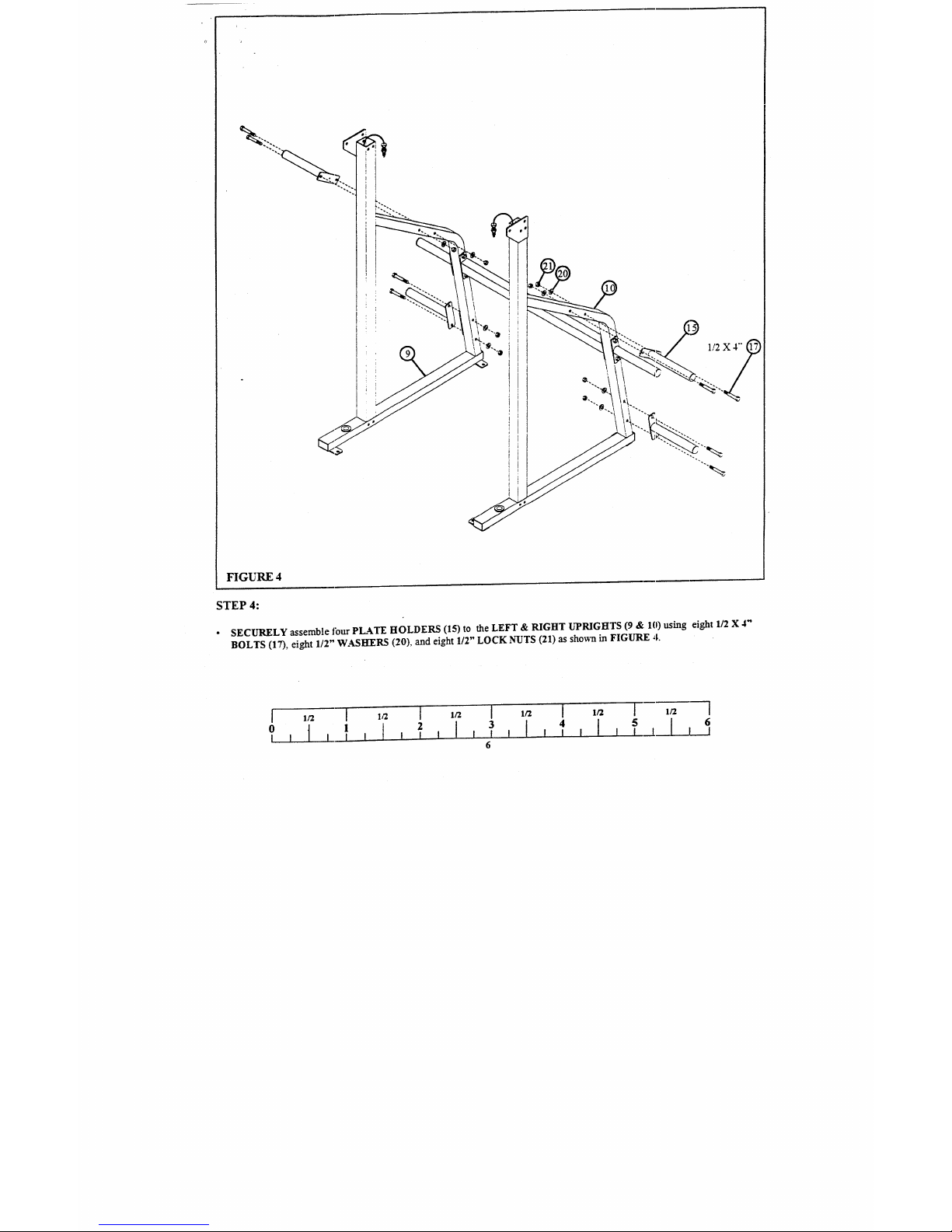
FIGURE 4
STEP 4:
¯
SECURELY assemble fottr PLATE HOLDERS (15) to the LEFT & RIGHT UPRIGHTS (9 & 10) using eight 1/2
BOLTS (17), eight 1/2" WASHERS (20), and eight 1/2" LOCK N-t~TS (21) as sho~a in FIGURE
 Loading...