

Serious Steel
835102 HIP SLED
ASSEMBLY INSTRUCTIONS
I
Part # 6754601
I I
1 Revision: 5/24/00
I IMPORTANT NOT ,ES
I
~
WELCOME TO THE WORLD OF ~l~iOU$ ~t~t~.
Please note:
* Thank you for purchasing the Parabody 835102 HIP SLED. Please read these instructions
thoroughly and keep them for future reference. This product must be assembled on a flat, level
surface to assure its proper function.
* We recommend cleaning your product (pads and frame) on a regular basis, using warm soapy
water. Touch-up paint can be purchased from your Parabody customer service representative
at (800) 328-9714.
There is a risk assumed by individuals who use this type of equipment. To minimize risk, please
follow these rules:
1. Inspect equipment daily. Tighten all loose connections and replace worn parts immediately.
Failure to do so may result in serious injury.
Do not allow minors or children to play on or around this equipment.
2.
3. Exercise with care to avoid injury.
4. If unsure of proper use of equipment, call your local Parabody distributor or call the
Parabody customer service department at (800) 328-9714.
5. Consult a physician before beginning any exercise program.
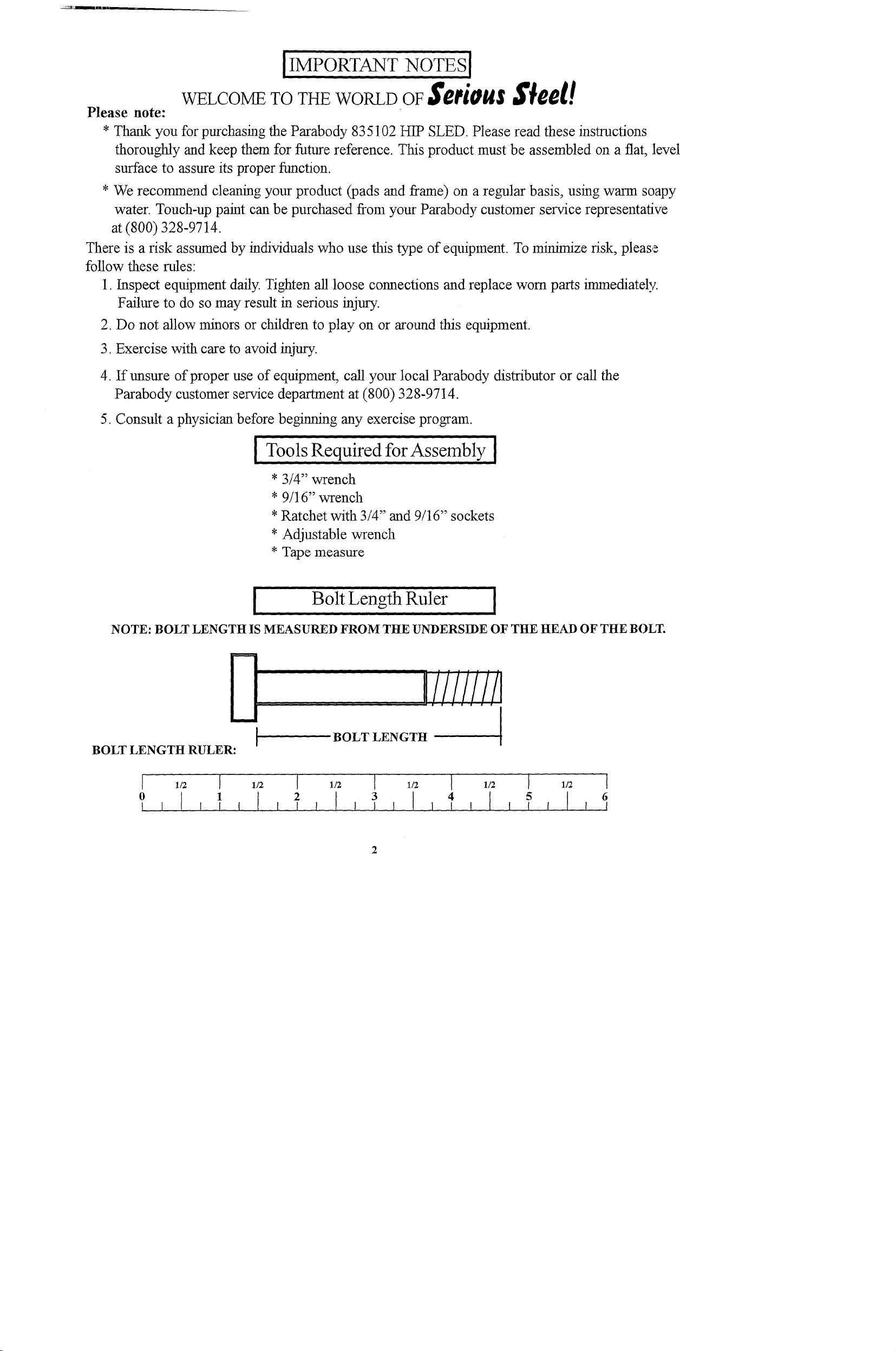
I Tools Required for Assembly I
* 3/4" wrench
* 9/16" wrench
*Ratchet with 3/4" and 9/16’" sockets
* Adjustable wrench
* Tape measure
Bolt Length Ruler
NOTE: BOLT LENGTH IS MEASURED FROM THE UNDERSIDE OF THE HEAD OF THE BOLT.
,
BOLT LENGTH RULER:
BOLT LENGTIt I
2

PARTS LIST
KEY
17
19
2O
21
22
23
24
PART #
1
6504903 ~3ASE
2
6506803’ ~ PLATFORM SLEEVE
6507403 PAD SUPPORT
4
6507703
5
6507803 LEFT HANDLE
6
6505403 REAR UPRIGI2IT ......
7
6505902 CARRIAGE STOP BAR
8
6504103 LE~T RAIL
9
6504203
10
6504402 FOOT PLATE
6504702 PLATFORM
11
6506602
650~002
14
6521202
15.
6534302 PAD STOP
16
6501402
6509201 SHOULDER PAD
6666901 SEAT PAD
18
6667301 BACK PAD
6500501
6500601 2" DIA. WI~EL
3103’104 1 X’5" GRIP
3116001 1-1/4" SQ. RUBBER BUM~ER
DES CRIPTION
RIGHT HANI~L~ ’
RIGHT RAIL
PLATFORM ADJUSTMENT
WEIGHT SUPPORT
ADJ. WHEEL BRACKET
CARRIAGE
3" DIA. WHEEL
1 25
1 26
2 27
1 28
1 29
1 30
2 31
1 32
1
1 34
1 35
1 36
1 37
2
1 39
1 40
2 ’41"
1 42’
1 43
4 ’44’
4 45
2
2 47
2
33
38
46
PART # DES CRIPTION
6270501 4 X 14" NON-SKID STRIP
6405201
6416601
6467001
3102501
3102601
1102802
3102502
3102801
3102804
3102’~09
3102933 3/8 X 2" BOLT
3102904 ’ ’~/8- X3"BOLT
3102935 3/8 X 4-1/2" BOLT
3202101 1/2 X 1-1/4" BOLT
3102953 1/2 X 2-3/4" BOLT ’
3102918 1/2 X 3-1/4" BOLT
3102917 1/2 X 4" BOLT
3102937 1/2 X 4-1/2" BO’LT
~ 102944 i/2 X 5" BOLT
3110002 1-1/4" ROLL PIN
6020601 1/2" FLANGE ’BEARII~G’
6466901
1/2" LOW HEIGHT LOCK NUT
2" SQ. END CAP
1-1/2" X 3/4" PARAGLIDE
2" SQ. COVER CAP
3/8" WASHER
3/8" LOCK WASHER
3/8" LOCK NUT
1/2" WASHER
1/2" LOCK NUT
3/8 X 1" BOLT
1/2" DIA. SPRING PIN
1
8
1
2
24
8
8
32
14
8
2
4
8
2
’2
2
6
2
8
2
2
8
2
X 3-1/4"
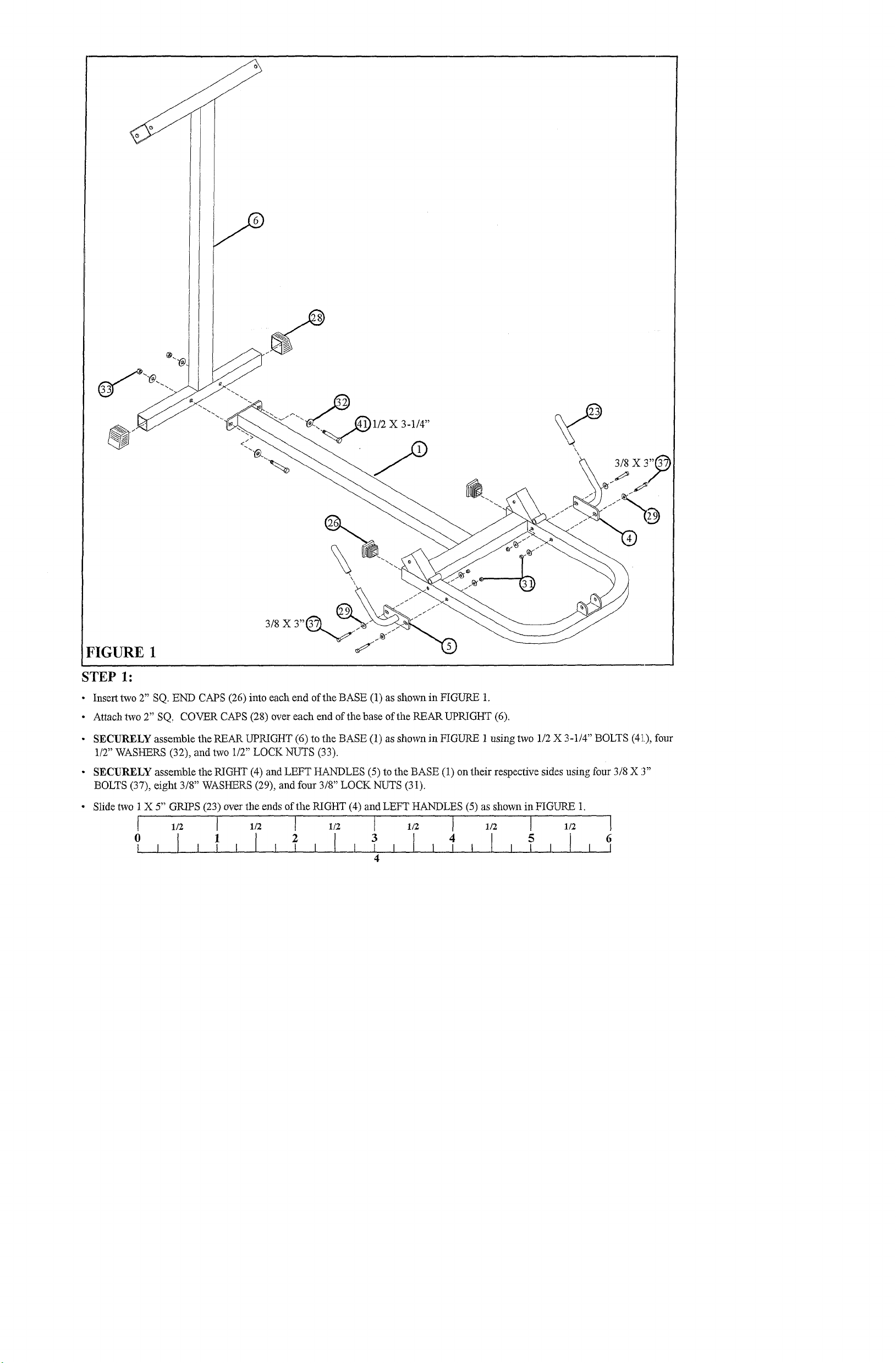
FIGURE 1
STEP 1:
¯
Insert two 2" SQ. END CAPS (26) into each end of the BASE (1) as shown in FIGURE
¯
Attach two 2" SQ, COVER CAPS (28) over each end ofthebase of the REAR UPRIGHT (6).
¯
SECURELY assemble the PEAK UPP,_IGHT (6) to the BASE (1) as shown in FIGURE 1 using two 1/2 X 3-1/4" BOLTS (41.),
1/2" WASHERS (32), and two 1/2" LOCK NUTS (33).
¯
SECURELY assemble the P,_IGHT (4) and LEFT HANDLES (5) to the BASE (1) on their respective sides using four 3/8
BOLTS (37), eight 3/8" WASHERS (29), and four 3/8" LOCK NUTS (31).
¯ Slide two 1 X 5" GRIPS (23) over the ends of the RIGHT (4) and LEFT HANDLES (5) as shown in FIGURE
6
_LLL
_LLLL
LLLLLLLLLLLLLL
_LLLLLLLLLLLLLLLLL
.LLLLLLLLLLLLLLLLLLLLLLLL
LLLLLLLLLLLLLLLLLLLLL
LLLLLLLLLLLLLLLLLLLLLLLLLLLLLLLLLLLL
.LLLLLLLLLLLLLLLLLLLLLLLLLLLLLLLLLLLL[
LLLLLLLLLLLLLLLLLLLLLLLLLLLLLL
LLLLLLLLLLLLLLLLLLLLLLLLLLLLLLLLLLLLL
_LLLLLLLLLLLLLLLLLLLLLLLLLLLLLLLLLLLL[
_LLLLLLLLLLLLLLLLLLLLLLLLLLLLLLLLLLLLL
LLLLLLLLLLLLLLLLLLLLLLLLLLLLLL
LLLLLLLLLLLLLLLLLLLLLLLLLL
L
LLLLLLLLLLLLLLLLL
LLLLLLLLLLLLLLLL
_LLLLLLLLL
L
~1/2 X 5"
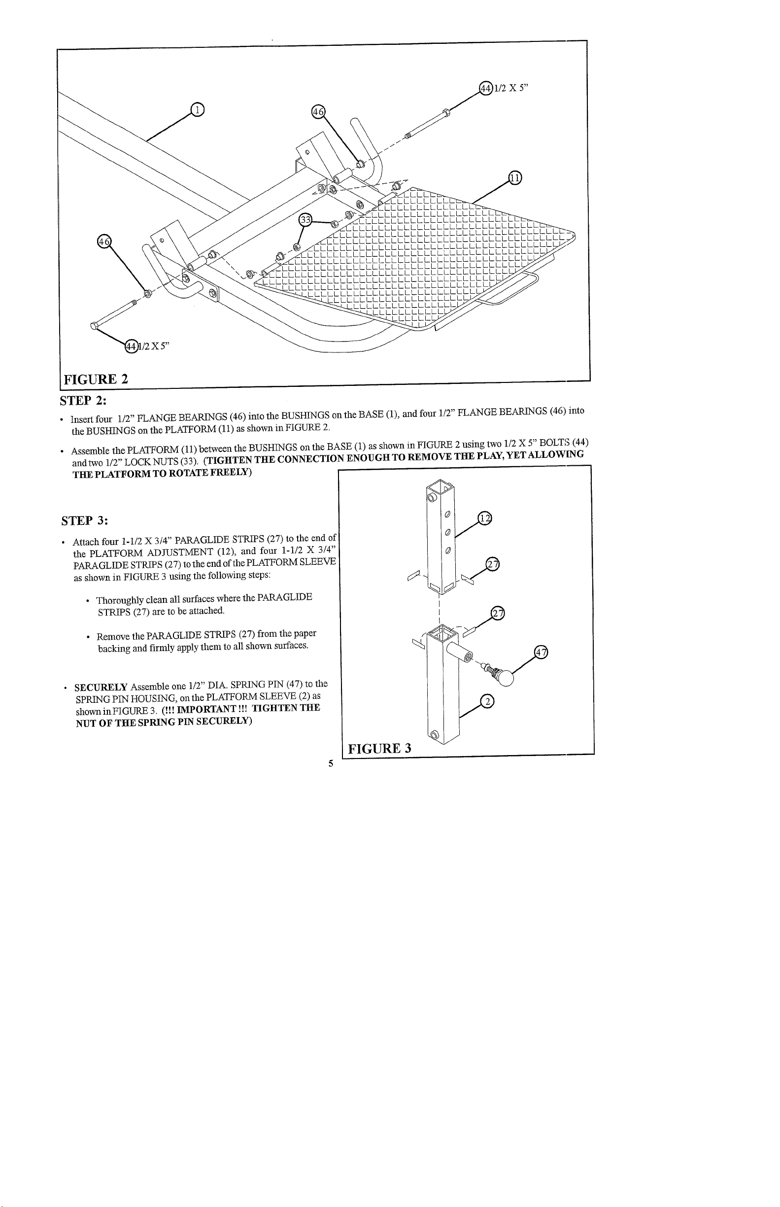
FIGURE 2
STEP 2:
¯
Insert four 1/2" FLANGE BEARINGS (46) into the BUSHINGS on the BASE (1), and four 1/2" FLANGE BEARINGS (46)
the BUSHINGS on the PLATFORM (11) as shown in FIGURE
¯ Assemble the PLATFORM (11) between the BUSHINGS on the BASE (1) as shown in FIGURE 2 using two 1/2 X 5" BOLT’3
andtwo 1/2 LOCKNU S (33). (TIGHTEN THE CONNECTION ENOUGH TO REMOVE THE PLAY, YET ALLOWING
THE PLATFORM TO ROTATE FREELY)
" T
STEP 3:
¯
Attach four 1-1/2 X 3/4" PARAGLIDE STRIPS (27) to the end
the PLATFORM ADJUSTMENT (12), and four 1-1/2 X 3/4"
PARAGLIDE STRIPS (27) to the end of the PLATFORM SLEEVE
as shown in FIGURE 3 using the following steps:
¯ Thoroughly clean all surfaces where the PARAGLIDE
STRIPS (27) are to be attached.
¯
Remove the PARAGLIDE STRIPS (27) from the paper
backing and firmly apply them to all shown surfaces.
SECURELY Assemble one 1/2" DIA. SPRING PIN (47) to the
SPRING PIN HOUSING, on the PLATFORM SLEEVE (2)
showninFIGURE 3. (!!! IMPORTANT !!! TIGHTEN THE
NUT OF THE SPRING PIN SECURELY)
FIGURE 3
_LLLL
.LLLLI
1/2 X 4"~
_LLLL
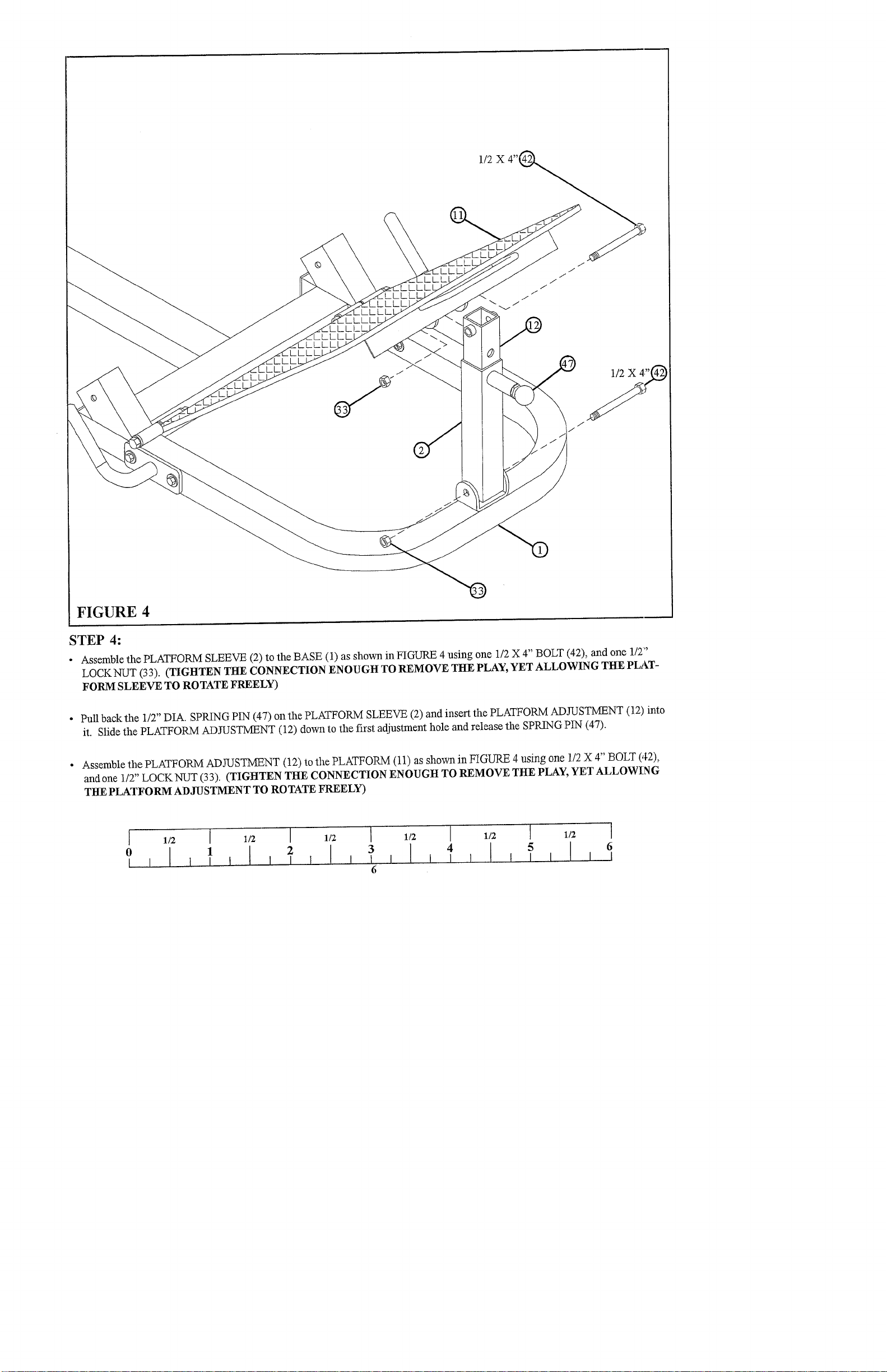
FIGURE 4
STEP 4:
¯ Assemble the PLATFORM SLEEVE (2) to the BASE (1) as shown in FIGURE 4 using one 1/2 X 4" BOLT (42), and one
LOCKNUT (33). (TIGHTEN THE CONNECTION ENOUGH TO REMOVE THE PLAY, YET ALLOWING THE PLATFORM SLEEVE TO ROTATE FREELY)
¯ Pull back the 1/2" DIA. SPRING PIN (47) on the PLATFORM SLEEVE (2) and insert the PLATFORM ADJUSTMENT (12)
it. Slide the PLATFORM ADJUSTMENT (12) down to the first adjustment hole and release the SPRING PIN (47).
Assemble the PLATFORM ADJUSTMENT (12) to the PLATFORM (11) as shown in FIGURE 4 using one 1/2 X 4" BOLT (42),
and one 1/2" LOCKNUT (33). (TIGHTEN THE CONNECTION ENOUGH TO REMOVE THE PLAY, YET ALLOWING
THE PLATFORM ADJUSTMENT TO ROTATE FREELY)
1/2 [
I I I
1/2 I 1/2 [
1/2
1
[ I I
6
1/2 I 1/2
I
5 6

’@1/2 X 4-1/2"
I
I
I
I
/
I
I
I
)
I
I
!
!
/
/
/
/
I
~
3/8 X 4-1/2"@
FIGURE 5
STEP 5:
LOOSELY assemble the LEFT (8) and RIGHT RAILS (9), along with the SEAT PAD (18) to the BASE (1) as shown in
¯
using two 3/8 X 4-1/2" BOLTS (38), two 3/8" LOCK WASteRS (30), and two 3/8" WASHERS (29). Temporarily asselnble
RAILS to the REAR UPRIGHT (6) using two 1/2 X 4-1/2" BOLTS (43) to aid in the assembly of this step.
7

1/2 X 4-1/2 ~
FIGURE 6
STEP 6:
¯ Insert four 2" SQ. END CAPS (26) into the each end of the CARRIAGE (16) as shown in FIGURE
SECURELY assemble four 3" DIA. WHEELS (20) to the sides of the CARRIAGE (16) as shown in FIGURE 6 using
¯
4-1/2" BOLTS (43), eight 1/2" WASHERS (32), and four 1/2" LOW HEIGHT LOCK NUTS (34).
¯ Attach one 4 X 14" NON SKID STRIP (25) to the CARRIAGE (16) as shown in FIGURE
I 1/2 I 1/2 I 1/2 I 1/2 I 1/2 I 1/2
6

LOW HEIGHT
1/2 X 2-3/4"~
~3/8
X 2"
[GURE 7
STEP 7:
¯
SECURELY assemble two 2" DIA. WHEELS (21) to the BRACKETS onthe left side of the CARRIAGE (16) as shown
FIGURE 7 using two 3/8 X 2" BOLTS (36), four 3/8" WASHERS (29), and two 3/8" LOCK NUTS (31).
Assemble the two ADJ. WHEEL BRACKETS (14) to the right side of the CARRIAGE (16) as shown in FIGURE 7 using two
¯
X 2-3/4" BOLTS (40), two 1/2" WASHERS (32), and two 1/2" LOW I-I~, IGHT LOCK NUTS (34). (NOTE: TIGHTEN BIIACK-
ETS SECURELY TO THE CARRIAGE, THEN BACK NUT OFF 1/2 TURN TO ALLOW FORADJUSTMENT IN A
LATTER S TEP).
SECURELY assemble two 2" DIA. WHEELS (21) to the ADJ. WHEEL BRACKETS (14) on the right side of the CARRIAGE
¯
(16) as shown in FIGURE 7 using two 3/8 X 2" BOLTS (36), four 3/8" WASHERS (29), and two 3/8" LOCK NUTS
9
Q1/2X4-1/2"
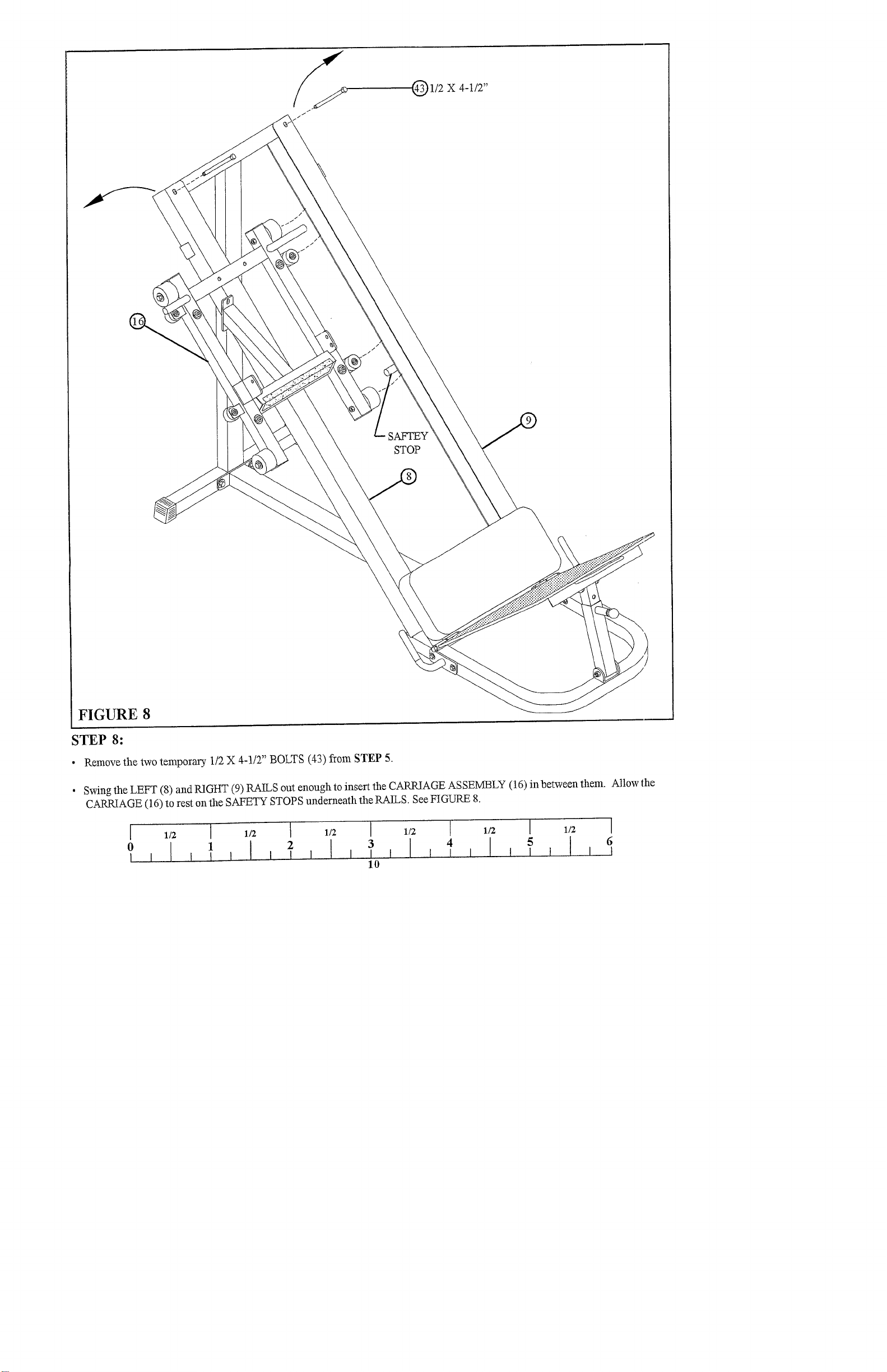
FIGURE 8
STEP 8:
¯ Remove the two temporary. 1/2 X 4-1/2" BOLTS (43) from STEP
SAFTEY
STOP
¯ Swing the LEFT (8) and RIGHT (9) RAILS out enough to insert the CARRIAGE AS SEIV~LY (16) in between
CARRIAGE (16) to rest on the SAFETY STOPS underneath the RAILS. See FIGURE
1/2 ] 1/2 I
1
I I I
1/2 [ 1/2
]
1/2 I
2
I
I
I I
10
1/2
Allow the
I
6

Q1/2
X 4-1/2"
REVERSE VIEW
FOR ASSEMBLY
FIGURE 9
;TEP 9:
SECURELY reassemble the LEFT (8) and RIGHT (9) RAILS to the REAR UPRIGHT (6) as shown in FIGURE 9 using the two
¯
X 4-1/2" BOLTS (43), four 1/2" WASHERS (32), and two 1/2" LOCK NUTS (33). (!!! IMPORTANT !!! BEFORE TIGttTENING
MOVE THE RAILS IN AS FAR AS POSSIBLE)
¯ SECURELY tightenthe two 3/8 X 4-1/2" BOLTS (38) holding the SEAT PAD (18) from STEP 5. (!!! IMPORTANT !!! BEFORE
TIGHTENING MOVE THE RAILS IN AS FAR AS POSSIBLE)
¯ To adjust the side to side movement of the CARRIAGE (16), start by sliding the CARRIAGE (16) as far to the lefI as possible
inside the RAILS (8 & 9). Adjust the ADJ. WHEEL BRACKETS (14) out until the 2" DIA. WHEELS (21) contact the
RAIL (9). SECURELY tighten bolt connection. See FIGURE 9 and REVERSE CARRIAGE VIEW.
11
X 4-1/2"
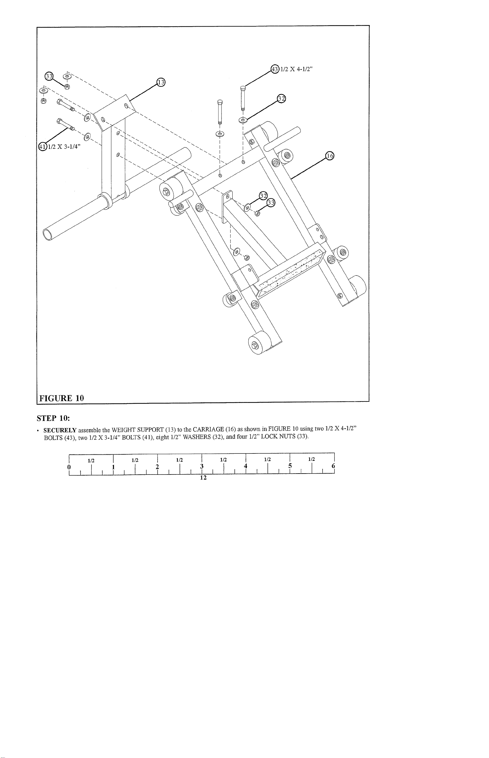
FIGURE 10
STEP 10:
¯
SECURELY assemble the WEIGHT SUPPORT (13) to the CARRIAGE (16) as shown in FIGURE 10 using two 1/2 X 4-1/2"
BOLTS (43), two 1/2 X 3-1/4" BOLTS (41), eight 1/2" WASHERS (32), and four 1/2" LOCK NUTS
1/2 I 1/2 [ 1/2 [ 1/2 t 1/2 t 1/2 I
4 5 6
12

1/2 X 3-1/4"
FIGURE 11
STEP 11:
¯ Insert two 2" SQ. END CAPS (26) into the ends of each PAD SUPPORT (3) as shown in FIGURE
¯
SECURELY assemble the two PAD SUPPORTS (3) to the CARRIAGE (16) as shown in FIGURE 11 using two 1/2 X 3-1/4"
BOLTS (41), four 1/2" WASHERS (32), and two 1/2" LOCKNUTS (33).
¯
SECURELY assemble two SHOULDER PADS (17) to the PAD SUPPORTS (3) on the CARRIAGE (16) as shown in FIGURE
using four 3/8 X 3" BOLTS (37), four 3/8" LOCK WASHERS (30), and four 3/8" WASHERS (29).
13

LLLLL
_LLLL
__LLLL
__LLLL
__LLLL
__LLLL
__LLLL
~L_LLL
__LLL
__LLL
_LLLL
_LLLL
LL
LLL
LLLL
LLLL
LLLL
LLLL
LLLL
LLLL
LLLL
LLLL
LLLL
LLLL
LLLL
LLL
~L
L
_LLLLL
L
_LLLLL
_LLLLL_
_LLLLL_
_LLLLL_
_LLLLL_
_LLLLL_
_LLLLL_
_LLLLL_
_LLLLL_
_LLL
_LLL
_L
LLL
LLLL
L
L_
LLL
LLLL
LLLL
LLLL
LLLL
LLLL
LLLL
LLLL
LLLL
LLLL
LLLL
LLLL
LL
L
FIGURE 12
STEP 12:
¯ Attach two 1-1/4" SQ RUBBER BUM~ERS (24) to the ends of the ANGLES of the FOOT PLATE (10) as shown in FIGURE
¯
SECURELY assemble one 1/2" DIA. SPRING PIN (47) to the SPRING PIN HOUSING on the FOOT PLATE (10) as shown
FIGURE 12. (! !! IMPORTANT !! ! TIGHTEN THE NUT OF THE SPRING PIN SECURELY)
1/2 I 112 I 1/2 I 1/2 I 1/2
2
I I I I
I I I I I I
14
I 1/2

FIGURE 13
STEP 13:
¯
Assemble the FOOT PLATE (10) to the CAR~AGE (16) as shown in FIGURE 13, using two 1/2 X 1-1/4" BOLTS (39), two
WASHERS (32), and two 1/2" LOW HEIGHT LOCK NUTS (34). (TIGHTEN TI-IE CONNECTION COMPLETELY,
BACK TI-IE NUTS OFF 1/4 TURN)
15

S
BUSHING
FIGURE 14
STEP 14:
¯
To assemble the CARRIAGE STOP BAR (7) to theside of the LEFT RAIL (8), start by inserting the top of the BAR (7) imo
BUSHING at the top of the RAIL as far as possible, then lower the BAR (7) into the SURE-LOC BUSHING at the bottom ol." the
RAIL. (MAKE SURE THE STOP PEGS ARE VERTICAL), then insert one 1-1/4" ROLL PIN (45) into the hole at the tc,p
the BAR (7). (DO NOT LET THE ROLL PIN PROTRUDE BENEATH THE BAR) Repeat this step on the RIGHT RAIL
¯ Slide two 1-1/4 X 5" GRIPS (22) over the HANDLES on the CARRIAGE STOP BARS (7) as shown in FIGURE
16

FIGURE 15
3/8 X 1"~
STEP 15:
¯
SECURELY assemble the PAD STOP (15) to the BACK PAD (19) as shown in FIGURE 15 using t~vo 3/8 X 1" BOLTS (35)...
3/8" LOCK WASHERS (30), and two 3/8" WASHERS (29).
MAKE SURE ALL CONNECTIONS ARE SECURELY TIGHTENED.
17

CARRIAGE
STOPS
SURE-LOC~
BUSHING ""
°
35°~40°,45
FIGURE 16
STEP 16:
¯ The PLATFORM (11) can adjust into three positions: 35, 40, and 45 degrees
¯
The HIP SLED was designed ~vith the SURE-LOC SYSTEM for ultimate safety. To activate the CARRIAGE STOP BARS (7)from
either the LEG PRESS or HACK SQUAT position, begin by moving the CARPJAGE (16) up. Grasp the (HANDLES or BA~
the CARRIAGE STOP BA~S (7) and (push or pull) up and rotate them out. Now the stops are out of the ~vay to perform
exercise.
¯
To stop the CARRIAGE (16) on one of the three carriage stops simply rotate the CARRIAGE STOP BARS (7) back up and allow
them to drop down into the SURE-LOC SYSTEM.
I 1/2 [ 1/2 I 1/2
2 3 4
I 1/2
18
I 1/2
] 1/2 [
5 6

HANLDE
FIGURE 17
STEP 17:
¯
To perform LEG PRESSES, center the BACK PAD (19) down on top of the PLATFORM (11) and lock the PAD STOP (15)
back of the BACK PAD (19) behind the PLATFORM HANDLE then rotate the FOOT PLATE (10) on the CARRIAGE (16)
until the SPRING PIN engages the hole
¯
To perform CALF RAISES, move the CARRIAGE (16) to the top carriage stop of the CARRIAGE STOP BAR (7). Place feet
the HORIZONTAL TUBE ofthe CARRIAGE (16). (WHERE THE NON-SKID STRIP IS LOCATED) (DO NOT ROTATE
THE CARRIAGE STOP BARS DOWN FOR THIS EXERCISE)
To perform HACK SQUATS, make sure that the FOOT PLATE (10) of the CARRIAGE (16) is down. Position the
(19) between the SHOULDER PADS of the CARRIAGE (16). (MAKE SURE THE PAD STOP IS RESTING ABG,VE
THE CROSS TUBE ON TIlE CARRIAGE)
THIS CONCLUDES THE ASSEMBLY OF THE 835102 HIP SLED.
19
 Loading...