

Page 1
781 SWIVEL CABLE KIT
PART # 7123201
REV . A
USER’S GUIDE
1
1CLASS H
WARNING:
Read and follow all directions
for each step to insure proper
assembly of this product.
Version: 781101
Revision: 05/23/01
Page 2
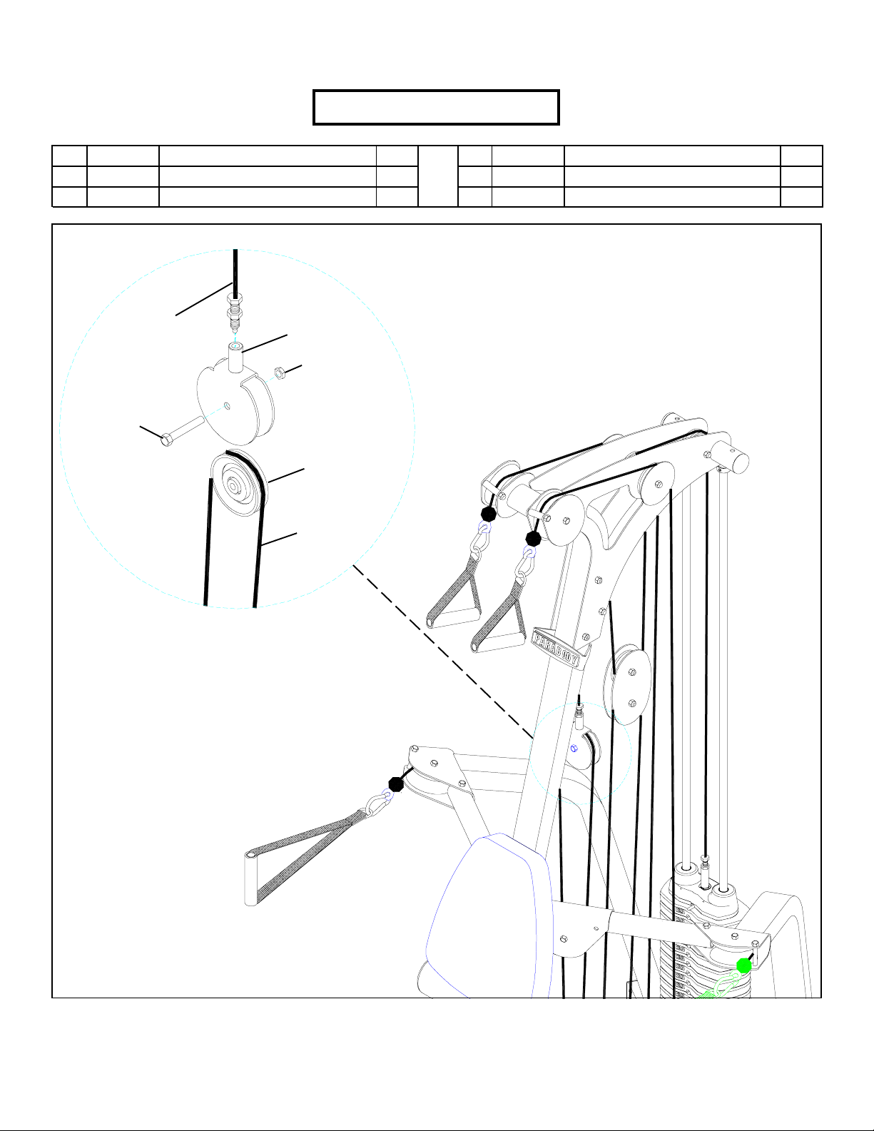
PARTS LIST
KEY
PART #
7118508
1
7122101
2
3/8 X 1-3/4”
BOL T
WEIGHT
ST ACK
CABLE
DESCRIPTION
GUIDE BRACKET
CABLE
PULLEY
BRACKET
3/8” LOCK NUT
PULLEY
ARM
CABLE
QTY
1
2
KEY
3
4
PART #
3102514
3102955
DESCRIPTION
3/8” SAE WASHER
3/8 X 4-1/4” BOLT
QTY
4
2
FIGURE 1
STEP 1:
• Remove PULLEY and PULLEY BRACKET from the 777 GYM SYSTEM. Discard the PULLEY BRACKET. See FIGURE 1.
2
Page 3
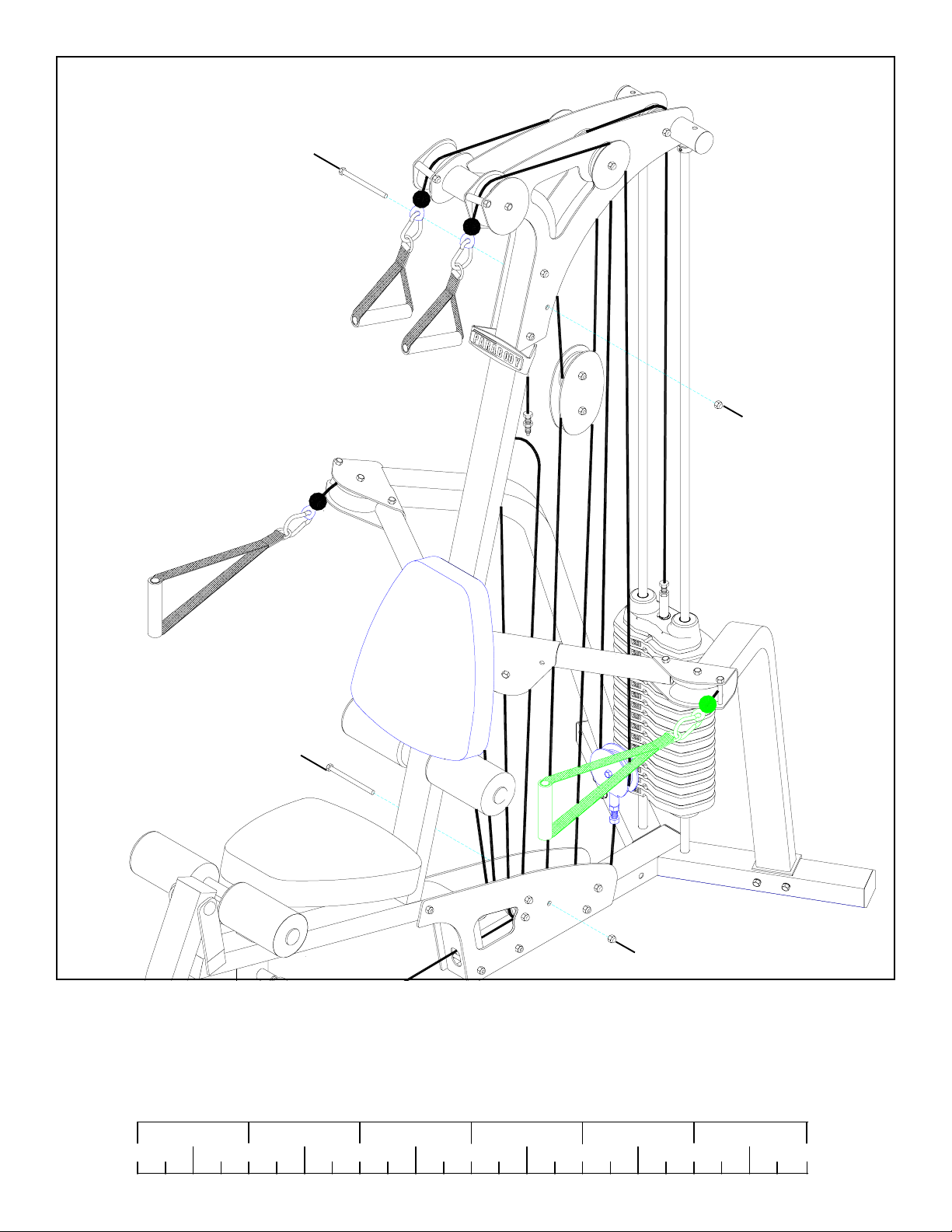
FIGURE 2
3/8 X 3-3/4”
BOL T
3/8” LOCK NUT
3/8 X 3-3/4”
BOL T
3/8” LOCK NUT
STEP 2:
• Remove one 3/8” LOCK NUT and one 3/8 X 3-3/4” BOLT from the TOP and BOTTOM PLATES as shown in FIGURE 2.
Discard the 3/8 X 3-3/4” BOLTS.
1/2 1/2 1/2 1/2 1/2 1/2
0
1
2
345
3
6
Page 4
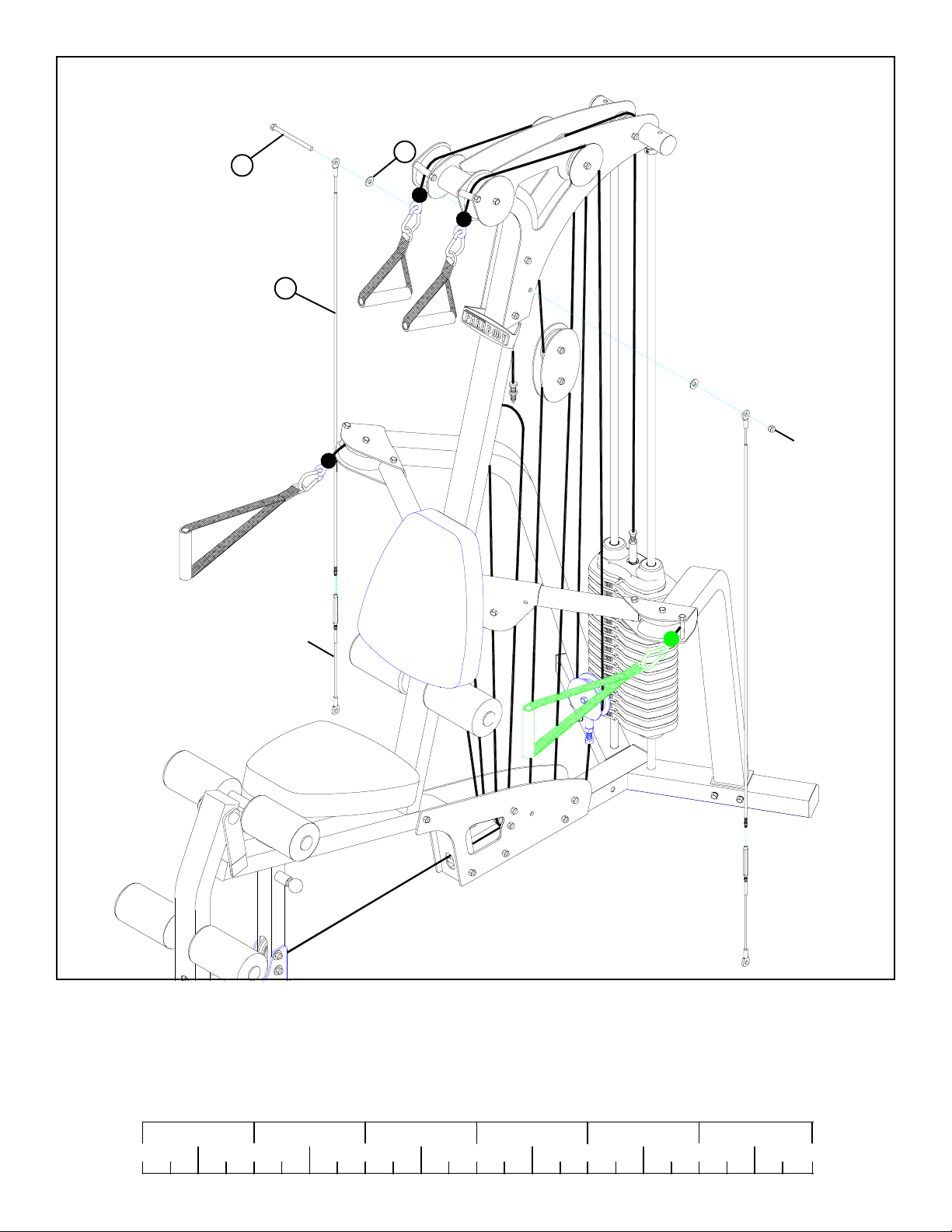
FIGURE 3
3/8 X 4-1/4” 4
3
2
3/8” LOCK
NUT
SHORT
CABLE
STEP 3:
• Assemble the CABLES (2) to the TOP PLATES using one 3/8 X 4-1/4” BOLT (4), two 3/8” SAE WASHERS (3) and one previously removed 3/8” LOCK NUT as shown in STEP 3.
• Disassemble the SHORT CABLE and the turnbuckle on LONG CABLE (2) as shown in FIGURE 3. The SHORT CABLE will be
reassembled later.
1/2 1/2 1/2 1/2 1/2 1/2
0
1
2
345
4
6
Page 5
2
1
SHORT CABLE
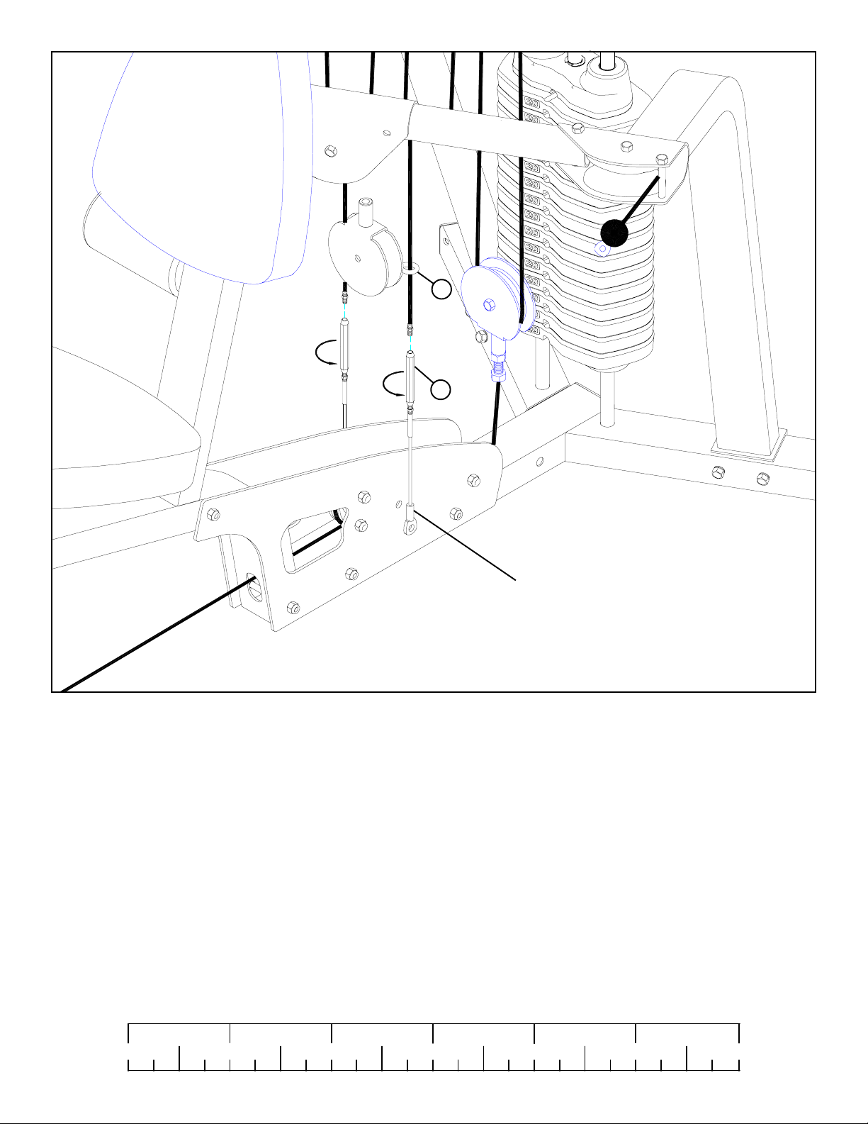
FIGURE 4
STEP 4:
• CAREFULLY slide the GUIDE BRACKET (1) through the CABLES (2) as shown in FIGURE 4.
• Assemble the SHORT CABLE and the turnbuckle to each CABLE (2) as shown in FIGURE 4.
1/2 1/2 1/2 1/2 1/2 1/2
0
1
2
345
5
6
Page 6
WEIGHT
CABLE
3/8 X 1-3/4”
BOL T
ST ACK
2
3/8” LOCK NUT
PULLEY
ARM
CABLE
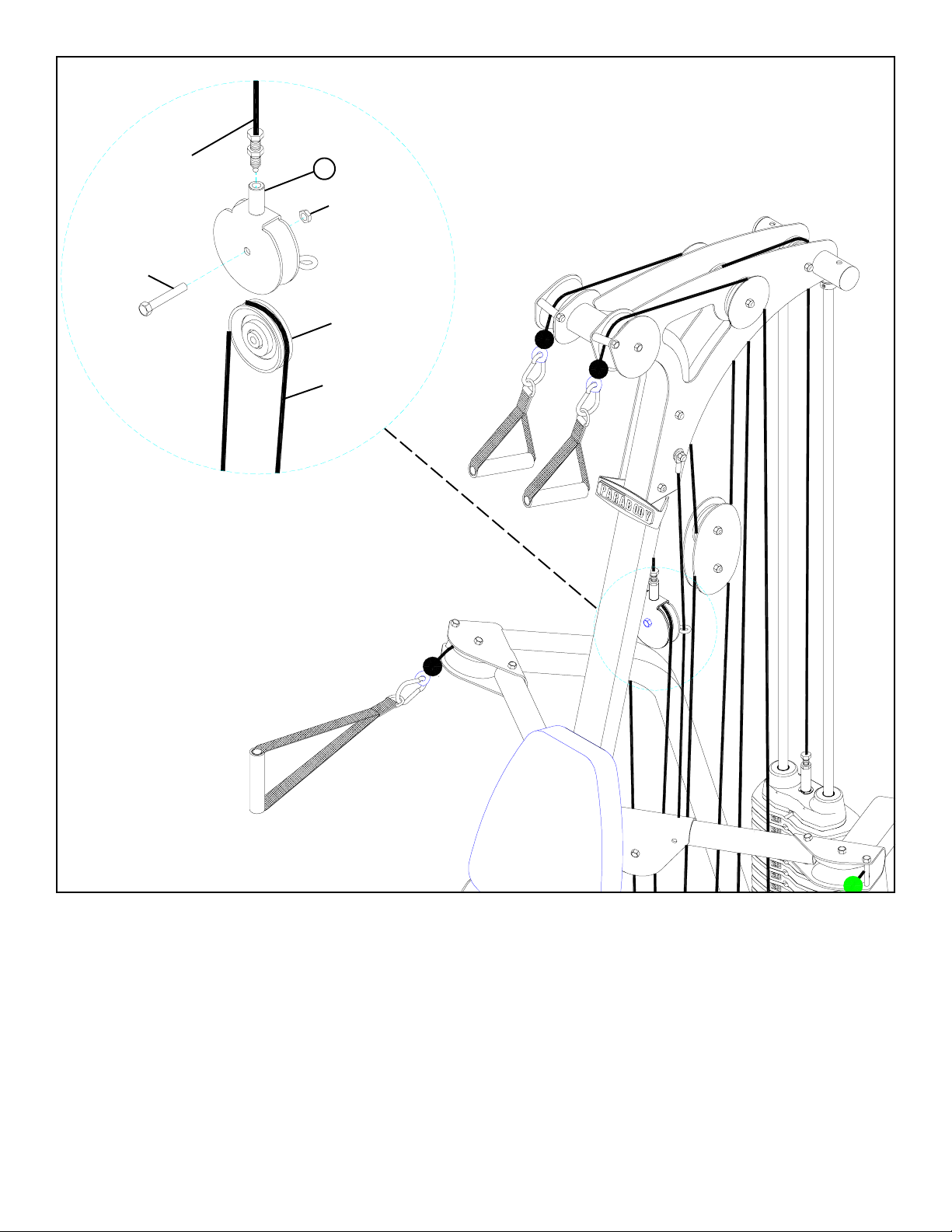
FIGURE 5
STEP 5:
• Slide the GUIDE BRACKET (1) up and reattach the WEIGHT STACK CABLE as shown in FIGURE 5.
• Loop the ARM CABLE around the previously removed pulley and assemble it to the GUIDE BRACKET (1) with the previously
removed hardware as shown in FIGURE 5.
6
Page 7
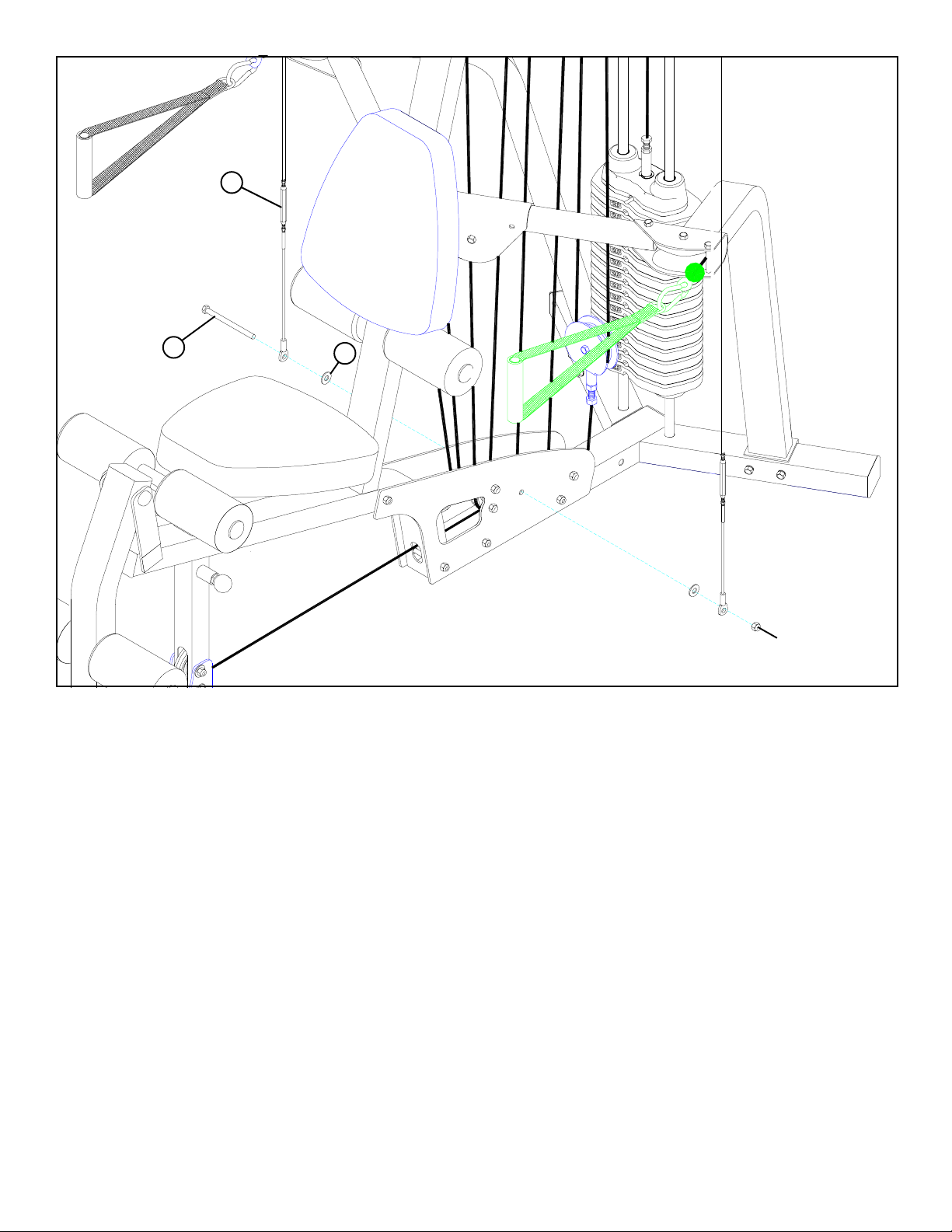
FIGURE 6
2
3/8 X 4-1/4” 4
STEP 6:
• Assemble the CABLES (2) to the BOTTOM PLATES using one 3/8 X 4-1/4” BOLT (4), two 3/8” SAE WASHERS (3) and one
previously removed 3/8” LOCK NUT as shown in STEP 6.
3
3/8” LOCK
NUT
7
Page 8
TURNBUCKLE
JAM NUT
2
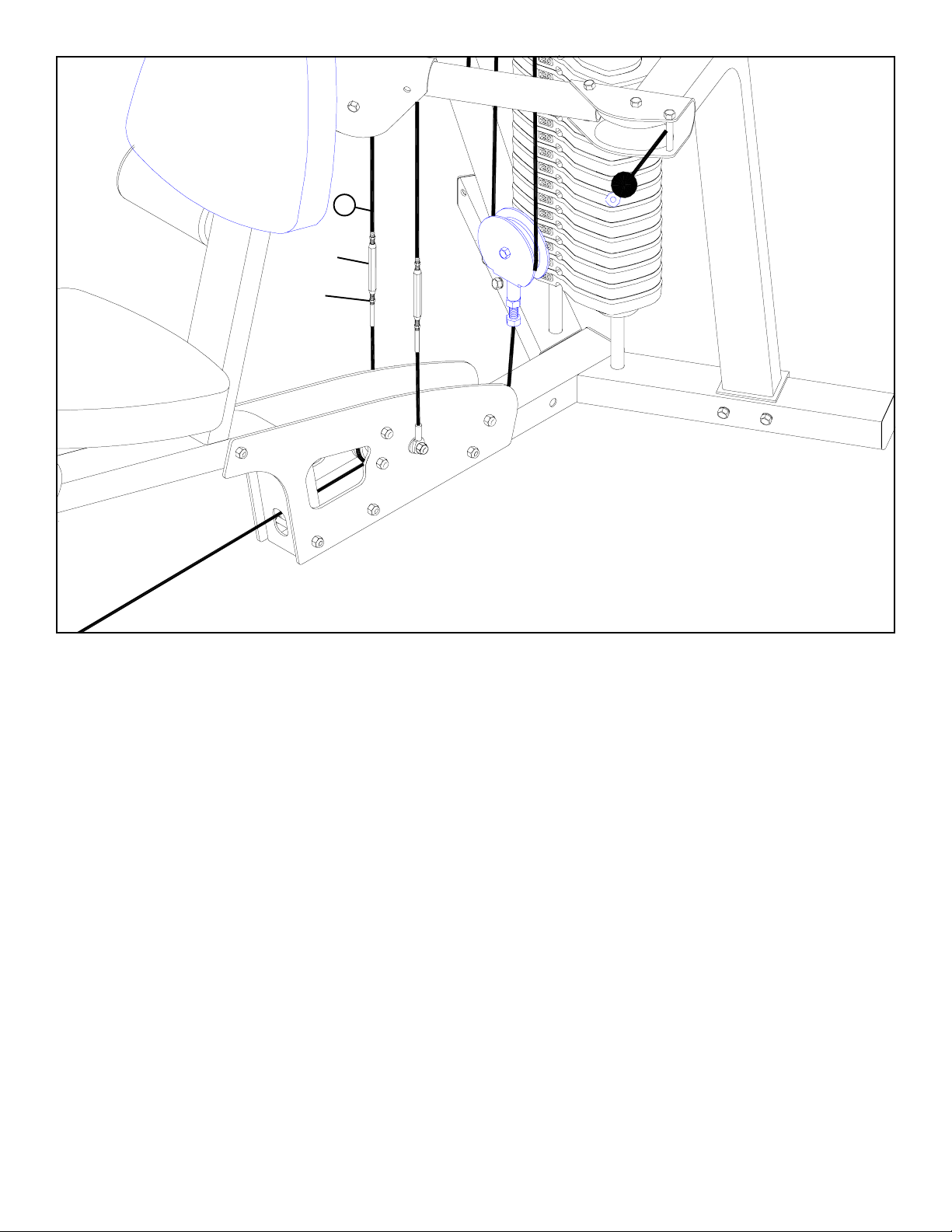
FIGURE 7
STEP 7:
• Adjust the turnbuckle on each CABLE (2) to add tension to the CABLES (2). Secure turnbuckle with the JAM NUTS as shown in
FIGURE 7.
• Refer to the 777 USER GUIDE to adjust tension in the systems cables and tighten all jam nuts securely.
8
 Loading...