

Page 1
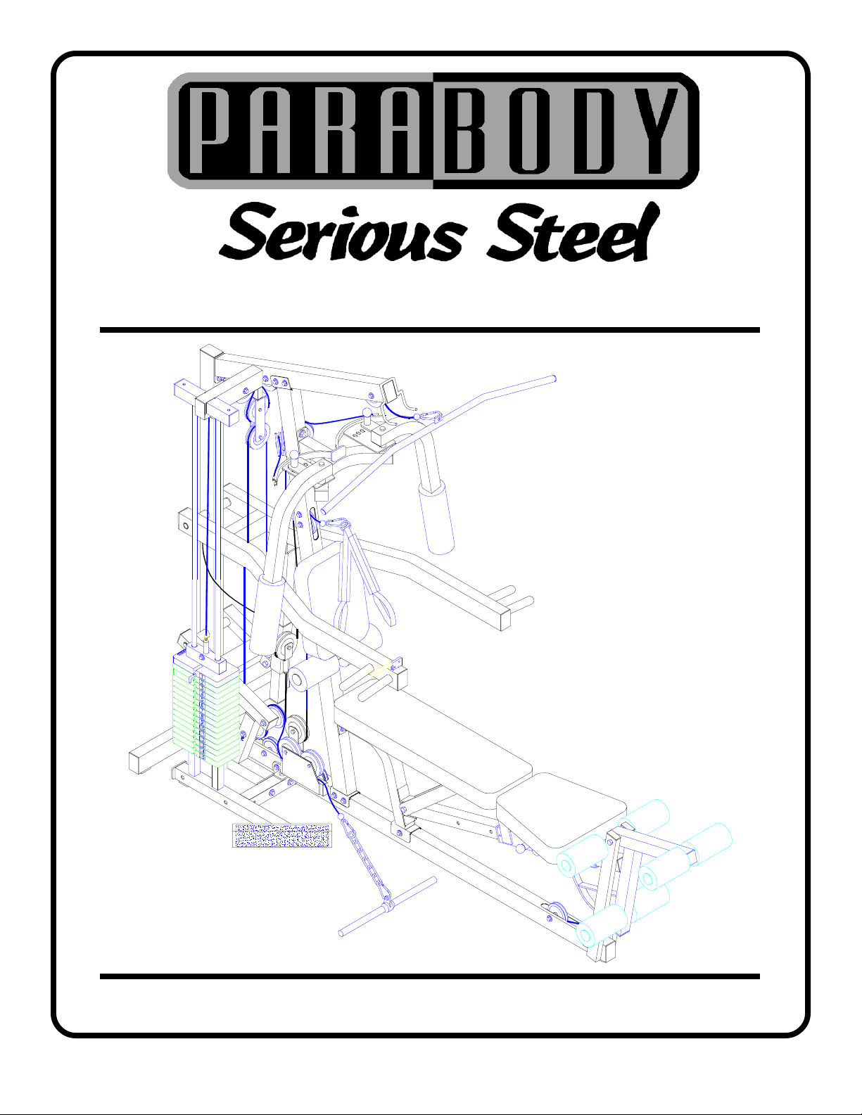
400101 HOME GYM
ASSEMBLY INSTRUCTIONS
1Part # 6693401 Revision: 09/9/98
Page 2
IMPORTANT NOTES
WELCOME TO THE WORLD OF Serious steel!
Please note:
* Thank you for purchasing the Parabody 400101 Home Gym. Please read these
instructions thoroughly and keep them for future reference. This product must be assembled
on a flat, level surface to assure its proper function.
* We recommend cleaning your product (pads and frame) on a regular basis, using warm soapy
water. Touch-up paint can be purchased from your Parabody customer service representative
at (800) 328-9714.
There is a risk assumed by individuals who use this type of equipment. To minimize risk, please
follow these rules:
1. Inspect equipment daily . Tighten all loose connections and replace worn parts immediately.
Failure to do so may result in serious injury.
2. Do not allow minors or children to play on or around this equipment.
3. Exercise with care to avoid injury .
4. If unsure of proper use of equipment, call your local Parabody distributor or call the
Parabody customer service department at (800) 328-9714.
5. Consult your physician before beginning any exercise program.
T ools Required for Assembly
* Rubber mallet or hammer
* 3/4” wrench
* 9/16” wrench
* Ratchet with 3/4” and 9/16” sockets
* 5/32” Allen wrench
* Adjustable wrench
* T ape measure
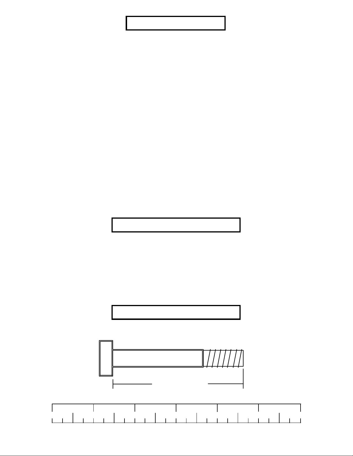
Bolt Length Ruler
NOTE: BOL T LENGTH IS MEASURED FROM THE UNDERSIDE OF THE HEAD OF THE BOLT.
BOL T LENGTH RULER:
1/2 1/2 1/2 1/2 1/2 1/2
0
1
BOLT LENGTH
2
345
2
6
Page 3
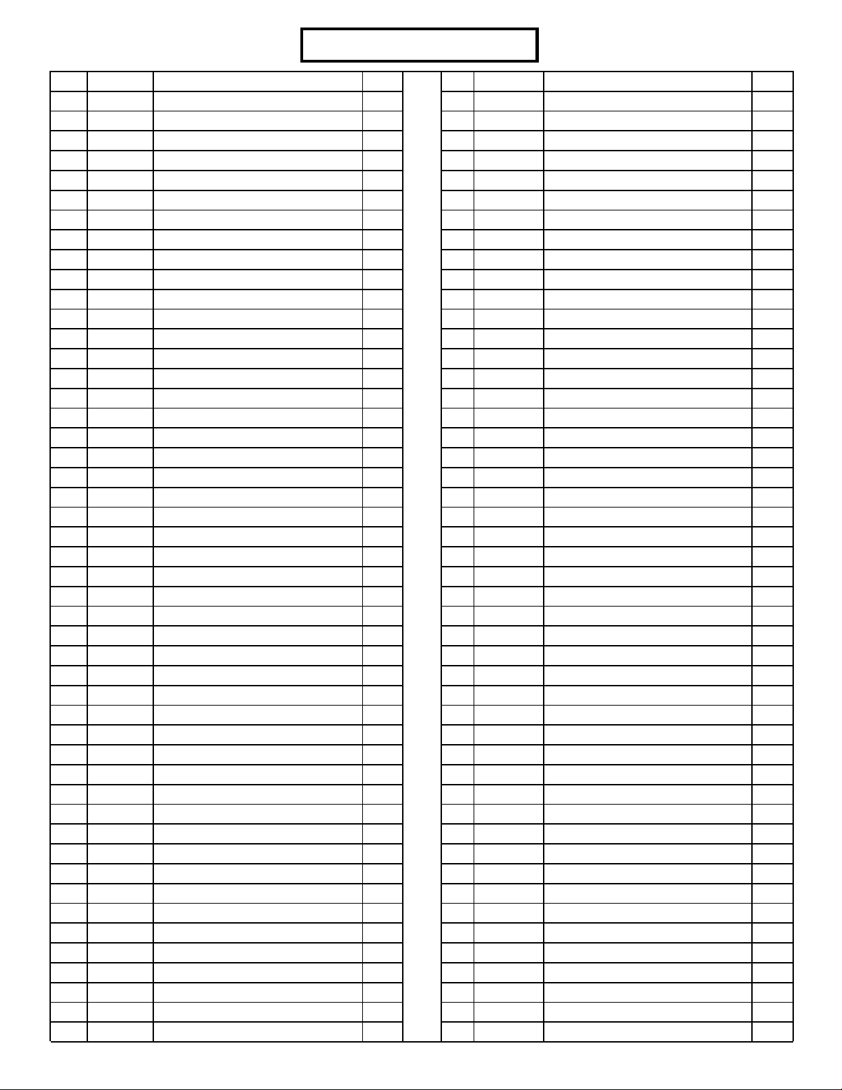
PARTS LIST
KEY
1
2
3
4
5
6
7
8
9
10
11
12
13
14
15
16
17
18
19
20
21
22
23
24
25
26
27
28
29
30
31
32
33
34
35
36
37
38
39
40
41
42
43
44
45
46
47
48
PART #
6746903
6683302
6682803
6679903
6686802
6679503
6678603
6683103
6680402
6682103
6682503
6681303
6680202
6683802
6746803
6680903
6680803
6681902
6532903
6532803
6530203
6594702
6624402
6529702
6275302
6654302
6597402
6681502
6690901
6125102
6194601
6176201
6523401
6375902
3102909
3102924
3102933
3102922
3102904
3102905
3102906
3102910
3102943
3102917
3102937
3102901
6382301
3102802
DESCRIPTION
FRAME SUPPORT
WOLFF SLEEVE
WEIGHT ST ACK BASE
LEG CURL/EXTENSION
PULLEY BRACKET
ADJUSTMENT SLIDE
TOP BOOM
PRESS ARM
PRESS ARM LEVER
BASE
FRONT UPRIGHT
LEVER STOP
RECEIVING TUBE
BACK P AD SUPPOR T
BENCH FRAME
REAR UPRIGHT
BEARING HOUSING
PLATE, 1/4 X 2 X 16-1/2”
PEC ARM RIGHT
PEC ARM LEFT
CENTER PULLEY BRACKET
FLOA TING PULLEY
SWIVEL PULLEY BRACKET
PEC CAM
LA T BAR
33-1/2 X 9-1/2” BACK SEAT PAD
15-1/2 X 10-1/2” PEC SEAT PAD
15-3/4 X 15-1/2” LEG SEAT PAD
3/4 DIA X 1 1” SHAFT
3/4 OD X 16” TUBE
4 X 7” ROLLER PAD
PEC DEC ROLLER P AD
3/4 X 72-3/8” GUIDE ROD
WEIGHT ST ACK SP ACER
3/8 X 1” BOLT
3/8 X 1-3/4” BOLT
3/8 X 2” BOLT
3/8 X 2-3/4” BOLT
3/8 X 3” BOLT
3/8 X 3-3/4" BOLT
3/8 X 4" BOL T
1/2 X 3" BOL T
1/2 X 3-1/2" BOLT
1/2 X 4" BOL T
1/2 X 4-1/2" BOLT
3/8 X 1-1/4” BOLT
WEIGHT PLA TE BUSHING 10CT
3/8” NYLOCK NUT
QTY
1
1
1
1
1
1
1
1
1
1
1
1
1
1
1
1
1
2
1
1
1
2
1
2
1
1
1
1
2
4
8
2
2
2
4
5
4
11
5
2
4
8
5
2
3
1
3
29
KEY
3
49
50
51
52
53
54
55
56
57
58
59
60
61
62
63
64
65
66
67
68
69
70
71
72
73
74
75
76
77
78
79
80
81
82
83
84
85
86
87
88
89
90
91
92
93
94
95
PART #
3102801
3102804
3102501
3102502
3102503
3109602
6686301
6075906
6214401
6533501
6321201
3119201
3119101
3117901
3119401
3118401
3106803
6480301
6020601
6019701
3104901
6416601
6412001
3103801
3105401
6214501
6692601
6405201
6236701
6406401
3116201
6266001
6714601
6375801
6389701
6409101
3116001
6270501
6140701
3108002
3117401
6687101
6687201
6687001
6535601
6189501
6145801
DESCRIPTION
1/2” NYLOCK NUT
1/2” LOW HT . NYLOCK NUT
3/8” WASHER
1/2” WASHER
3/4” WASHER
P AL NUT
1/2” DIA U-PIN
CHAIN
WEIGHT ST ACK PIN
CABLE RET AINING CLIP
CONTROL LEVER
8-32 X 3/16” SCREW
3/8” JOINT CONNECTOR CAP
E-RING
#8 INT . TOOTH LOCKWASHER
4” VINYL CAP
5/32” SET SCREW
3/8” FLANGE SP ACER
1/2” FLANGE BEARING
3/4” THRUST BEARING
3/4” FLANGE BEARING
1-3/4 X 3/4” PARAGLIDE
SPRING PIN ASSEMBLY
5/16” DIA SNAP LINK
ST ARLOCK COLLAR
WEIGHT PLA TE
3 X 2” END CAP
2” SQ. END CAP
1-3/4” SQ END CAP
HINGE T AB
3-1/2” PULLEY
WEIGHT ST ACK SHAFT
HEAD PLA TE
STRAP AB CRUNCH
LOW ROW BAR
STRAP ANKLE
1-1/4” BUMPER RUBBER
4 X 14” NON-SKID
1 X 1” GLIDE
WEIGHT ST ACK CUSHION
CAP PLUG
227” LEG EXT . CABLE
72-1/4” AB CABLE
103-1/2” LAT CABLE
77-5/8” PEC DEC CABLE
WEIGHT ST ACK LABELS
THUMBSCREW
QTY
11
6
33
14
2
1
1
1
1
4
1
2
2
1
2
1
4
16
6
2
8
1
3
4
10
15
2
2
1
2
19
1
1
1
1
1
1
1
4
2
2
1
1
1
1
1
1
Page 4
49
16
69
52
1/2 X 3” 42
66
3/8 X 2-3/4” 38
79
48
66
10
90
FIGURE 1
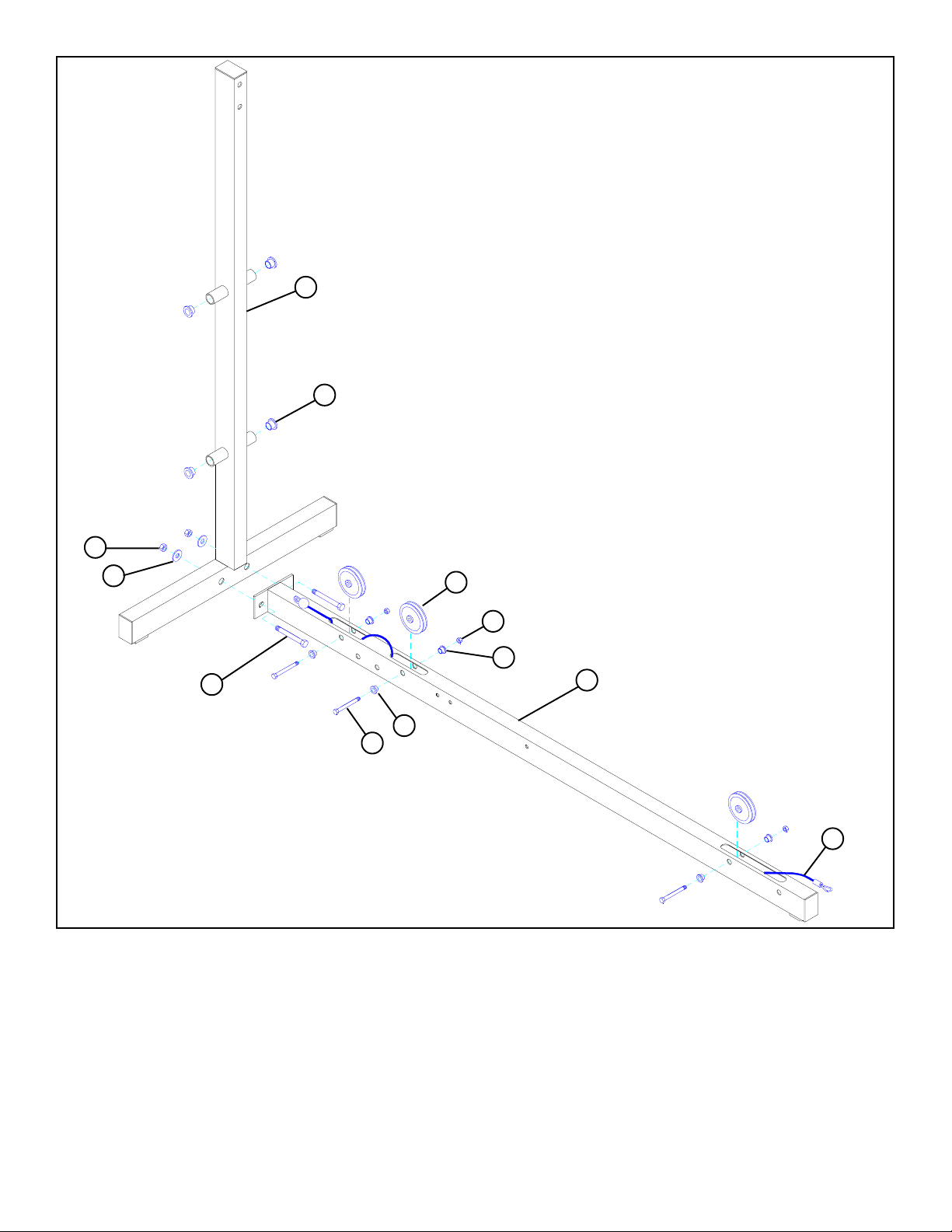
STEP 1
• Securely assemble REAR UPRIGHT (16 ) to BASE (10) using two 1/2 X 3" BOLTS (42), two 1/2" WASHERS (52), and two
1/2" LOCKNUTS (49).
• Slide 227" CABLE ASSEMBLY (90) through openings in BASE (10) as shown in FIGURE 1.
• Securely assembe three 3-1/2" PULLEYS (79) into BASE (10) using three 3/8 X 2-3/4" BOLTS (38), six 3/8" FLANGE
SPACERS (66), and three 3/8" LOCKNUTS (48). (NOTE: Make sure 227" CABLE ASSEMBLY (90) is routed under
PULLEYS and BOLTS.)
• Insert four 3/4" FLANGE BEARINGS (69) into tubes on REAR UPRIGHT (16) as shown in FIGURE 1
4
Page 5
3/8 X 3-3/4” 40
51
12
79
58
48
51
50 1/2” LOW HEIGHT
49
3
1/2 1/2 1/2 1/2
0
52
23
42 1/2 X 3”
1
86
2
34
FIGURE 2
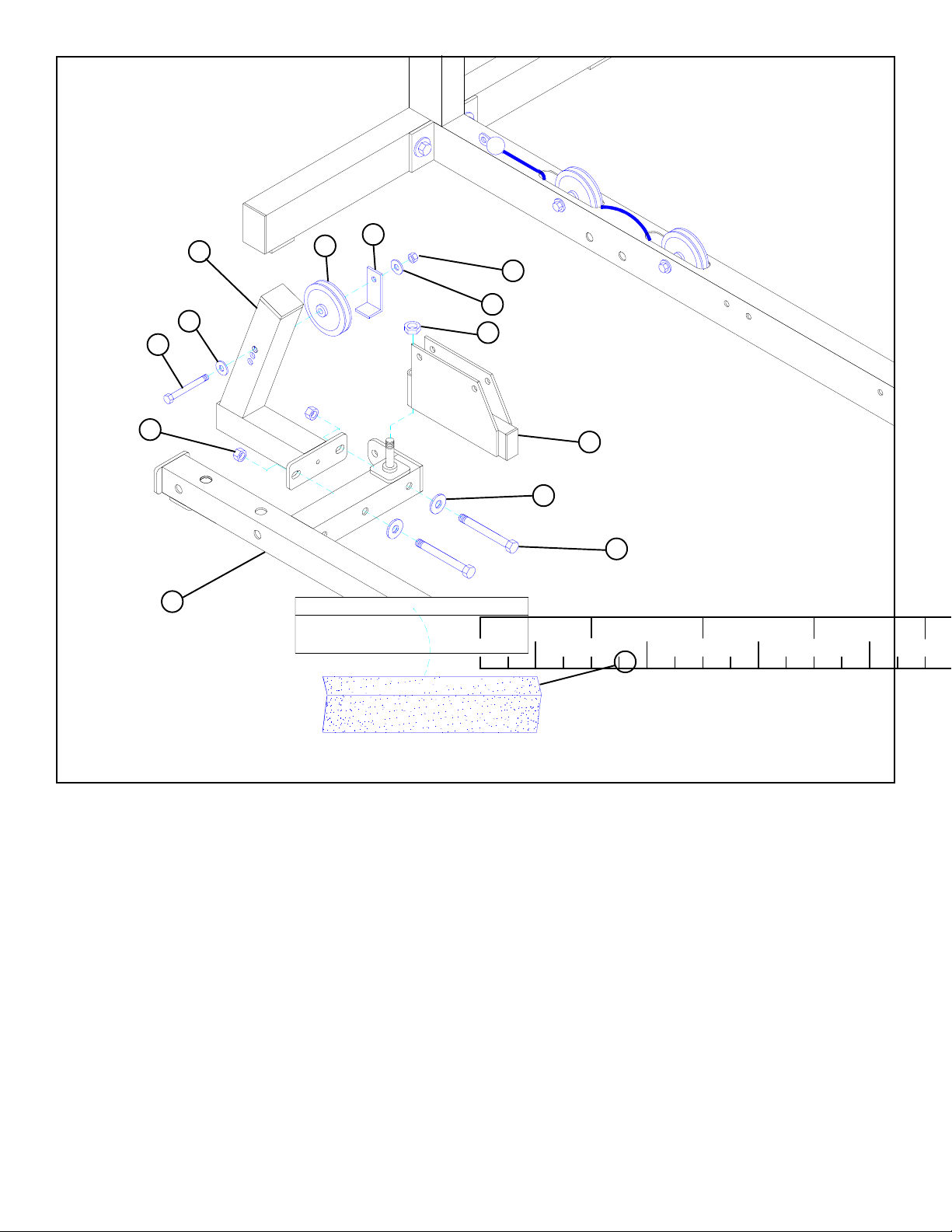
STEP 2
• Securely assemble one 3-1/2" PULLEY (79) to the top hole of the LEVER STOP (12) using one 3/8 X 3-3/4" BOLT (40), two 3/8"
WASHERS (51), one 2-3/8" RETAINING CLIP (58), and one 3/8" LOCKNUT (48). The extra holes in the LEVER STOP (12) are
to be used for cable adjustment.
• Securely attach LEVER STOP (12) to WEIGHT STACK BASE (3) using two 1/2 X 3" BOLTS (42), two 1/2" WASHERS (52),
and two 1/2" LOCKNUTS (49).
• Attach SWIVEL PULLEY BRACKET (23) to the WEIGHT STACK BASE (3) using one 1/2" LOW HEIGHT LOCKNUT
(50). (NOTE: Securely tighten, then back nut off 1/4 turn to allow the SWIVEL PULLEY BRACKET (23) to rotate freely.)
• Center 4 X 14" NON SKID STRIP (86) on WEIGHT STACK BASE (3) as shown in FIGURE 2.
5
Page 6
29
3/8 X 3-3/4” 40
49
16
51
9
79
48
51
58
42 1/2 X 3”
52
10
86
3
FIGURE 3
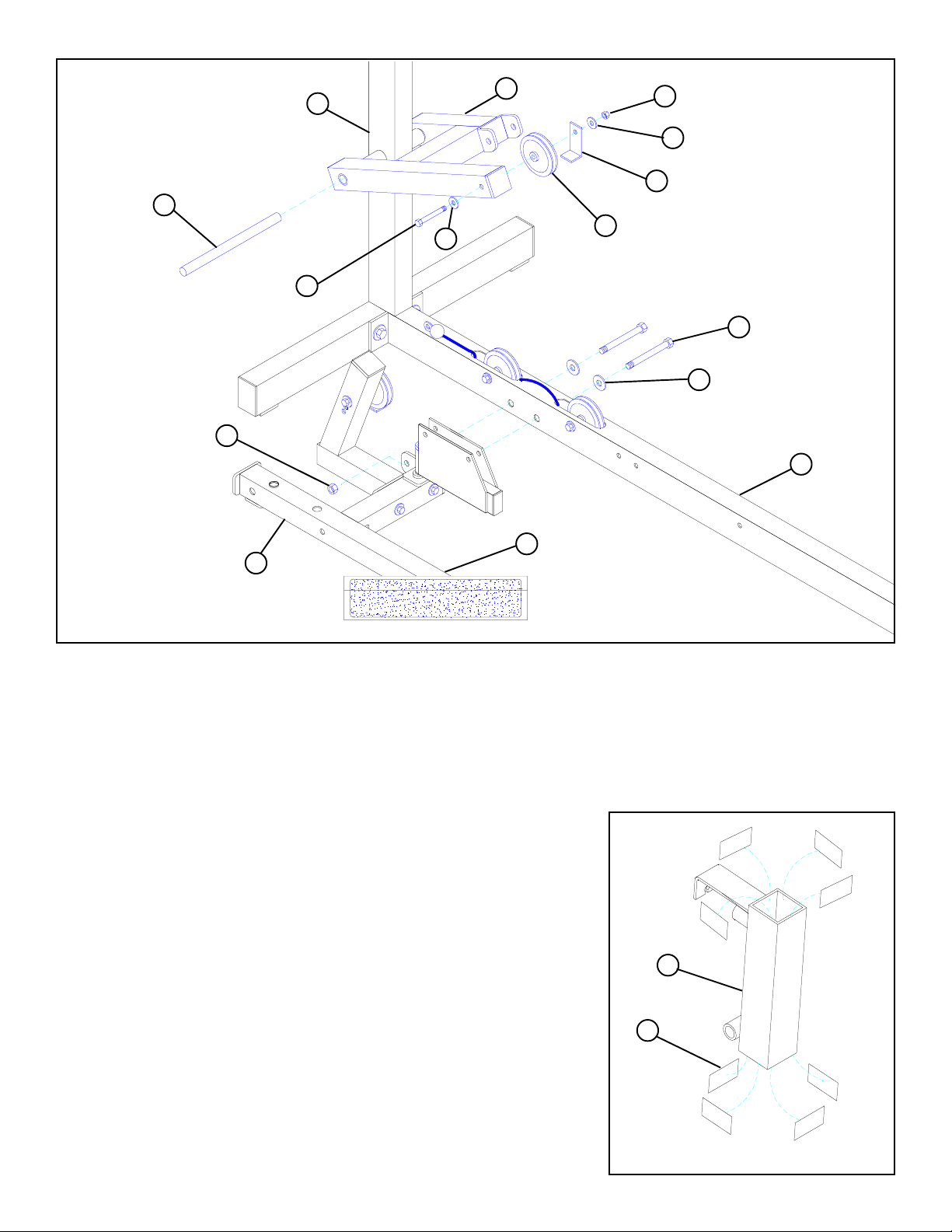
STEP 3
• Securely attach WEIGHT STACK BASE (3) to BASE (10) using two 1/2 X 3" BOLTS (42), two 1/2" WASHERS (52), and
one 1/2" LOCKNUT (49).
• Slide one 3/4 DIA X 11" SHAFT (29) through PRESS ARM LEVER (9) & tube on REAR UPRIGHT (16). See FIGURE 3.
• Securely assembe one 3-1/2" PULLEY (79) to PRESS ARM LEVER (9) using one 3/8 X 3-3/4" BOLT (40), two 3/8"
WASHERS (51), one 2-3/8" RETAINING CLIP (58), and one 3/8" LOCKNUT (48).
STEP 4
• Apply eight 1-3/4 x 3/4" PARAGLIDES (70) to the INSIDE of RECEIVING
TUBE (13) as shown in FIGURE 4. (NOTE: Throughly clean the inside
surface before attaching PARAGLIDES.)
13
70
FIGURE 4
6
Page 7
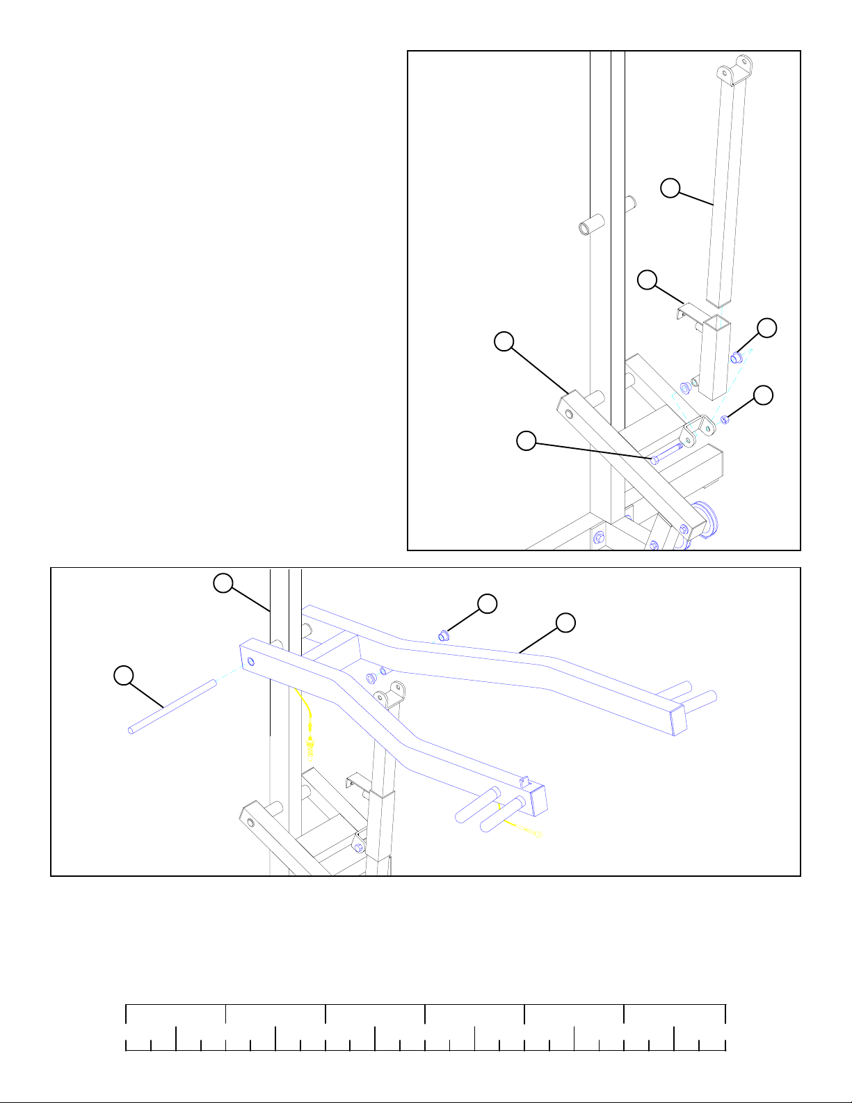
STEP 5
• Insert two 1/2" FLANGE BEARINGS (67) into
RECEIVING TUBE (13).
• Attach RECEIVING TUBE (13) to PRESS ARM LEVER
(9) using one 1/2 X 3-1/2" BOLT (43), and 1/2" LOW
HEIGHT LOCKNUT (50). (NOTE: Securely tighten,
then back nut off 1/4 turn to allow the RECEIVING
TUBE (13) to rotate freely.)
6
• Insert the ADJUSTMENT TUBE (6) into the
RECEIVING TUBE (13) as shown in FIGURE 5.
16
29
9
1/2 X 3-1/2” 43
FIGURE 5
67
13
67
50
1/2”
LOW
HEIGHT
8
FIGURE 6
STEP 6
• Slide one 3/4 DIA X 11" SHAFT (29) through PRESS ARM (8) & tube on REAR UPRIGHT (16). See FIGURE 6.
• Insert two 1/2" FLANGE BEARINGS (67) into PRESS ARM (8).
1/2 1/2 1/2 1/2 1/2 1/2
0
1
2
345
7
6
Page 8
8
43 1/2 X 3-1/2”
6
50
1/2” LOW
HEIGHT
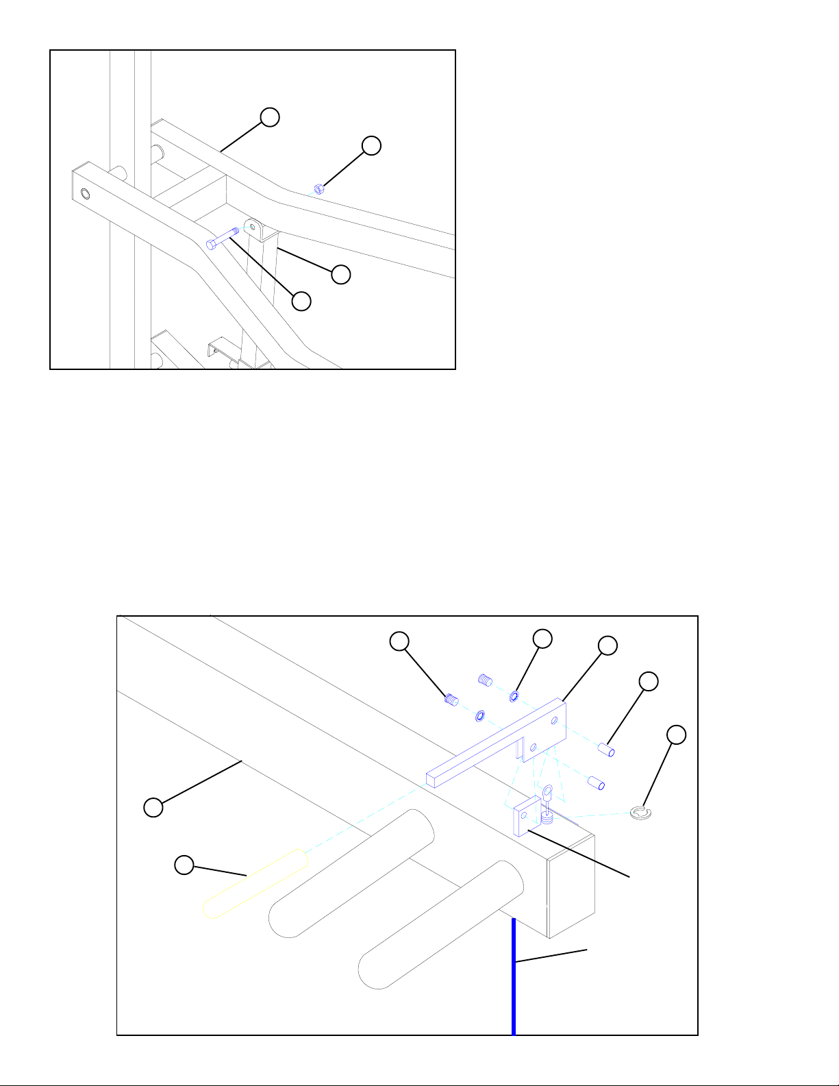
STEP 7
• Attach ADJUSTMENT SLIDE (6) to PRESS ARM
(8) using one 1/2 X 3-1/2" BOLT (43), and 1/2" LOW
HEIGHT LOCKNUT (50). (NOTE: Securely
tighten, then back nut off 1/4 turn to allow the
PRESS ARM (8) to rotate freely.)
FIGURE 7
STEP 8
• Insert the PUSH/PULL CABLE through the bottom of the PRESS ARM (8) up to the CONTROL LEVER (59) and hold in place
with one E-RING (62) as shown in FIGURE 8.
• Securely assemble the PUSH/PULL CABLE to the CONTROL LEVER (59) using one 3/8 IN. JOINT CONNECTOR CAP (61),
one #8 INT. TOOTH LOCK WASHER (63), and one 8-32 X 3/16 IN. SCREW (60) as shown in FIGURE 8.
• Slide one 4” VINYL SLEEVE (64) over the CONTROL LEVER (59). Then SECURELY assemble the CONTROL LEVER (59)
to the TAB on the PRESS ARM (8) using one 3/8” JOINT CONNECTOR CAP (61), one #8 INT. TOOTH LOCK WASHER
(63), and one 8-32 X 3/16 IN. SCREW (60) as shown in FIGURE 8.
60
8
64
63
59
61
62
TAB
FIGURE 8
PUSH/PULL
CABLE
8
Page 9
DETAIL 9
8
PUSH/PULL
CABLE
13
1/4” NUTS
DO NOT OVERTIGHTEN!
13
FIGURE 9
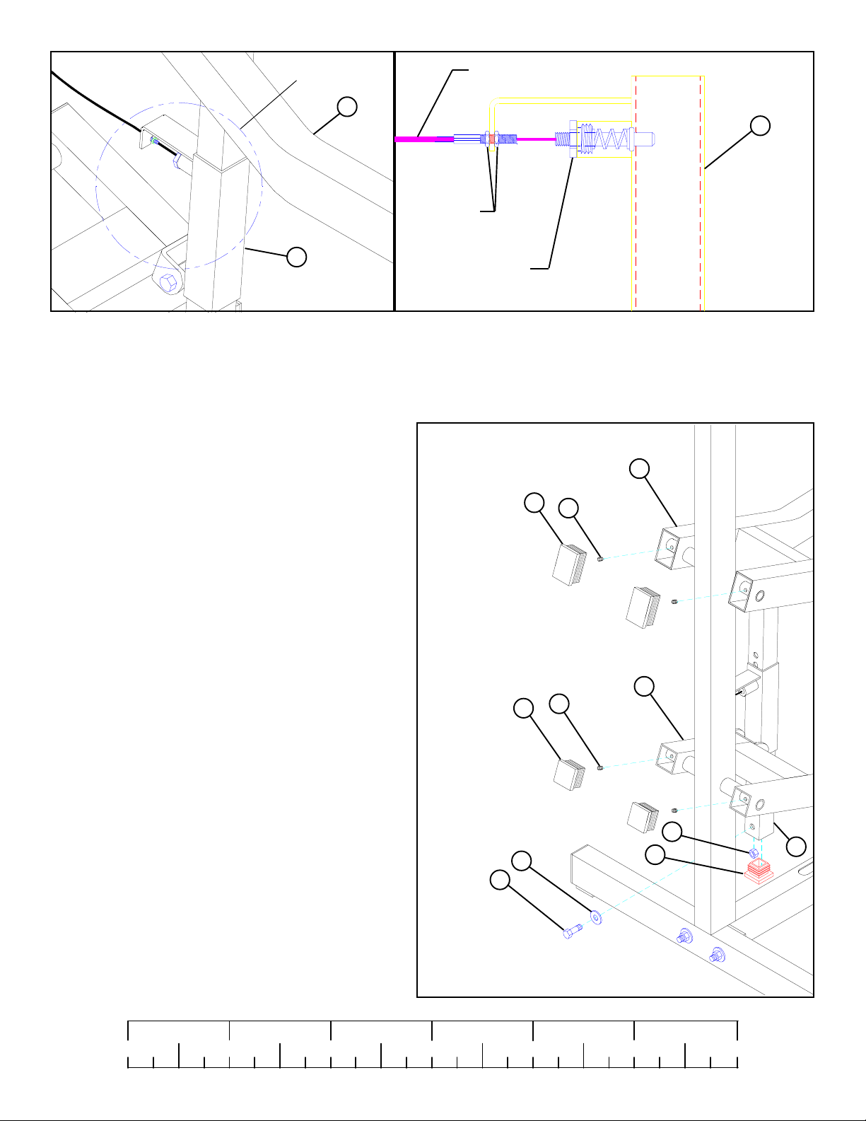
STEP 9
Assemble the PUSH/PULL CABLE from the PRESS ARM (8) to the SPRING PIN HOUSING and to the L-BRACKET on the
RECEIVING TUBE (13) as shown on FIGURE 9 and DETAIL 9 using the following steps:
· Thread the first 1/4-28 IN. NUT to the bottom of the threaded end of the CABLE. Allow the other 1/4-28 IN. NUT to hang loose
on the exposed CABLE until the SPRING PIN ASSEMBLY is attached.
· Securely assemble the SPRING PIN ASSEMBLY to the
SPRING PIN BARREL. (!!! IMPORTANT !!! TIGHTEN
THE NUT OF THE SPRING PIN ASSEMBLY SECURELY)
· Swing the PRESS ARM (8) up until the SPRING PIN of the
PUSH/PULL CABLE engages in one of the adjustment
holes.
· Thread the second 1/4-28 IN. NUT onto the threaded end of
the CABLE, and cinch the two 1/4-28 IN. NUTS around the
flat.
· Use the extra thread on the end of the CABLE to adjust out
slack. ( !!! DO NOT ADJUST OUT TO FAR !!! AL-
WAYS ALLOW SPRING PIN ASSEMBLY TO FULLY
ENGAGE)
STEP 10
SPRING PIN
ASSEMBLY
76
75
DETAIL 9
8
65
9
65
• Securely tighten two 5/32” SET SCREWS (65) and insert
two 3 X 2” END CAPS (75) into the open ends of PRESS
ARM (8) as shown in FIGURE 10.
• Securely tighten two 5/32" SET SCREWS (65) and insert
two 2” SQ. END CAPS (76) into the open ends of PRESS
ARM LEVER (9) as shown in FIGURE 10.
• Securely tighten one 3/8 X 1” BOLT (35), one 3/8” WASHER
(51), and one 3/8” LOCKNUT (48) to the bottom of ADJUSTMENT SLIDE (6) as shown in FIGURE 10.
• Insert one 1-3/4” SQ. END CAP (77) into the end of ADJUSTMENT SLIDE (6) as shown in FIGURE 10.
1/2 1/2 1/2 1/2 1/2 1/2
0
1
2
48
51
3/8 X 1” 35
77
FIGURE 10
345
9
6
6
Page 10
STEP 11
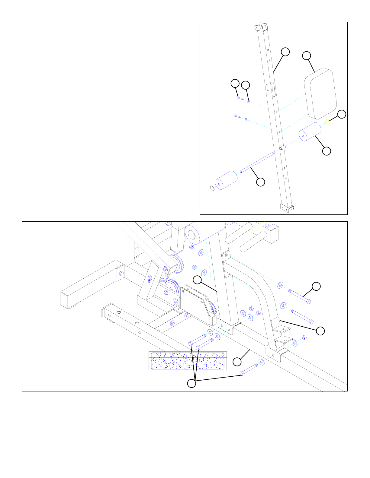
• Securely assemble the PEC SEAT PAD (27) to the FRONT UPRIGHT
(11) as shown, using two 3/8 X 4” BOLTS (41), and two 3/8” WASHERS (51) as shown in FIGURE 11.
• Assemble two ROLLER PADS (31) to the FRONT UPRIGHT (11)
using one 16” TUBE (34), and two STARLOCK COLLARS (75) as
shown in FIGURE 11.
3/8 X 4” 41
51
34
11
27
75
31
FIGURE 12
FIGURE 11
• All WASHERS & LOCKNUTS
are 3/8” WASHERS (51) & 3/8”
LOCKNUTS (48).
11
41 3/8 X 4”
1
10
3/8 X 3” 39
STEP 12
• Loosely attach FRONT UPRIGHT (11) to the BASE (10) using two 3/8 X 3” BOLTS (39), four 3/8” WASHERS (51), and two
3/8” LOCKNUTS (48) as shown in FIGURE 12. (NOTE: Make sure cable is routed under the bolts.)
• Loosely attach FRAME SUPPORT (1) to the BASE (10) using one 3/8 X 3” BOLT (39), two 3/8” WASHERS (51), and one 3/8”
LOCKNUT (48) as shown in FIGURE 12. (NOTE: Make sure cable is routed under the bolts.)
• Loosely attach FRAME SUPPORT (1) to the FRONT UPRIGHT (11) using two 3/8 X 4” BOLTS (41), four 3/8” WASHERS (51),
and two 3/8” LOCKNUTS (48) as shown in FIGURE 12.
10
Page 11
• All FLANGE SPACERS & LOCKNUTS
are 3/8” FLANGE SPACERS (66) & 3/8”
LOCKNUTS (48).
79
7
66
48
38 3/8 X 2-3/4”
92
FIGURE 13
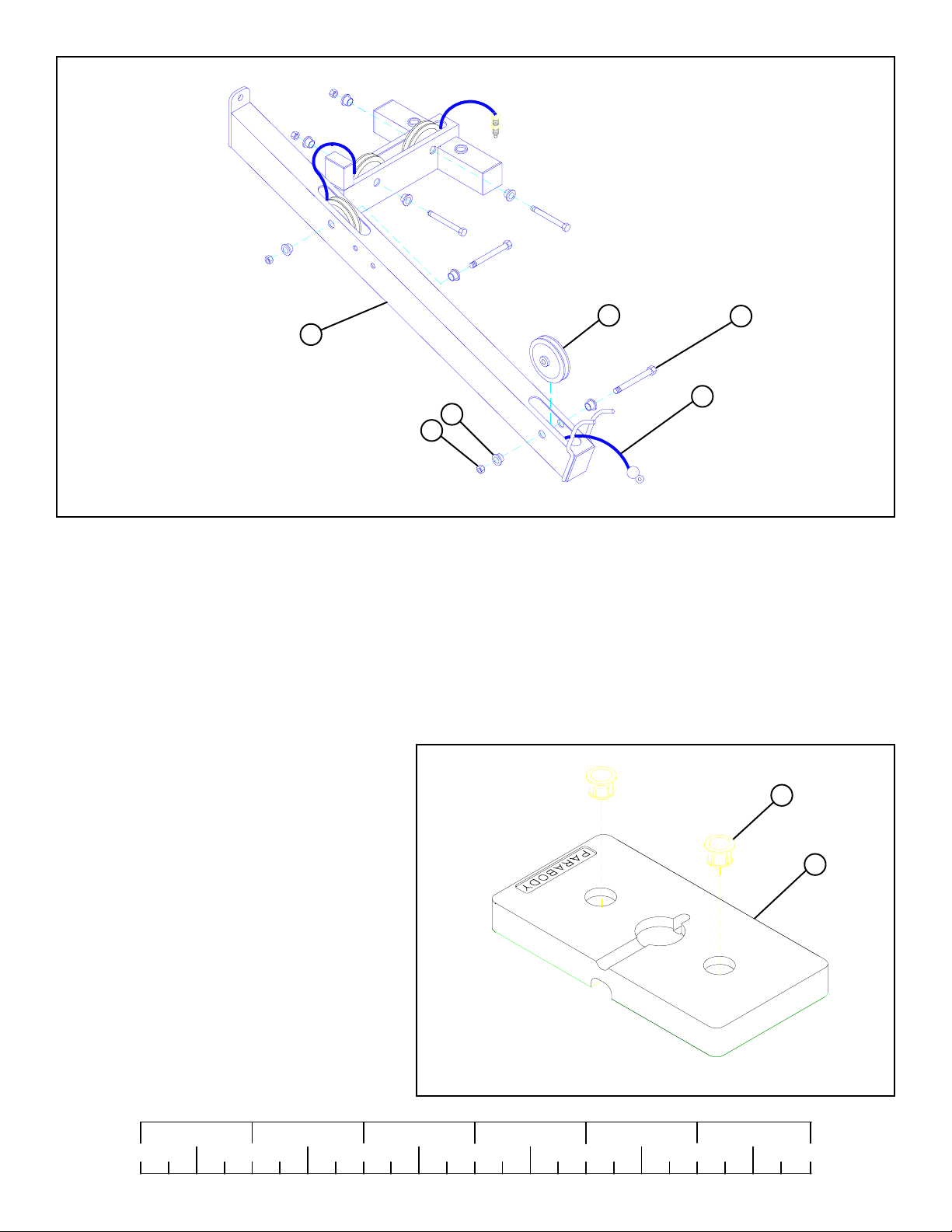
STEP 13
• Route the threaded end of LAT CABLE (92) through the TOP BOOM (7) as shown in FIGURE 13.
• Loosely assemble four 3-1/2” PULLEYS (79) to the slots in TOP BOOM (7) using four 3/8 X 2-3/4” BOLTS (38), eight 3/8”
FLANGE SPACERS (66), and four 3/8” LOCKNUTS (48) as shown in FIGURE 13. (NOTE: Make sure the cable is routed
under all the pulleys.)
STEP 14
• Snap two WEIGHT PLATE BUSHINGS (47) each,
into the PARABODY side of fifteen WEIGHT
PLATES (74) as shown in FIGURE 14.
1/2 1/2 1/2 1/2 1/2 1/2
0
1
2
FIGURE 14
345
11
47
74
6
Page 12
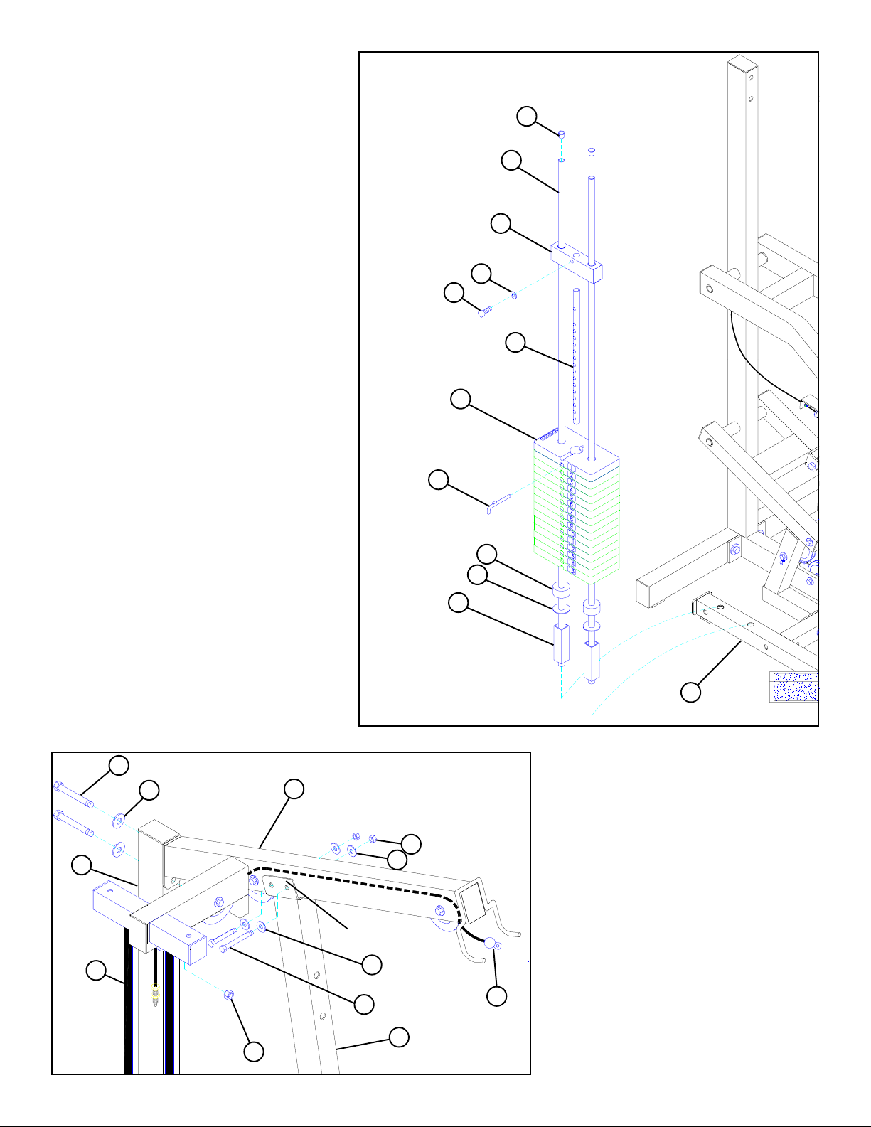
STEP 15
• Securely assemble the WEIGHT STACK SHAFT
(80) to the HEAD PLA TE (81) using one 3/8 X 1-1/
4” BOL T (46) and one 3/8” WASHER (51).
89
• Insert two GUIDE RODS (33) into the WEIGHT
STACK BASE (3) as shown on FIGURE 15.
(NOTE: Lubricate GUIDE RODS (33) with
silicon or teflon spray available at most hardware stores.)
• Slide two WEIGHT STACK SPACERS (34), two
3/4” WASHERS (53), and two WEIGHT STACK
CUSHIONS (88) - IN THAT ORDER - down
over the GUIDE RODS (33).
• Using EXTREME CARE slide all fifteen
WEIGHT PLATES (74) down over the GUIDE
RODS (33) on to the WEIGHT STACK CUSHIONS (88). Make sure that the keyholes of the
WEIGHT PLATES (74) are all facing the right
way.
• Slide the head plate assembly down over the
GUIDE RODS (33) onto the weight stack.
• Insert two CAP PLUGS (89) into the top ends of the
GUIDE RODS (33).
• Attach the WEIGHT STACK LABELS (94) to the
weight stack. Also insert the WEIGHT STACK
PIN (57) into the first WEIGHT PLATE (74) of
the weight stack.
33
81
51
3/8 X 1-1/4” 46
80
74
57
88
53
34
3
FIGURE 15
16
33
44 1/2 X 4”
52
49
7
Route LAT
CABLE over bolts
48
51
51
39 3/8 X 3”
11
FIGURE 16
12
STEP 16
• Swing the GUIDE RODS (33) under the TOP
BOOM (7) as shown on FIGURE 16.
• Loosely assemble the TOP BOOM (7) to the
REAR UPRIGHT (16) using two 1/2 X 4”
BOLTS (44), two 1/2” WASHERS (52), and
one 1/2” LOCKNUT (49).
• Loosely assemble the TOP BOOM (7) to the
FRONT UPRIGHT (11) using two 3/8 X 3”
92
BOLTS (39), four 3/8” WASHERS (51), and
two 3/8” LOCKNUTS (48). Make sure LAT
CABLE (92) is routed OVER top of bolts.
Page 13
TIGHTEN
16
7
TIGHTEN
11
TIGHTEN
FIGURE 17
STEP 17
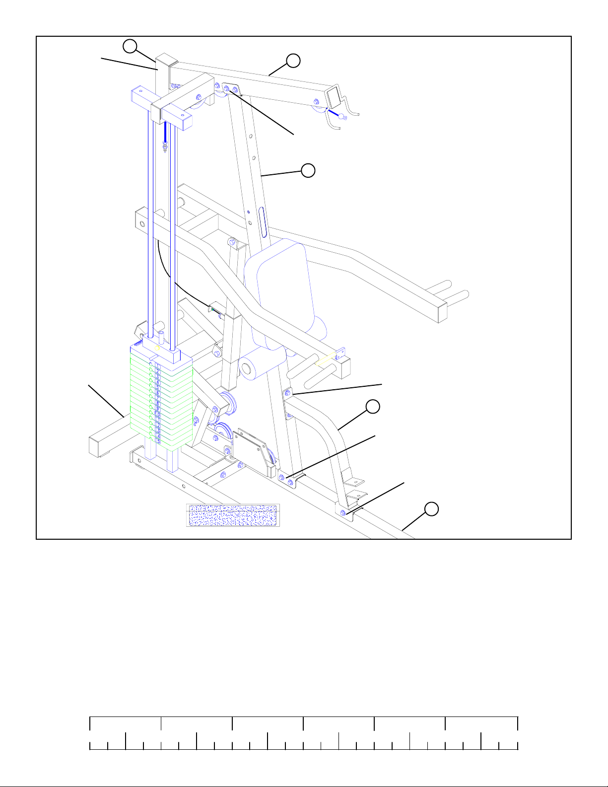
Securely tighten all loose frame connections made to this point.
Tighten the:
• REAR UPRIGHT (16) to the BASE (10).
• FRONT UPRIGHT (11) to the BASE (10).
• FRAME SUPPORT (1) to the BASE (10) and the FRONT UPRIGHT (11).
• TOP BOOM (7) to the REAR UPRIGHT (16).
TIGHTEN
1
TIGHTEN
TIGHTEN
10
• and the TOP BOOM (7) to the FRONT UPRIGHT (11).
1/2 1/2 1/2 1/2 1/2 1/2
0
1
2
345
13
6
Page 14
37 3/8 X 2”
51
21
51
58
79
FIGURE 18
48
STEP 18
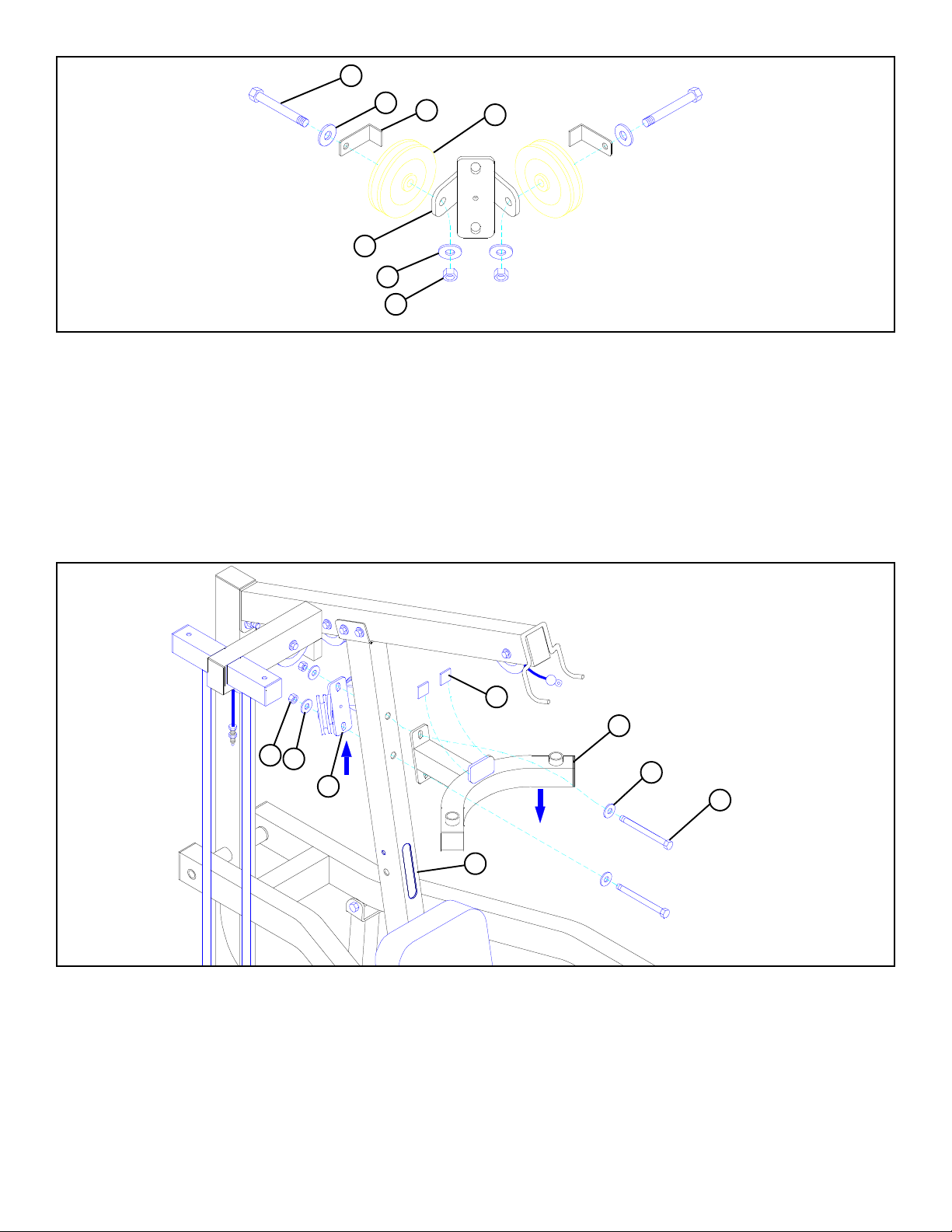
• Loosely assemble two 3-1/2” PULLEYS (79) and two 2-3/8” CABLE RETAINING CLIPS (58) to the CENTER PULLEY
BRACKET (21) using two 3/8 X 2” BOLTS (37), four 3/8” WASHERS (51), and two 3/8” LOCKNUTS (48). See FIGURE 18.
(NOTE: This connection will be tightened after the cable has been routed.)
87
17
49
52
21
11
52
45 1/2 X 4-1/2”
FIGURE 19
STEP 19
• Securely assemble the BEARING HOUSING (17) and the CENTER PULLEY BRACKEY (21) to the FRONT UPRIGHT (11) as
shown in FIGURE 19, using two 1/2 X 4-1/2” BOLTS (45), four 1/2” WASHERS (52), and two 1/2” LOCKNUTS (49). (NOTE:
The conntector plates on the BEARING HOUSING (17) and the CENTER PULLEY BRACKET (21) have slotted holes. Shift
the BEARING HOUSING (17) down as far as possible and the CENTER PULLEY BRACKET (21) up as far as possible
before tightening.)
• Attach two 1” X 1” GLIDES (87) to plate on the BEARING HOUSING (17) as shown.
14
Page 15
71
19
STEP 20
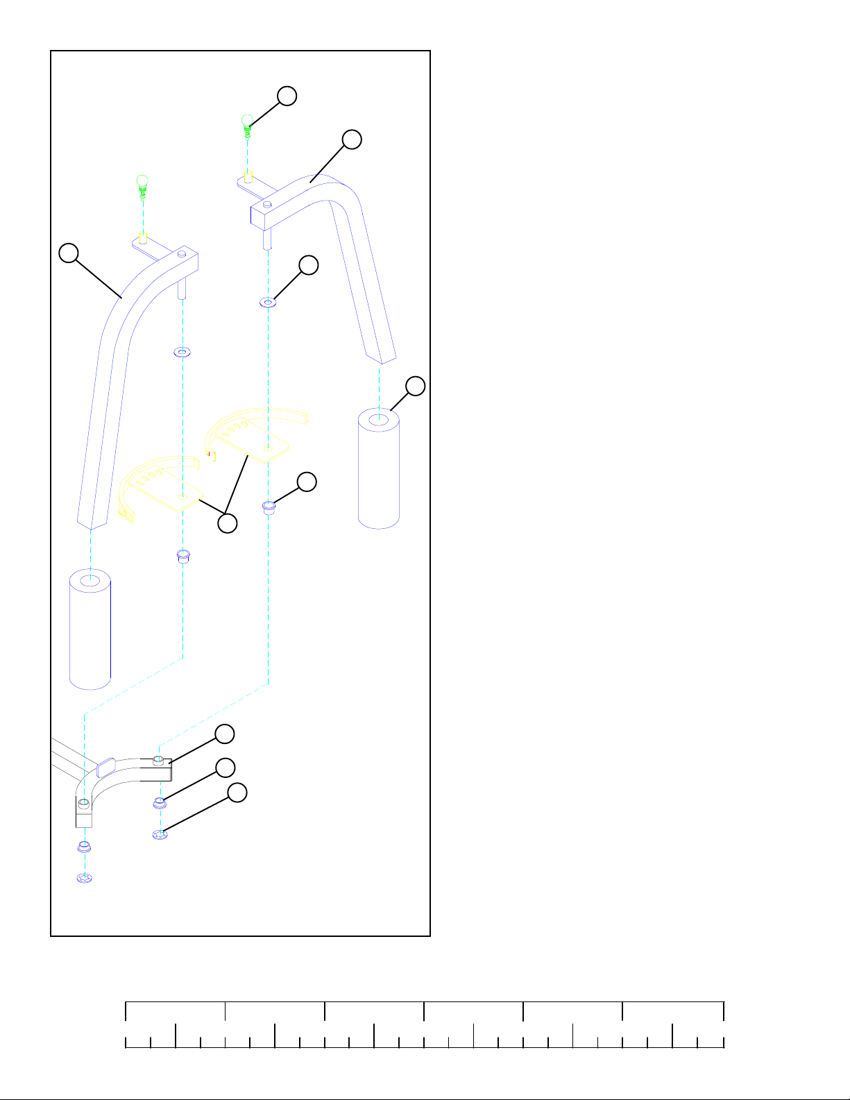
• Assemble two 3/4” THRUST WASHERS (68) and two PEC
CAMS (24) to the LEFT (20) & RIGHT (19) PEC ARMS, as
shown on FIGURE 20.
• Insert four 3/4” FLANGE BEARINGS (69) into the bushings
of the BEARING HOUSING (17).
20
24
68
• Insert the LEFT (20) & RIGHT (19) PEC ARMS through the
3/4” FLANGE BEARINGS (69) in the BEARING HOUSING
(17) on their respective side as shown, and secure them in place
with two 3/4” STARLOCK COLLARS (73).
32
• Slide two PEC DEC ROLLER PADS (32) onto the LEFT (20)
& RIGHT (19) PEC ARMS until the ROLLER PAD (32) is
flush with the bottom of the pec arms.
69
• (NOTE: If a lubricant is required coat the inside of the
ROLLER PAD (32) with rubbing alcohol or water. Also,
rotating the pad while pushing up will help ease assembly.)
• Securely assemble two 3/8” SPRING PIN ASSEMBLIES (71)
to the spring pin barrels of the PEC ARMS (19 & 20).
FIGURE 20
0
17
69
73
1/2 1/2 1/2 1/2 1/2 1/2
1
2
345
15
6
Page 16
1
55
2
95
71
54
15
FIGURE 21
STEP 21
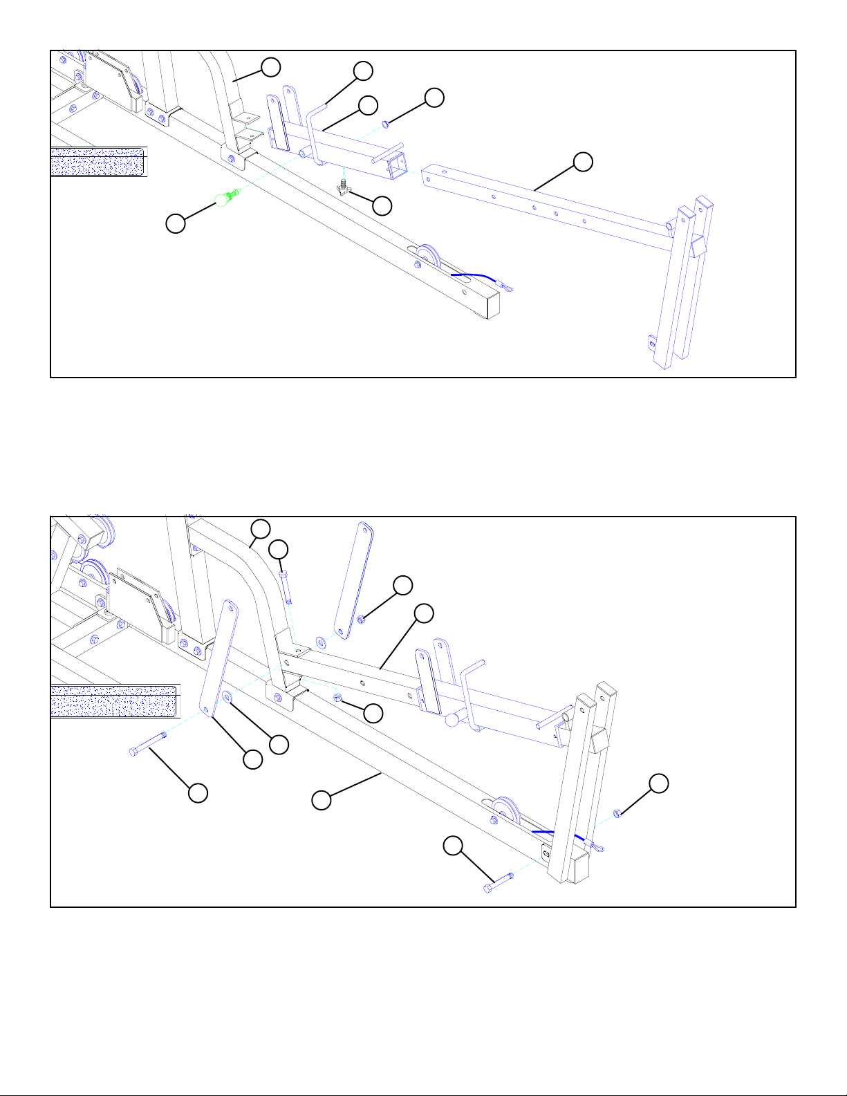
• Slide the 1/2” DIA U-PIN (55) through the bushing in the WOLFF SLEEVE (2) then force 1/2” PAL NUT (54) over end of 1/2” DIA
U-PIN (55).
• Slide the WOLFF SLEEVE (2) over the BENCH FRAME (15). (NOTE: Make sure the spring pin barrel is facing as shown in
FIGURE 21.)
• Slide the BENCH FRAME (15) between the angles on the FRAME SUPPORT (1).
• Securely assemb1e one 3/8” SPRING PIN ASSEMBLY (71) and one THUMBSCREW (95) to the WOLFF SLEEVE (2).
1
42 1/2 X 3”
50
15
49
52
18
1/2” LOW HEIGHT
43 1/2 X 3-1/2”
10
1/2 X 3” 42
50
FIGURE 22
STEP 22
• Securely fasten BENCH FRAME (15) to the BASE (10) using one 1/2 X 3” BOLT (42) and one 1/2” LOW HEIGHT LOCKNUT
(50).
• Securely attach BENCH FRAME (15) to the FRAME SUPPORT (1) using one 1/2” X 3” BOLT (42) and one 1/2” LOCKNUT (49).
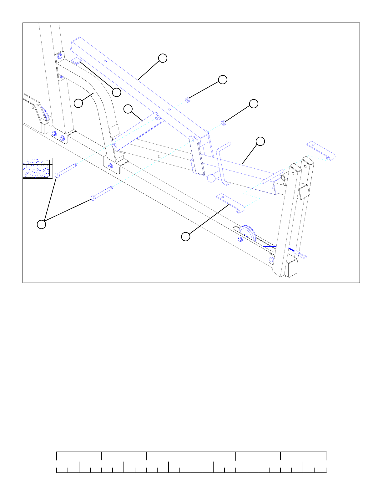
• Attach two 2 X 16-1/2” PLATES (18) to the BENCH FRAME (15) using one 1/2 X 3-1/2” BOLT (43), two 1/2” WASHERS (52),
and one 1/2” LOCKNUT (49). Make sure 1/2” WASHER (52) is on inside of plate as shown on FIGURE 22. (NOTE: Securely
tighten, then back nut off 1/4 turn to allow the 2 X 16-1/2” PLATES (18) to rotate freely.)
16
Page 17
85
14
49
43 1/2 X 3-1/2”
FIGURE 23
1
18
50 1/2” LOW HT .
2
78
STEP 23
• Attach WOLFF SLEEVE (2) to the BACK PAD SUPPORT (14) using one 1/2 X 3-1/2” BOLT (43) and one 1/2” LOW HEIGHT
LOCKNUT (50). (NOTE: Securely tighten, then back nut off 1/4 turn to allow the BACK PAD SUPPORT (14) to rotate
freely.) See FIGURE 23.
• Attach both 2 X 16-1/2” PLATES (18) to the bushing on the BACK PAD SUPPORT (14) using one 1/2 X 3-1/2” BOLT (43) and
one 1/2” LOCKNUT (49). (NOTE: Securely tighten, then back nut off 1/4 turn to allow the 2 X 16-1/2” PLATES (18) to rotate
freely.) See FIGURE 23.
• Slide one HINGE TAB (78) on each side of shaft on WOLFF SLEEVE (2). See FIGURE 23.
• Stick one 1-1/4” RUBBER BUMPER (85) on the BACK PAD SUPPORT (14) approximately 1/2” from the end of BACK PAD
SUPPORT (14).
1/2 1/2 1/2 1/2 1/2 1/2
0
1
2
345
6
17
Page 18
26
28
14
78
51
3/8 X 2-3/4” 38
51
35 3/8 X 1”
FIGURE 24
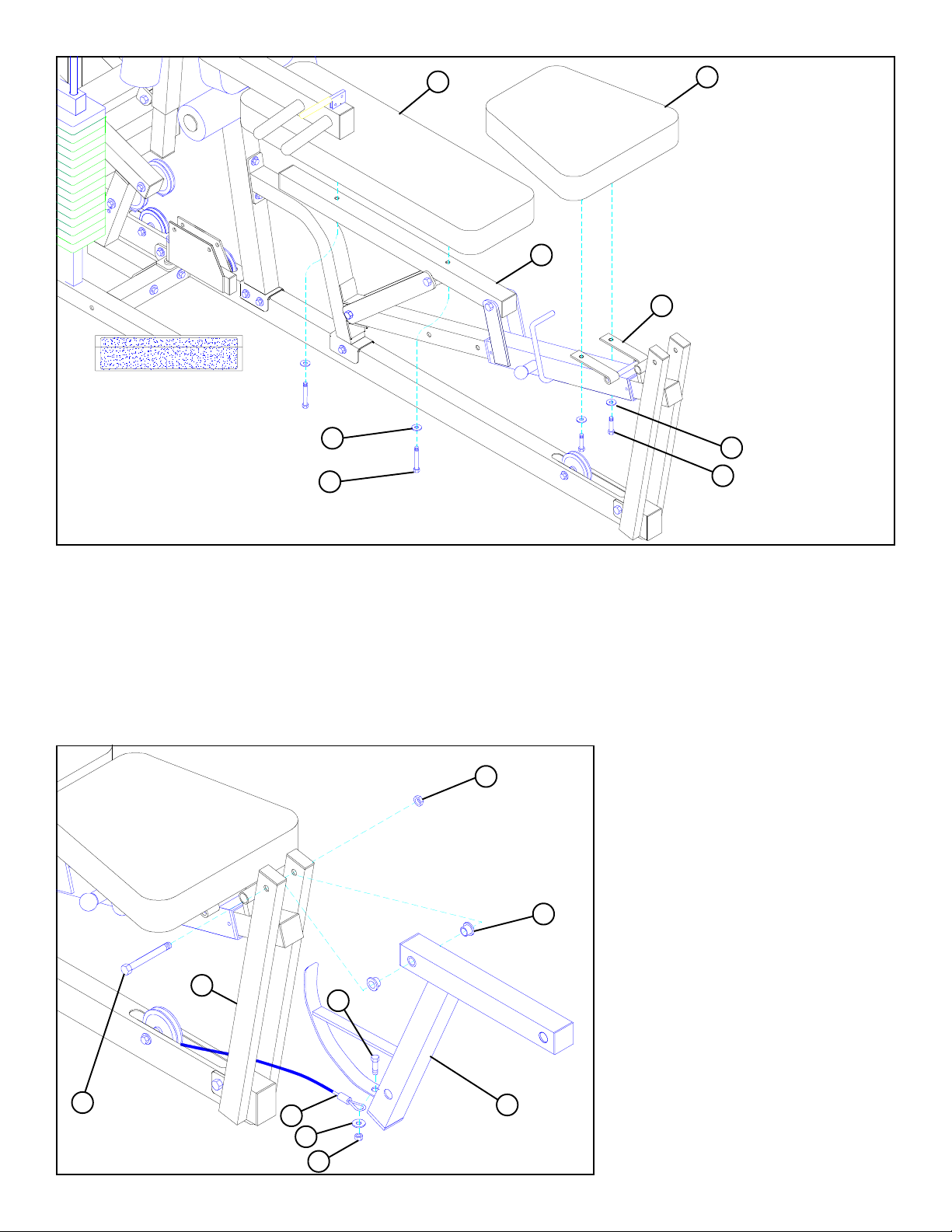
STEP 24
• Securely attach BACK SEAT PAD (26) to BACK PAD SUPPORT (14) using two 3/8 X 2-3/4” (38) and two 3/8” WASHERS (51).
• Securely attach LEG SEAT PAD (28) to HINGE TABS (78) using two 3/8 X 1” (35) and two 3/8” WASHERS (51) as shown in
FIGURE 24.
STEP 25
Assemble the LEG CURL/EXTENSION (4) to the BENCH FRAME (15) using the following steps:
50
1/2” LOW
HEIGHT
67
• Insert two 1/2” FLANGE BEARINGS (67)
into the LEG CURL/EXTENSION (4).
• Assemble the LEG CURL/EXTENSION (4)
to the BENCH FRAME (15) using one 1/2
X 4-1/2” (45) and one 1/2” LOW HEIGHT
LOCKNUT (50). (NOTE: Securely tighten,
then back nut off 1/4 turn to allow the LEG
CURL/EXTENSION (4) to rotate freely.)
45 1/2 X 4-1/2”
FIGURE 25
15
90
51
35 3/8 X 1”
4
48
18
• Securely fasten 227” CABLE (90) to the LEG
CURL/EXTENSION (4) using one 3/8 X 1”
BOLT (35), one 3/8” WASHER (51), and
one 3/8” LOCKNUT (48) as shown in FIGURE 25.
Page 19
31
4
34
73
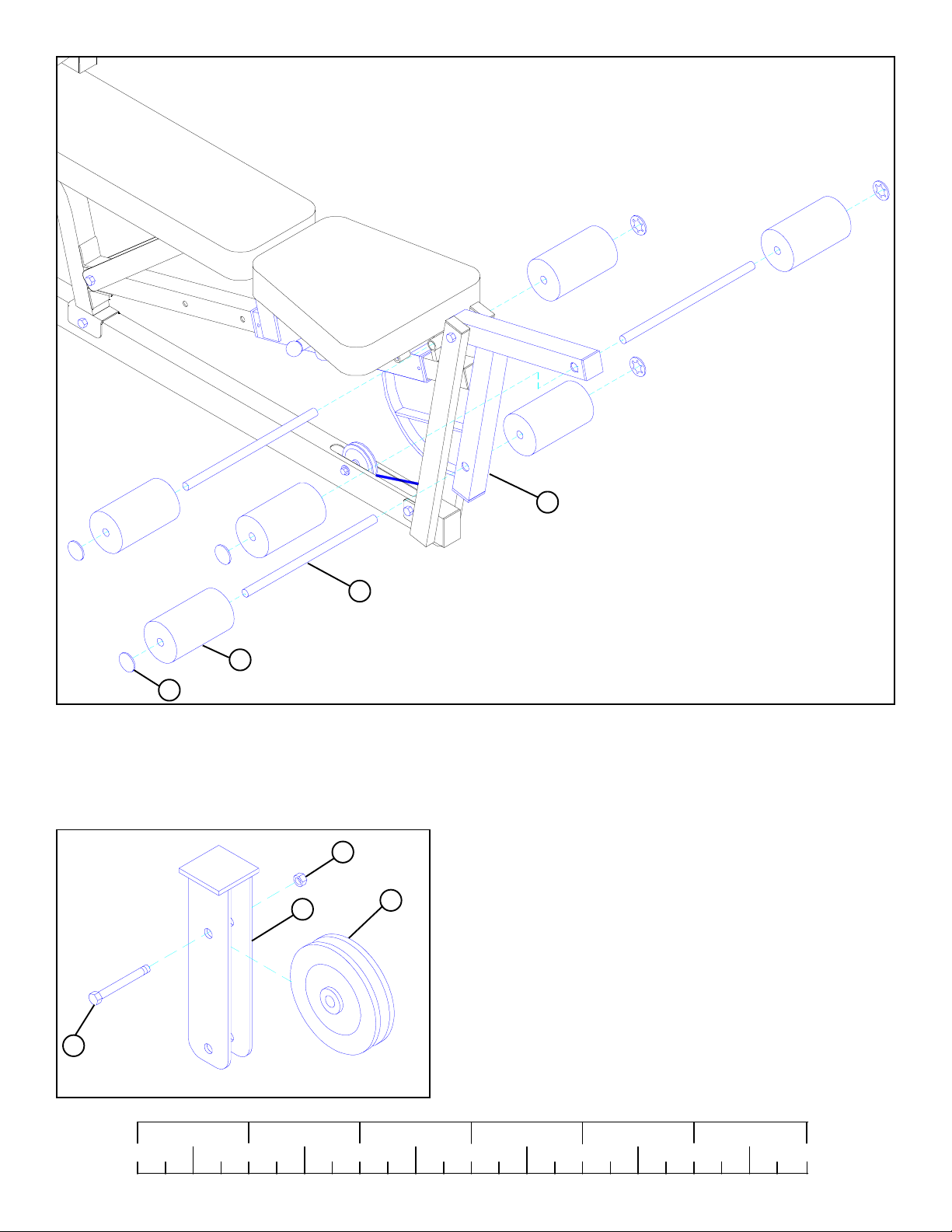
STEP 26
• Assemble four ROLLER PADS (31) to the LEG CURL/EXTENSION (4) as shown on FIGURE 26 using two 16” TUBES (34) and
four STARLOCK COLLARS (73).
• Assemble two ROLLER PAD (31) to the bushing on the BENCH FRAME (15) as shown on FIGURE 26 using one 16” TUBE (34)
and two STARLOCK COLLAR (73).
STEP 27
• Assemble one 3-1/2” PULLEY (79) to the FLOATING PULLEY
BRACKET (22) using one 3/8 X 1-3/4” BOLT (36) and one 3/8”
LOCKNUT (48) as shown in FIGURE 27.
36 3/8 X 1-3/4”
22
48
79
FIGURE 26
FIGURE 27
1/2 1/2 1/2 1/2 1/2 1/2
0
1
2
345
6
19
Page 20
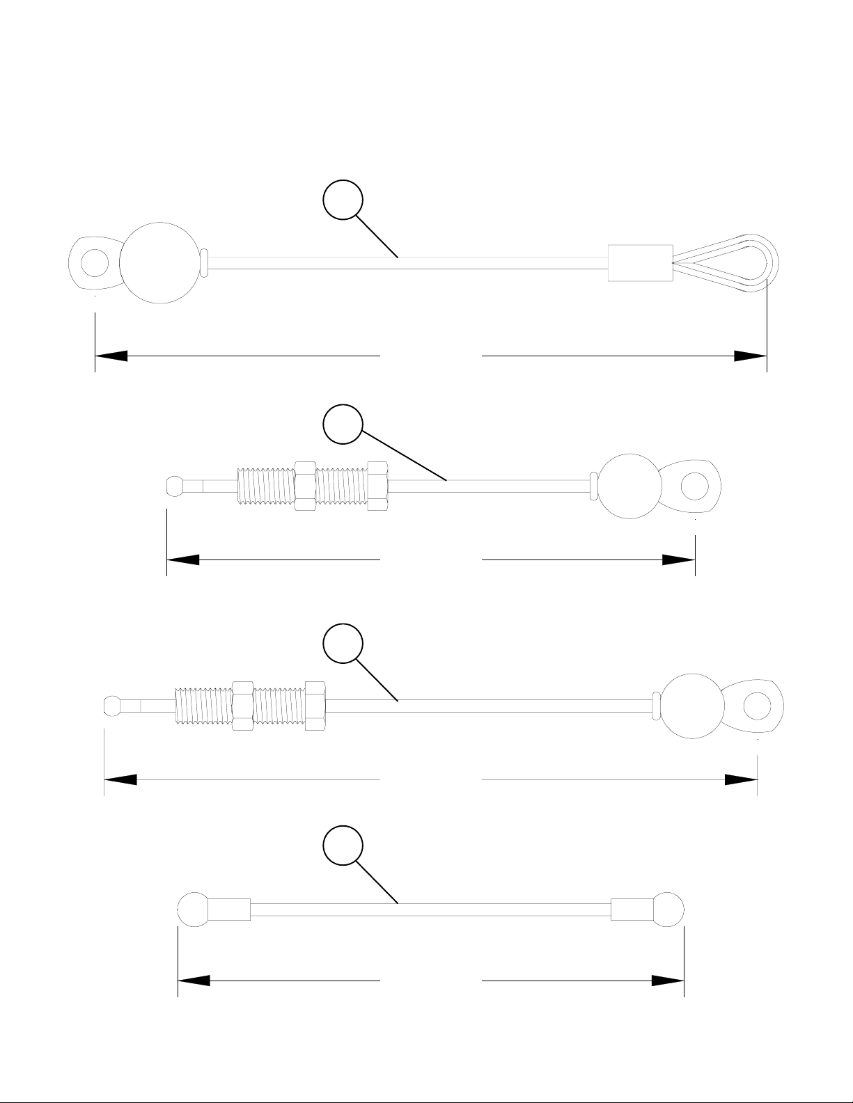
CABLE GUIDE
90LEG EXT. CABLE
228-1/2”
91AB CABLE
73”
92LAT CABLE
103-1/2”
93PEC DEC CABLE
77-5/8”
20
Page 21
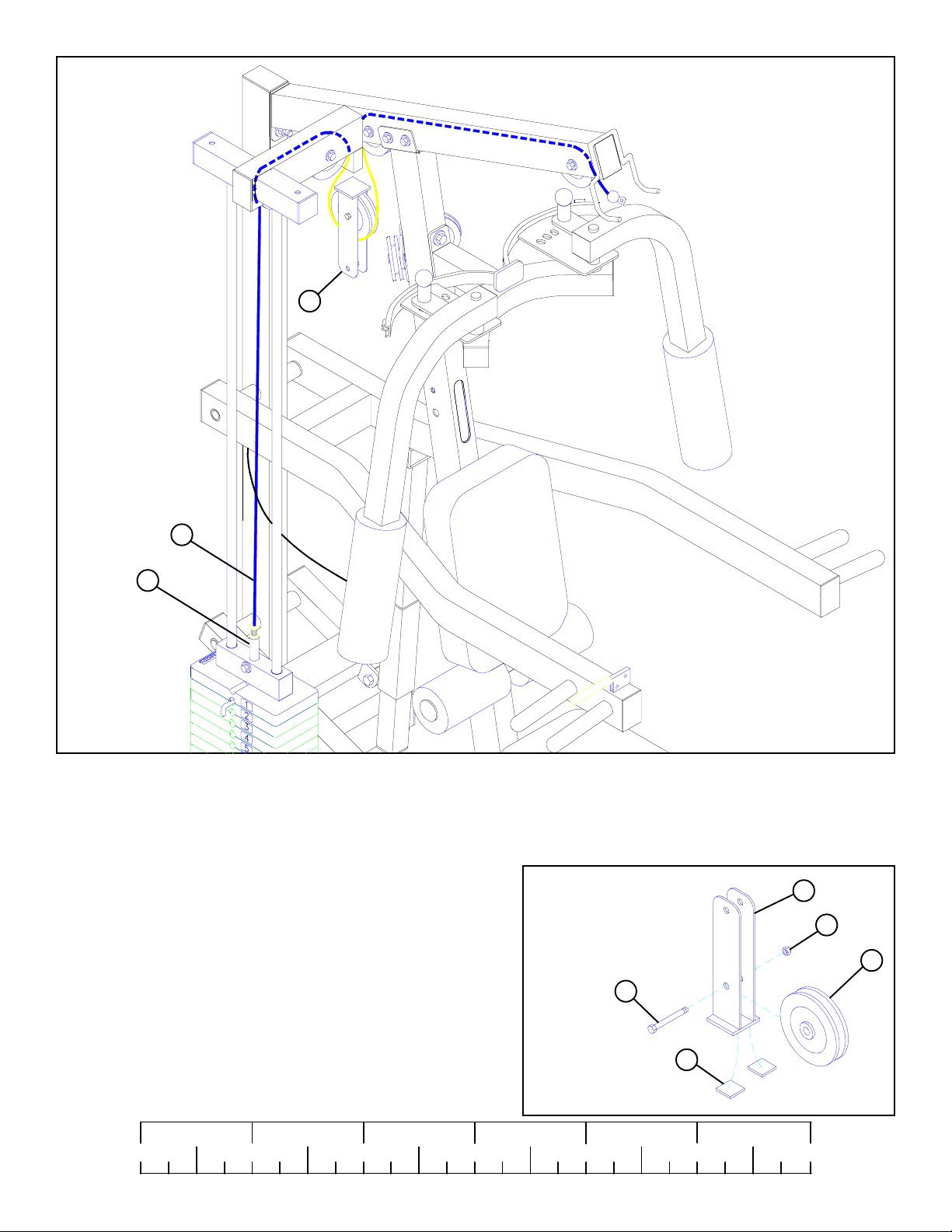
80
22
92
FIGURE 28
STEP 28
• Loop LAT CABLE (92) around pulley in FLOATING PULLEY BRACKET (22) as shown in FIGURE 27.
• Screw the threaded end of LA T CABLE (92) into the end of the WEIGHT ST ACK SHAFT (80) until the FLOA TING PULLEY BRACKET
(22) firmly contacts the end cap on the TOP BOOM (7) and the CABLE (92) slightly pulls on the HEAD PLA TE (81). Tighten the jam
nut securely. See FIGURE 28.
STEP 29
• Assemble one 3-1/2” PULLEY (79) to the other FLOATING PULLEY
BRACKET (22) using one 3/8 X 1-3/4” BOLT (36) and one 3/8” LOCKNUT (48) as shown in FIGURE 29.
3/8 X 1-3/4” 36
• Attach two 1” X 1” GLIDES (87) to the bottom of the second FLOATING PULLEY BRACKET (22) as shown.
87
22
48
79
FIGURE 29
1/2 1/2 1/2 1/2 1/2 1/2
0
1
2
345
21
6
Page 22
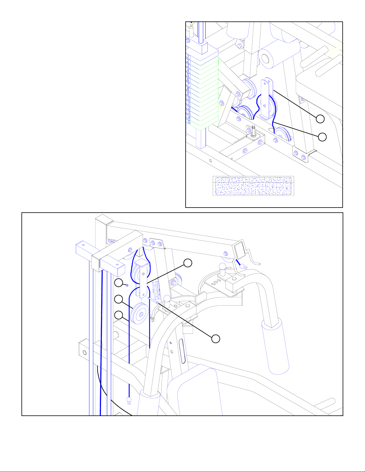
STEP 30
• Loop LEG EXT. CABLE (90), previously installed in BASE
(10), around pulley in lower FLOATING PULLEY BRACKET
(22) as shown in FIGURE 30.
22
90
48
79
90
FIGURE 30
22
36 3/8 X 1-3/4”
FIGURE 31
STEP 31
• Assemble one 3-1/2” PULLEY (79) around the LEG EXT. CABLE (90) and to the upper FLOATING PULLEY BRACKET (22)
using one 3/8 X 1-3/4” BOLT (36) and one 3/8” LOCKNUT (48) as shown in FIGURE 31.
22
Page 23
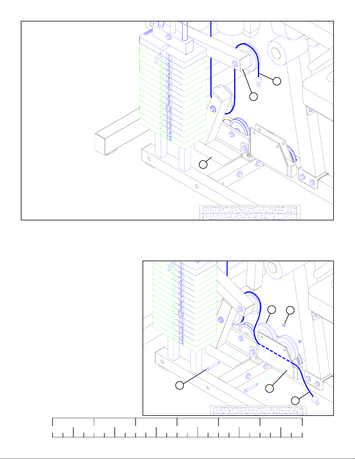
90
9
12
FIGURE 32
STEP 32
• Route ball end of LEG EXT. CABLE (90) under pulley and cable retaining clip on LEVER STOP (12) as shown in FIGURE 32.
(NOTE: The bolt holding pulley and cable retaining clip may need to be loosened to align cable retaining clip with cable.)
• Route ball end of LEG EXT. CABLE (90) under pulley and cable retaining clip on PRESS ARM LEVER (9). (NOTE: The bolt
holding pulley and cable retaining clip may need to be loosened to align cable retaining clip with cable.)
STEP 33
• After routing ball end of LEG EXT. CABLE
(90) through SWIVEL PULLEY BRACKET
(23), attach two 3-1/2” PULLEYS (79) using
two 3/8” X 2” BOLTS (37) and two 3/8” LOCKNUTS (48). See FIGURE 33.
1/2 1/2 1/2 1/2 1/2 1/2
0
1
2
3/8 X 2” 37
FIGURE 33
345
23
79
48
90
6
23
Page 24
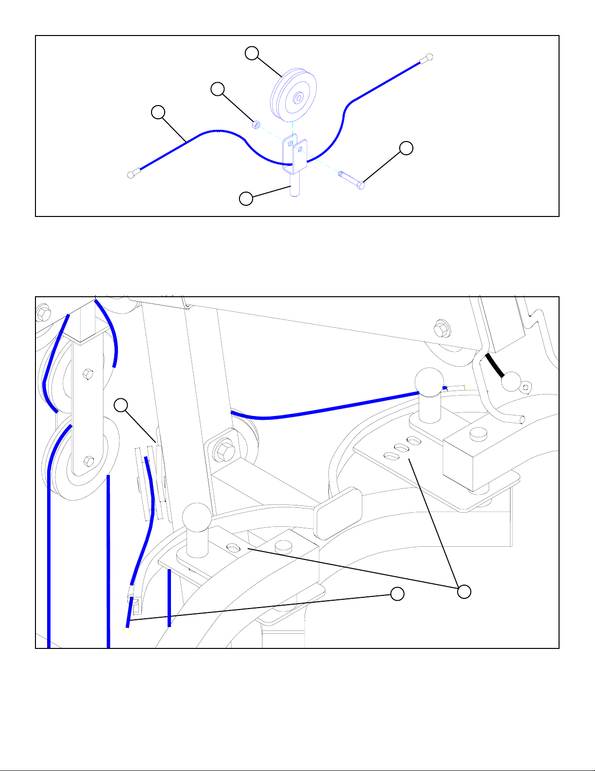
79
48
93
36 3/8 X 1-3/4”
5
FIGURE 34
STEP 34
• Assemble one 3-1/2” PULLEY (79) around the PEC DEC CABLE (93) and to the PULLEY BRACKET (5) using one 3/8 X 1-3/4”
BOLT (36) and one 3/8” LOCKNUT (48) as shown in FIGURE 34.
21
93
24
FIGURE 35
STEP 35
• Slide the ends of the PEC DEC CABLE (93) into the bushings on the PEC CAMS (24) as shown on FIGURE 35.
• Lay the PEC DEC CABLE (93) over the pulleys and under the cable retaining clips in the CENTER PULLEY BRACKET (21) as
shown in FIGURE 35. (NOTE: The bolt holding pulley and cable retaining clips may need to be loosened to align cable
retaining clips with cable.)
24
Page 25
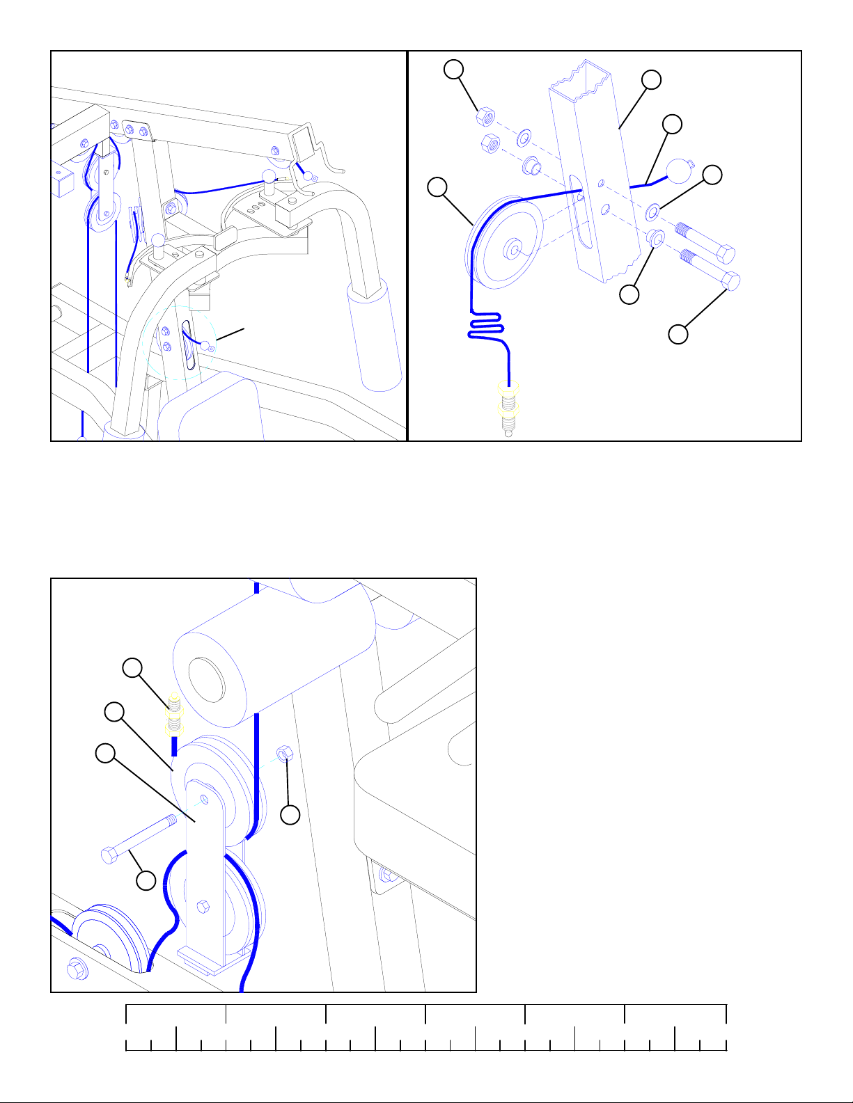
FIGURE 36
48
11
91
51
SEE DETAIL 36
79
66
3/8 X 2-3/4” 38
DETAIL 36
STEP 36
• Securely assemble the ball end of the AB CABLE (91) and one 3-1/2” PULLEY (79) to the FRONT UPRIGHT (11) using two 3/8
X 2-3/4” BOLTS (38), two 3/8” FLANGE SPACERS (66), two 3/8” WASHERS (51), and two 3/8” LOCKNUTS (48). (NOTE:
The AB CABLE (91) should be routed underneath the retaing bolt as shown in DETAIL 36.)
FIGURE 37
91
79
22
3/8 X 1-3/4” 36
STEP 37
• Route threaded end of AB CABLE (91) around 3-1/2”
PULLEY (79) while assembling one 3-1/2” PULLEY (79) to the lower FLOATING PULLEY
BRACKET (22) using one 3/8 X 1-3/4” BOLT (36)
and one 3/8” LOCKNUT (48) as shown in FIGURE
37.
48
1/2 1/2 1/2 1/2 1/2 1/2
0
1
2
345
25
6
Page 26
93
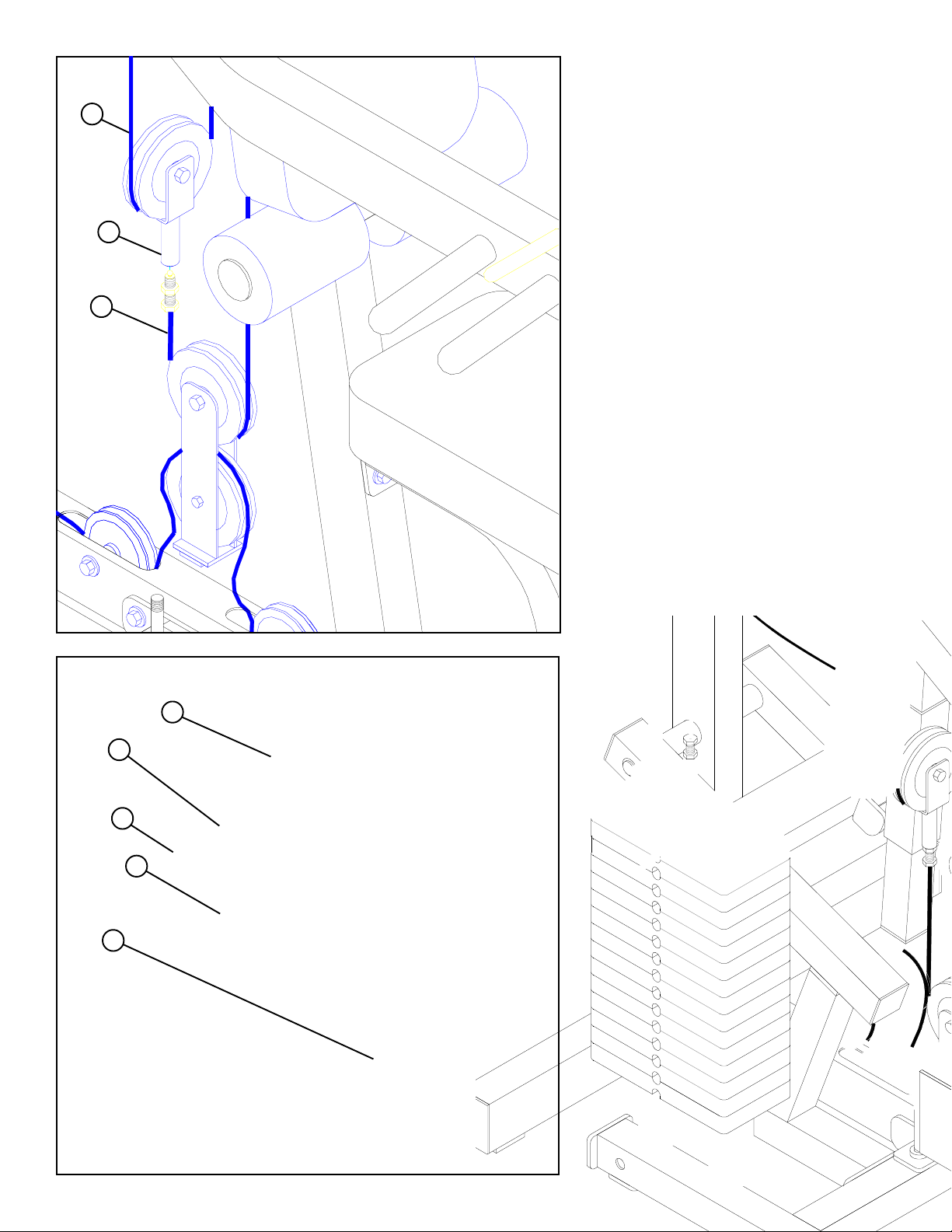
STEP 38
• Screw the threaded end of AB CABLE (91) approximately 3/4” into the end of the PULLEY
BRACKET (5) and tighten jam nut securely as
shown in FIGURE 38.
• IMPORTANT! Make sure the cables are running
in the grooves of all pulleys.
5
91
12
81
74
57
92
FIGURE
38
CABLE ADJUSTMENT
For maximum performance, the HEAD PLA TE
should should just barely sit on the top WEIGHT
PLA TE and the UPPER FLOA TING PULLEY
BRACKET should firmly contact the PLA TE on the
TOP BOOM, and the LOWER FLOATING PULLEY
BRACKET should firmly contact the BASE.
• The following adjustments can be made to adjust
the cable tension:
• If upon completion of assembly, the HEAD
PLATE (81) does not sit on top of the first
WEIGHT PLATE (74), push the HEAD PLATE
(81) down, insert the WEIGHT STACK PIN (57)
and perform several repetitions at the press station. This will relax the cable system and prevent
the HEAD PLATE (81) from lifting up.
• If after completing previous step, the HEAD
PLATE (81) still does not sit on top of the first
WEIGHT PLATE (74) or if there is excess slack
in the cable system, adjust the threaded end of the
LAT CABLE (92) accordingly and retighten the
jam nut.
26
• If there is excess slack in the LEG CABLE, move
the PULLEY attached to the LEVER STOP (12)
down one hole.
• If there is excess slack in the AB or PEC DEC
cable system, adjust the threaded end of the AB
CABLE (91) accordingly and retighten the jam
nut.
• IMPORTANT! Retighten both jam nuts when
adjustment is completed.
Page 27
72
25
72
82
56
72
83
FIGURE 40
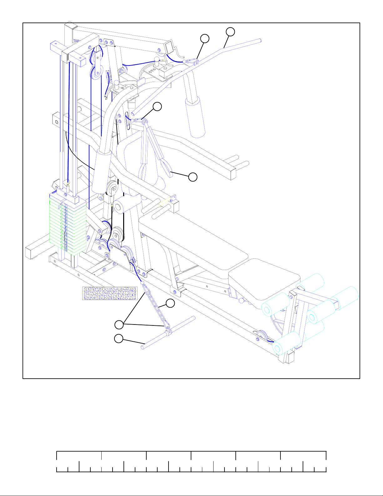
STEP 40
• Attach the LAT BAR (25) to the ball end of cable using one 5/16” SNAP LINK (72).
• Attach the AB CRUNCH STRAP (82) to the ball end of cable using one 5/16” SNAP LINK (72).
• Attach the LOW ROW BAR to the ball end of cable using two 5/16” SNAP LINKS (72) and one CHAIN (56).
Thank you for purchasing the Parabody 400101 Home Gym. If unsure of proper use of equipment, call
your local Parabody distributor or call the Parabody customer service department at (800) 328-9714.
1/2 1/2 1/2 1/2 1/2 1/2
0
1
2
345
27
6
 Loading...