

Page 1
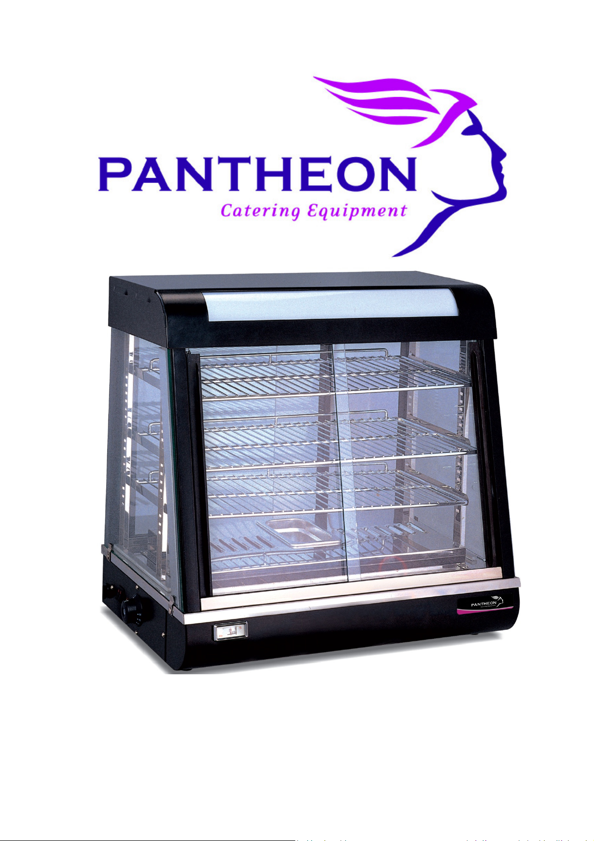
Heated Display Cabinet
HDC1, HDC2 and HDC3 Operating Manual
Page 2
Introduction
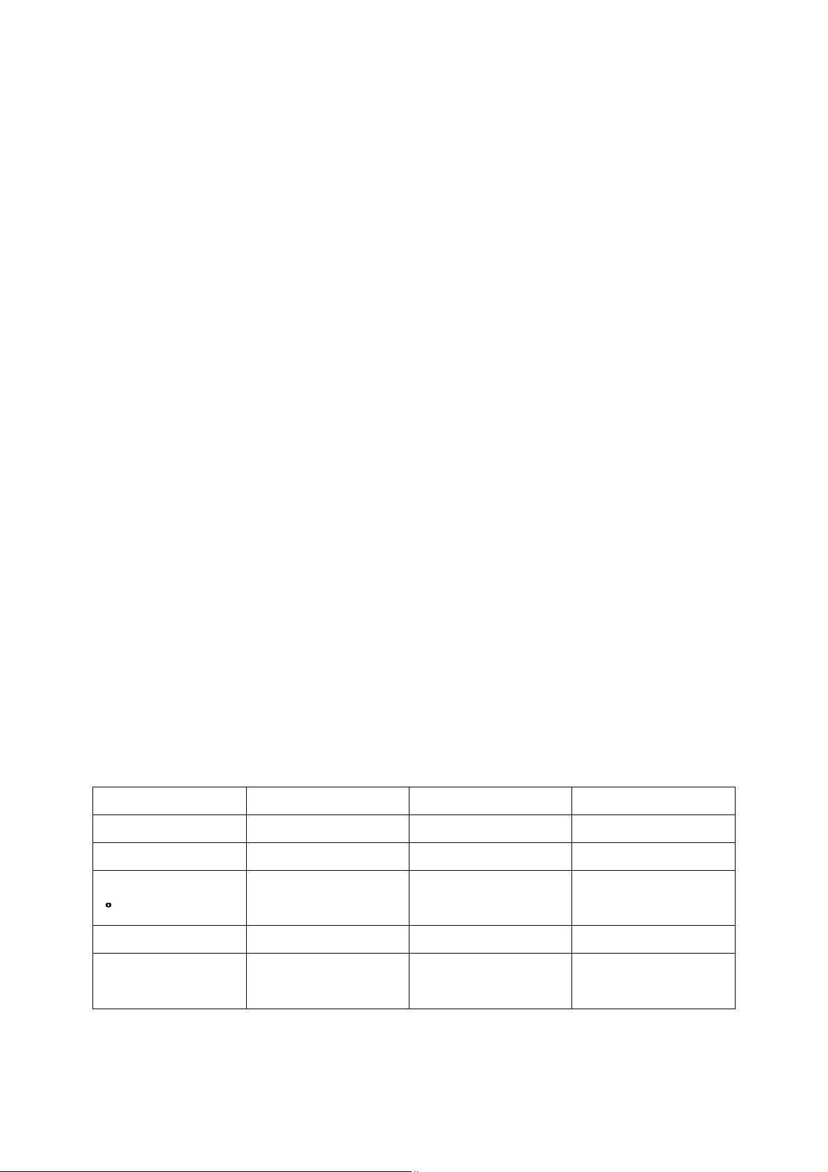
Model:
HDC1
HDC2
HDC3
Voltage (V)
220
-
240V 50Hz
220
-
240V 50Hz
220
-
240V
50Hz
Power (W)
1840
1840
2200
Temp. Range
C)
C)C)
C)
30-90 30-90 30-90
Weight (Kg)
37 50 72
Dimensions
660w x 437d x
900w x 480d x
1200w x 480d x
Thank you for purchasing a Pantheon Catering Equipment product. In this
booklet you will find instructions for safe operation so please read carefully
and retain for future reference.
Warnings and Precautions
The following warnings and precautions are important and must be observed:
• Ensure voltage and frequency power requirements for the heated
display cabinet match that of the supply.
• The machine must be earthed when used. There is a danger of electric
shock if it is not earthed.
• In case of emergency, please turn off the power switch and unplug the
machine.
• If the electric wire becomes damaged, a qualified engineer or the
manufacturer must replace it.
Pantheon Catering Equipment is not responsible for any accidents or faults
caused by amendments made to the machine or improper use by the user.
Technical Data
Specifications:
(
(mm)
635h
590h
810h
Page 3

Installation
Place the device on top of a solid, even, safe and stable surface that tolerates
the weight of the unit.
Position the device appropriately so that the plug is always accessible.
When you receive the product, the glass sliding doors are packed separately
inside the chamber. Be sure to remove these first and following the
instructions below to fit them correctly:
Glass sliding Doors:
The unit has front and rear sliding doors. When unpacking, note that the
longer doors fit at the front / slopped section.
The doors are fitted by placing the door into the channel in the top section of
the unit first; pushing the glass upwards, just enough to enable the bottom of
the door to clear the bottom channel and drop down into position.
There are two channels which allow the glass doors to slide past one another.
Ensure that the handles are towards the outside of the unit.
Fit the rear doors in the same manner. There are two plastic blocks supplied,
which if placed in the bottom channels in front of the glass, this will prevent
the doors from opening.
Shelving system:
There are four upright channels which locate into slots provided inside the
unit.
The channels have a flat tab at each end; the top side is slightly longer.
Place the channel vertically into the slot provided in the top of the unit and
then drop down to fit through the corresponding slot in the bottom.
Ensure that flat sides are facing inside the unit.
The shelf support angles fit into the slots in the upright channel. They can be
positioned level or slopping forward according to preference.
Page 4

The wire shelf is positioned on top of the support angle and fits against the
securing tab at the rear of the support angle which prevents the shelf from
sliding forward.
Operating Instructions
1. Before first use, clean the inside chamber and the tray grids with a damp
cloth.
2. After cleaning, dry the unit thoroughly before use.
3. Take out the water pan inside the chamber and fill it sufficiently. The
water pan is in place to produce moisture to keep the inside
environment warm throughout.
4. Connect the unit to a suitable power supply.
5. Rotate the thermostat clockwise to your required temperature, the
yellow heating light will illuminate.
6. The inside temperature of the unit is clearly displayed on the
temperature display on the front of the unit.
7. There is also a light switch, which is optional, to illuminate the content of
the heated display cabinet.
8. It is advised to that the water level in the water pan is checked on a daily
basis, to ensure the unit continues to function correctly.
Maintenance
Cleaning:
It is advised that the unit should be cleaned on a weekly basis to prolong its life
and ensure it continues to run correctly. Prior to cleaning ensure the device is
switched off and unplugged from the mains. Also, allow sufficient time for the
unit to cool if cleaning the cabinet shortly after use.
A damp cloth can be used to wipe down the control panel, surface of the
device and power cord.
Page 5
Be careful not to let water into the components of the unit, as it may cause the
unit to malfunction.
All parts must be dried thoroughly before reusing the unit.
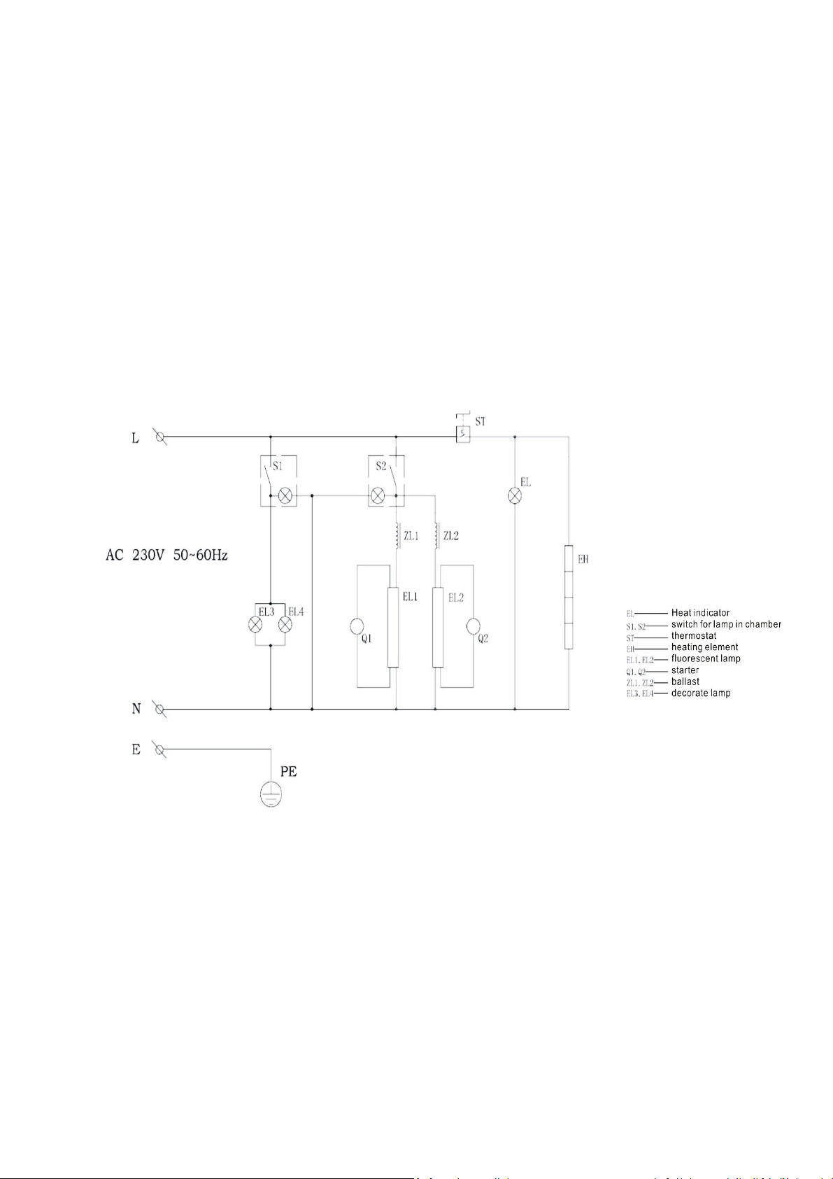
Circuit Diagram
Page 6
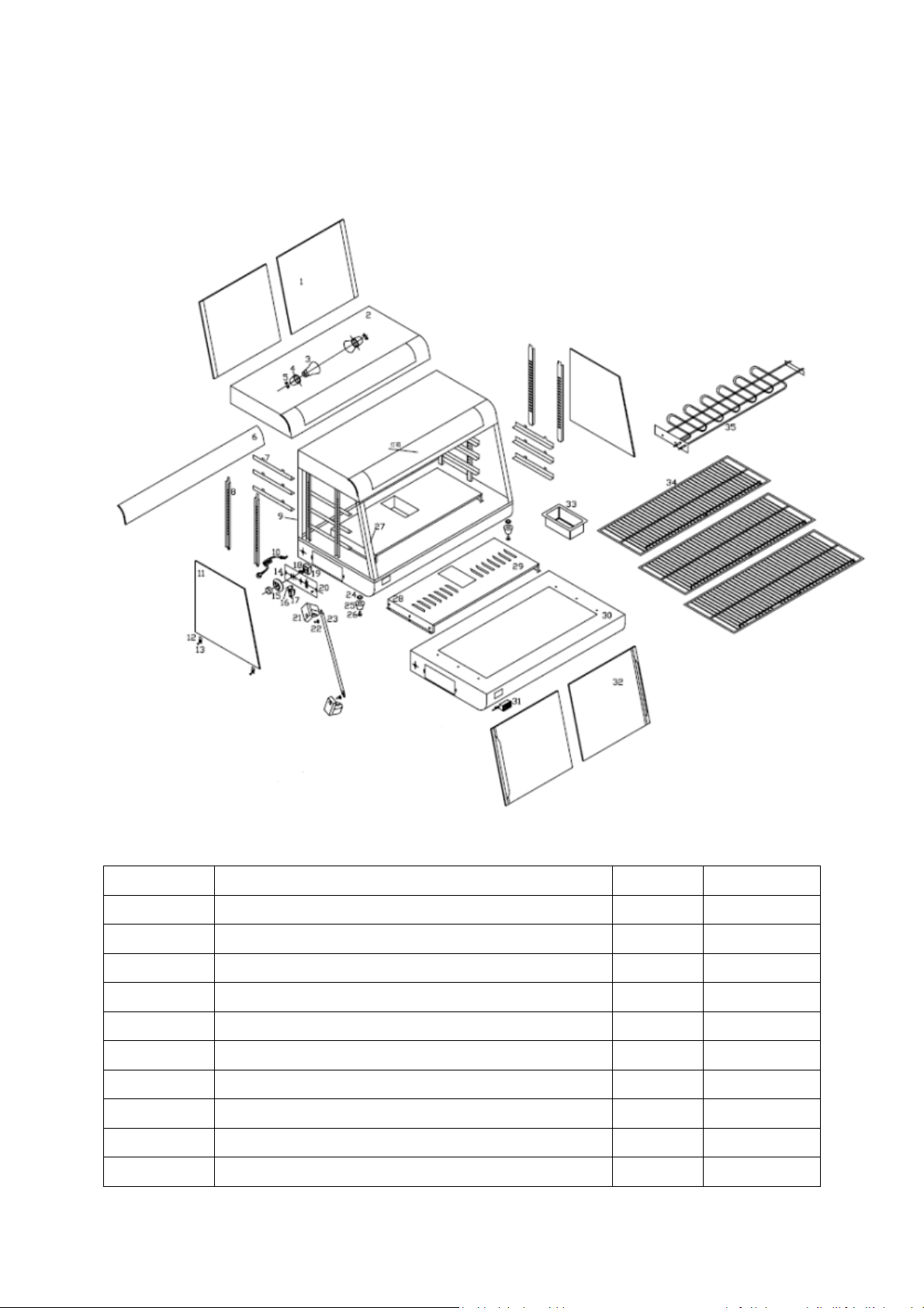
Parts Diagram
No. Description Quantity
1 Inclined glass 2 δ=5
2 Top cover 1
3 Illuminator 2
4 Ceramic base for illuminator 2
5 Fixing screw of ceramic base 4
6 Decoration board 1
7 Layer pallet 6
8 Supporting column of grid 4
9 Straight faced column 2
10 Power cord with jacket 1
Remark
Page 7
11 Side glass 2
12 Presser bit of glass 4
13 Fixing screw for presser bit of glass 4
14 Fixing screw for controlling board 2
15 Thermostat knob 1
16 Indicator 1
17 Switch 1
18 Thermostat 1
19 Fixing screw for thermostat 2
20 Controlling board 1
21 Illuminator 2
22 Ceramic base 4
23 Fixing screw of ceramic base for illuminator 4
24 Fixing nut for rubber foot 4
25 Rubber foot 4
26 Fixing screw 4
27 Sloping post 2
28 Fixing screw 6 M4×8
29 Safeguard for heating elements 1
30 Bottom board 1
31 Temperature display 1
32
33 Water vessel 1
34 Grid 3
35 Heating elements 1
Door glass(with handle and rubber sealing
2
gasket)
Each one
for 3 kinds
220V(R60-
3)
 Loading...