

Page 1
Page 2
User Manual
(Hardware)
UML290
Page 3

CHAPTER 1
BEFORE USING UML290 .....................................................................................................3
ABOUT THIS USER MANUAL ..................................................................................................................................................... 4
PRODUCT OVERVIEW ................................................................................................................................................................4
WHAT’S INSIDE THE PRODUCT PACKAGE.................................................................................................................................4
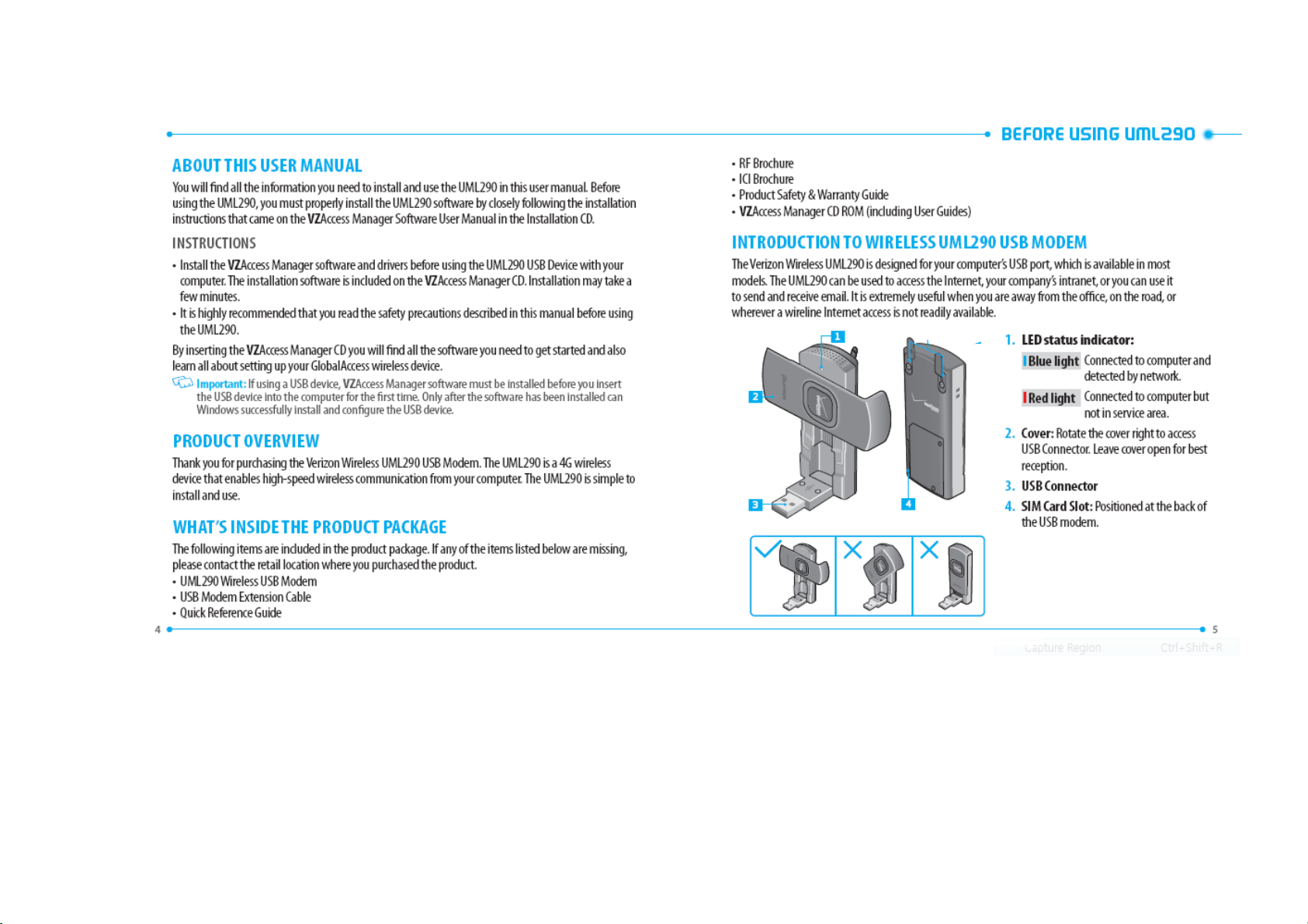
INTRODUCTION TO WIRELESS UML290 USB MODEM ............................................................................................................5
PRODUCT FEATURES ..................................................................................................................................................................6
PRODUCT HANDLING ................................................................................................................................................................7
CONFIGURATION ........................................................................................................................................................................7
CHAPTER 2
INSTALLING UML290 .........................................................................................................9
PRECAUTIONS ..........................................................................................................................................................................10
RECOMMENDED SYSTEM REQUIREMENTS ...........................................................................................................................10
INSTALLING THE 4G SIM CARD ...............................................................................................................................................11
REMOVING THE 4G SIM CARD.................................................................................................................................................11
INSTALLING VZACCESS MANAGER .........................................................................................................................................12
INSERTING AND REMOVING UML290 ................................................................................................................................... 13
USB MODEM EXTENSION CABLE ACCESSORY ...................................................................................................................... 14
CHAPTER 3
REGULATORY AND SAFETY INFORMATION ......................................................................15
REGULATORY NOTICES ............................................................................................................................................................16
OPERATING CONDITIONS ........................................................................................................................................................16
WARNINGS AND CAUTIONS ....................................................................................................................................................17
SAFETY PRECAUTIONS ...........................................................................................................................................................19
CHAPTER 4
APPENDIX ......................................................................................................................21
GLOSSARY .................................................................................................................................................................................22
SPECIFIC ABSORPTION RATES SAR ......................................................................................................................................25
SAFETY INFORMATION FOR RF EXPOSURE............................................................................................................................26
DECLARATION OF CONFORMITY R & TTE ............................................................................................................................29
BEFORE USING UML290
ABOUT THIS U SER MANUAL
PRODUCT OVERVIEW
WHAT’S IN SIDE THE PRO DUCT PACKAGE
INTRODUC TION TO WIRELES S UML290 USB M ODEM
PRODUCT F EATUR ES
PRODUCT H ANDLING
CONFI GURATION
UML290
1
2
Page 4
Page 5

For optimal reception, keep the cover open at a ninety degree angle.
Closing the cover will block the intenna, minimizing network access.
PRODUCT FEATURES
• Power management: The UML290 utilizes power management and system overhead reduction
functions provided by the USB interface for maximum power savings.
• Antenna design: Ecient, innovative internal antenna design optimizes data transfer rate and
sensitivity to network signals.
• Extension Cable: Simply insert the USB connector into the USB port of your computer to increase RF
performance and to solve clearance issues.
• USB Modem that supports Type A USB Port interface.
Important:
connection to the so-called power USB is prohibited.
• LTE(700)+ EVDO Rev.A(800/1900)
• Utilizes QUALCOMM MDM 9600 chip set.
• Supports 4G and 3G network technologies.
• Data Speeds
LTE bands : Typical download speeds of up to 25 to 50 Mbps in Mobile Broadband coverage area.
CDMA bands: Typical download speeds of 600 Kbps to 1.4 Mbps and upload speeds of 500 to 800
Kbps in Mobile Broadband coverage area.
• Supports Windows XP, Vista and 7 systems with installed host software and driver.
Note that the USB Modem MUST be connected to USB interfaces USB 2.0 or higher. The
BEFORE USING UML290
PRODUCT HANDLING
1. Do not put any adhesive label on the USB connector. It may leave a sticky residue that can cause
problems inside the computer USB port.
2. The UML290 USB device should easily slide into the USB port. Do not force the UML290 into the USB
port as it may cause damage to the modem and/or the port.
3. Keep the UML290 in a dry and clean place.
(Storage temperature: -22°F to 149°F [- 30°C to 65°C]). Keep your device away from liquids, dust and
excessive heat.
CONFIGURATION
To use the UML290, you should rst install the software included in the Installation CD and congure
the UML290 USB device. See the next section for more information on software installation and USB
device conguration.
7
6
Page 6

INSTALLING UML290
RECOM MENDED SYSTEM REQUIREMENTS
INSTALLING THE 4G SIM CAR D
REMOV ING THE 4G SIM CAR D
INSTALLING VZ ACCESS MANAG ER
INSERTING AND R EMOVING UML290
USB MODEM EXTE NSION CABLE ACCESSORY
UML290
2
PREC AUTIONS
Page 7

INSTALLING UML290
PRECAUTIONS
Insert the Installation CD and install the software on your computer before using the UML290 USB
modem. Follow the auto prompts. When you complete the software installation, you are ready to use
this device as USB modem.
RECOMMENDED SYSTEM REQUIREMENTS
To successfully install and use the UML290 USB device in your computer, the following system
specications are required.
Item Required Specication
• Operating system Windows® XP (Home, Professional or Tablet), Windows® Vista,
and Windows 7
• Port One Type-A USB Port
• Processor 150MHz or faster
• Memory 64 MB
• Disk space 28.1MB
• Dial-up networking DUN bound to TCP/IP
• CD ROM
INSTALLING THE 4G SIM CARD*
If not already done so, please follow these instructions for the installation of your new 4G SIM Card.
1. Open the protective cover with your ngertip.
2. Insert the 4G SIM Card into the slot with the contact points (typically
gold) facing towards the USB modem.
3. Gently push the 4G SIM Card in until it clicks into place and close the
card slot.
The SIM card must remain in the wireless USB modem while in use.
*A Subscriber Identity Module (SIM Card) is a “smartcard” that houses personal information, such as your
mobile phone number, calling plan, account information, and content, such as contacts, text messages,
and call history.
The Verizon Wireless 4G SIM Card is compatible with any Verizon Wireless 4G certied device. You can
move the 4G SIM Card from one device to another and your wireless service will work seamlessly as long
as you have a compatible device and service plan. To see which devices are compatible with the Verizon
Wireless 4G SIM Card, visit verizonwireless.com/certieddevice.
REMOVING THE 4G SIM CARD
1. Open the protective cover with your ngertip.
2. Gently push in the 4G SIM Card one time to pop it loose.
3. Carefully pull out the 4G SIM Card and close the protective cover.
Should your SIM Card be lost or damaged visit verizonwireless.com/myverizon to order a replacement
SIM. You can also call 1-800-922-0204 to speak with a Customer Service Representative. For toll-free
support outside of the U.S. call +1-908-559-4899 for 24/7 global support. For additional information
about 4G SIM Cards, visit verizonwireless.com/4GSIM.
11
10
Page 8

INSTALLING UML290
INSTALLING VZACCESS MANAGER
Follow these steps to install VZAccess Manager:
1. Insert the VZAccess Manager CD into the your computer.
2. Click the I nstall VZAccess Manager setup program. A “Welcome” screen appears. Click the Next
button to continue with the installation process.
3. A License A greement dialog box appears. I f you agree to the terms, click I agree… followed by
Next to continue.
4. You can choose to create a VZAccess Manager shortcut on your desktop by selecting Install
Desktop Shortcut button. Click Next.
5. It is recommended that you leave the default path as is and click Next.
6. Click Next to start the installation process.
After the les are copied to your computer, the Installation Complete dialog box appears. When you
press Finish, VZAccess Manager automatically starts.
On most computers, VZAccess Manager launches automatically on your screen once the software
is properly installed. If VZAccess Manager does not open automatically, you can launch it from your
Start menu (Windows).
INSERTING AND REMOVING UML290
• It is normal to hear a short beep sound each time you insert or remove the UML290. It is an audible
notication that your PC recognizes the new hardware.
• After your session is over and you disconnect from the network, you’re ready to safely remove your
wireless device.
When removing the UML290, always grip the top and bottom of the modem and push/pull gently.
13
12
Page 9

USB MODEM EXTENSION CABLE ACCESSORY
An extension cable is included to optimize the performance of your UML290 USB modem. This cable
increases the distance between your USB modem and computer, reducing possible interference from
your computer.
HOW TO USE THE EXTENSION CABLE:
1. Insert your USB modem into the wide end of the cable connector clip and extend the USB modem
away from your computer. (Or, you can use the built-in clip to hook the USB modem over the top of
your computer screen)
2. Plug the USB connector into the USB port on your computer.
3. Your USB modem is powered by your computer as soon as the USB cable is plugged properly into the
USB port.
4. Launch VZAccess Manager and click Connect.
REGULATORY AND
SAFETY INFORMATION
REGULATORY NOTIC ES
OPER ATING CONDI TIONS
WARNINGS AND CAUT IONS
SAFETY PRECAU TIONS
UML290
3
14
Page 10

REGULATORY AND SAFETY INFORMATION
REGULATORY NOTICES
UML290 complies with Parts 15,22 and 24, 27 of the FCC rules. It has been tested with the typical
personal computer with a USB port. This USB device must not be co-located or operated in conjunction
with any other antenna or transmitter. If you use this USB device in any other conguration, the FCC RF
Exposure compliance limit can be exceeded.
OPERATING CONDITIONS
1. This device may not cause harmful interference, and must accept any interference received,
including interference that may cause undesirable operations.
WARNINGS AND CAUTIONS
1. Modifying or changing this USB device without express authorization can nullify compliance with RF
exposure guidelines.
2. This USB device has been tested and found to comply with the limits pursuant to Part 15,22 and
24, 27 of the FCC Rules. These limits are designed to provide reasonable protection against harmful
interference when appropriately installed. This USB device generates, uses, and can radiate radio
frequency and, if not installed and used according to the instructions provided, it may cause harmful
interference to radio communication. However, there is no guarantee that interference will not occur
in any particular installation.
3. If this USB device does cause harmful interference with radio or television signals (determine this by
turning the USB device o and on), attempt to correct the interference by trying one or more of the
following:
• Increase the separation between the USB device and receiver.
• Connect the USB device into an outlet on a circuit dierent from that to which the receiver is
connected.
• Consult the dealer or an experienced radio/TV technician for help.
4. This USB device does not exceed the Class B limits for radio noise emissions from digital apparatus as
set out in the interference causing equipment standard entitled “Digital Apparatus”, ICES-003 of the
Department of Communications.
5. If you have purchased this product under a United States Government contract, it shall be subject
to restrictions as set forth in subparagraph (C)(1)(ii) of Defense Federal Acquisitions Regulations
(DFARs) Section 252.227-7013 for Department of Defense contracts, and as set forth in Federal
Acquisitions Regulations (FARs) Section 52.227-19 for civilian agency contracts or any successor
regulations. If further government regulations apply, it is your responsibility to ensure compliance
with such regulations.
17
16
Page 11

REGULATORY AND SAFETY INFORMATION
* WARNING: This product contains a chemical known to the State of California to cause cancer.
* WARNING: This product contains a chemical known to the State of California to cause birth defects or
other reproductive harm.
SAFETY PRECAUTIONS
1. Data transmission and reception cannot be guaranteed because of the nature of wireless
communications. Data can be delayed, corrupted or lost during transmission. Even though it is quite
rare that signicant data delay or loss occurs if the USB device is used in a normal manner, this USB
device should not be used in cases that data transmission or reception failure could result in damage
of any kind to the user or another party, including but not limited to personal injury, death or loss
of personal property. Personal Communications Devices, LLC., bears no responsibility for damages
or losses of any kind resulting from delays or errors in data transmission using the USB device, or for
failure of the USB device to transmit or receive such data.
2. Do not use this USB device in areas where blasting is in progress, where explosive atmospheres
may be present, near medical equipment, life support equipment, or any equipment which may
be susceptible to any form of radio interference. Turn o this USB device in these areas, since it can
transmit signals that could interfere with this equipment.
3. Do not use this USB device in any aircraft whether the aircraft is on the ground or in ight. Make sure
to turn o this USB device in aircraft.
If used in an aircraft, it can transmit signals that could interfere with various aircraft systems.
4. Do not use this USB device while driving a car, since it can distract the driver. In some area, using the
communication device while driving a car is illegal.
19
18
Page 12

SAFETY INFORMATION FO R RF EXPOSURE
DECL ARATION OF CONFORMITY R & TTE
UML290
APPENDIX
SPECIFIC ABSORPTION RATES SAR
4
GLOSSARY
Page 13

GLOSSARY
Analog Coverage
An area where analog service is available. Analog phones usually indicate signal strength on an
indicator in the phone’s display when receiving an analog signal.
Browser
The software that allows you to view the Internet; contains navigator commands such as forward and
back; examples include Netscape, Microsoft Explorer. A Web browser in your computer requests HTML
les from Web servers and takes you to the Internet sites you wish to visit, by linking your computer’s IP
address to a site’s IP address.
COM PORT (communications port)
A connector for a communications interface, usually, a serial port.
Data
Information kept in databases, on an intranet, on the Internet, etc.
Driver
Software that controls a device.
Inactivity Time-Out
A stoppage in a connection, which usually occurs after a period of time elapses, without activity. Timeout settings are usually determined by the network.
Internet
A cooperatively run, globally distributed collection of computer networks that exchange information
via a common set of rules for exchanging data (Transfer Control Protocol/Internet Protocol or TCP/IP).
Intranet
An intranet is a web site created by a business, which posts its own company information in a secure
part of the Internet that only employees or other authorized users can reach. Intranets are generally
protected by rewalls.
APPENDIX
Kbps
Kilobits per second.
Kilobyte (KB)
1024 bits (Approximately 1/2 page of plain text)
Modem
Hardware that translates and transmits data over wire-line or wireless.
Package Minutes
Package minutes are those minutes included in the cost of a monthly service plan. Once the packaged
minutes have been exhausted, additional airtime charges apply. Please refer to Plans and Pricing for
more information, details and oers in your area.
Packet Switching
Packet-switching messages are divided into packets or pieces before transmission over one or more
routes and are reassembled at their destination.
POP3 e-mail
Protocol used by ISP’s mail servers to manage e-mail for subscribers. E-mail clients such as Microsoft
Outlook support POP3.
Proxy Settings
A specic IP (Internet Protocol) address that allows access to a secured enterprise network. The proxy
settings provide directions to a computer so that it can locate an address and access information and
services, which exist at that location.
Search Engine
A program that receives a user’s search request, compares it to the entries in the index, and returns
results to help the user nd relevant information.
Serial Port
A connector on a computer used to connect peripherals, which communicate using a serial protocol.
23
22
Page 14

Serial/Data Cable
A wire that connects two serial ports carrying data to one another.
Transmission Speed
The rate at which data is sent over a communications line, usually measured in kilobits (kbps).
USB Cable
A wire connecting USB port carrying a data.
USB Port
A connector on a computer to connect peripherals using USB (Universal Serial Bus) protocol.
APPENDIX
SPECIFIC ABSORPTION RATES SAR
Maximum: SAR 0.696 W/kg CDMA835 Body
SAR 1.02 W/kg PCS CDMA 1900 Body
SAR 0.569 W/kg WCDMA850 Body
SAR 0.989 W/kg WCDMA1900 Body
SAR 0.539 W/kg GSM 850 Body
SAR 1.03 W/kg GSM 1900 Body
SAR 1.15 W/kg LTE Body
THIS MODEL DEVICE MEETS THE GOVERNMENT’S REQUIREMENTS AND EUROPEAN UNION (EU)
STANDARDS FOR EXPOSURE TO RADIO WAVES.
Device is a radio transmitter and receiver. It is designed and manufactured not to exceed the emission
limits for exposure to radiofrequency (RF) energy set by the Federal Communications Commission of
the U.S. Government. These limits are part of comprehensive guidelines and establish permitted levels
of RF energy for the general population. The guidelines are based on standards that were developed by
independent scientic organizations through periodic and thorough evaluation of scientic studies. The
standards include a substantial safety margin designed to assure the safety of all persons, regardless
of age and health. The exposure standard for Device employs a unit of measurement known as the
Specic Absorption Rate, or SAR. The SAR limit set by the FCC is 1.6 W/kg* and EU standards is 2.0
W/10kg.
Tests for SAR are conducted with the Device transmitting at its highest certied power level in all tested
frequency bands. Although the SAR is determined at the highest certied power level, the actual SAR
level of the Device while operating can be well below the maximum value. This is because the Device is
designed to operate at multiple power levels so as to use only the power required to reach the network.
In general, the closer you are to a wireless base station antenna, the lower the power output. Before
a Device model is available for sale to the public, it must be tested and certied to the FCC that it does
not exceed the limit established by the government adopted requirement for safe exposure. The tests
are performed in positions and locations as required by the FCC for each model. The highest SAR value
25
24
Page 15

for this model Device when tested for use at the when used near the body, as described in this user
guide, is 1.15W/Kg. (Body SAR measurements dier among Device models, depending upon available
accessories and FCC requirements). While there may be dierences between the SAR levels of various
Device and at various positions, they all meet the government requirement for safe exposure. The FCC
has granted an Equipment Authorization for this model Device with all reported SAR levels evaluated
as in compliance with the FCC RF exposure guidelines. SAR information on this model Device is on le
with the FCC and can be found under the Display Grant section of http://www.fcc.gov/oet/fccid after
searching on FCC ID: JYCRAY.
Additional information on Specic Absorption Rates (SAR) can be found on the Cellular
Telecommunications Industry Association (CTIA) web-site at http://www.wow-com.com.
* In the United States and Canada, the SAR limit for Device used by the public is 1.6 w/kg (W/kg)
averaged over one gram of tissue. The standard incorporates a substantial margin of safety to give
additional protection for the public and to account for any variations in measurements.
The Declaration of Conformity at the back of this guide demonstrates your device’s compliance with the
European Radio & Terminal Telecommunications Equipment (R&TTE) directive.
SAFETY INFORMATION FOR RF EXPOSURE
NEAR BODY OPERATION
This Mobile Broadband USB Modem, model UML290, is approved for use in normal size laptop
computers only (typically with 12” or larger display screens). To comply with FCC RF exposure
requirements, this modem should not be used in congurations that cannot maintain at least 5mm
(approximately 0.2 inches) from your body (The test was performed with a belt clip that provided a
15mm for CE certication).
Also, when using the USB extension cable, place the USB modem away from your body or any other
transmitter of the laptop or PC.
APPENDIX
This USB modem has been tested for compliance with FCC/IC RF exposure limits in the laptop
computers congurations with horizontal and vertical USB slots and can be used in laptop computers
with substantially similar physical dimensions, construction and electrical and RF characteristics.
When using this USB modem in your computer, it must not be co-located or simultaneously transmit
with any other radio (for example, Bluetooth or WiFi radios) in the computer.
SAFETY INFORMATION
SAFETY INFORMATION FOR FIXED WIRELESS TERMINALS POTENTIALLY EXPLOSIVE ATMOSPHERES
Turn your device OFF when in any area with a potentially explosive atmosphere and obey all signs and
instructions. Sparks in such areas could cause an explosion or re resulting in bodily injury or even
death.
INTERFERENCE TO MEDICAL DIVICES
Certain electronic equipment may be shielded against RF signal from you device (pacemakers,
Hearing Aids, and so on). Turn your device OFF in health care facilities when any regulations posted in
these areas instruct you to do so. RF signals may aect improperly installed or inadequately shielded
electronic system in motor vehicles.
FCC COMPLIANCE INFORMATION
This device complies with Part 15 of FCC Rules.
Operation is subject to the following two conditions:
(1) This device may not cause harmful interference.
(2) This device must accept any interference received.
Including interference that may cause undesired operation.
27
26
Page 16

APPENDIX
PART 15.21 STATEMENT
“Change or Modications that are not expressly approved by the manufacturer could void the user’s
authority to operate the equipment.”
PART 15.105 STATEMENT
This equipment has been tested and found to comply with the limits for a class B digital device,
pursuant to Part 15 of the FCC Rules.
These limits are designed to provide reasonable protection against harmful interference in a
residential installation. This equipment generates uses and can radiate radio frequency energy and,
if not installed and used in accordance with the instructions, may cause harmful interference to
radio communications. However, there is no guarantee that interference will not occur in a particular
installation. If this equipment does cause harmful interference or television reception, which can
be determined by turning the equipment o and on, the user is encouraged to try to correct the
interference by one or more of the following measures:
- Reorient or relocate the receiving antenna.
- Increase the separation between the equipment and receiver.
- Connect the equipment into an outlet on a circuit dierent from that to which the receiver is
connected.
- Consult the dealer or an experienced radio/TV technician for help.
DECLARATION OF CONFORMITY R & TTE
We, PANTECH WIRELESS, INC. declare under our sole responsibility that the product
Product Name: UML290
Product Type: USB Modem
to which this declaration relates, is in conformity with the following
standards and/or other normative documents.
SAFETY EN 60950-1 : 2001 + A11 :2004
EMC EN 301 489-1 V 1.6.1 (2005-09)
EN 301 489-7 V 1.3.1 (2005-11)
EN 301 489-24 V 1.3.1 (2005-11)
SAR EN 50360: 2001 & EN 62209-1: 2006
RADIO EN 301 511 V9.0.2 (03-2003)
EN 301 908 – 1 V3.2.1 (05-2007)
EN 301 908 – 2 V3.2.1 (05-2007)
We hereby declare that (all essential radio test suites have been carried out and that) the above named
product is in conformity to all the essential requirements of Directive 1999/5/EC.
The conformity assessment procedure referred to in Article 10 and detailed in Annex (III) or (IV) of
Directive 1999/5/EC has been followed with the involvement of the following Notied Body(ies):
PHOENIX, Koenigswinkel 10 32825 Blomberg Germany
Identication mark: 0700
(Phoenix Notied Body number)
29
28
 Loading...