

Panoramic h-line Assembly Manual
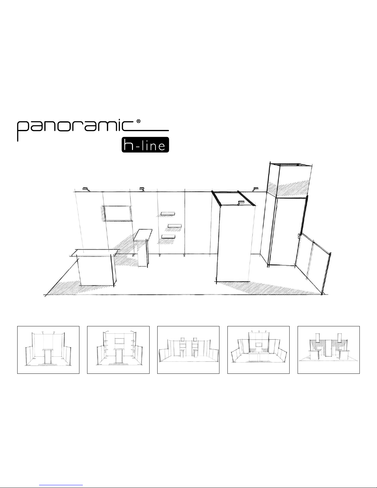
Assembly Instructions
MKG_NA-ENG_Instructions_H-line_V16_20170731
Bu t also...
Thank you,
for choosing
‘‘
’’
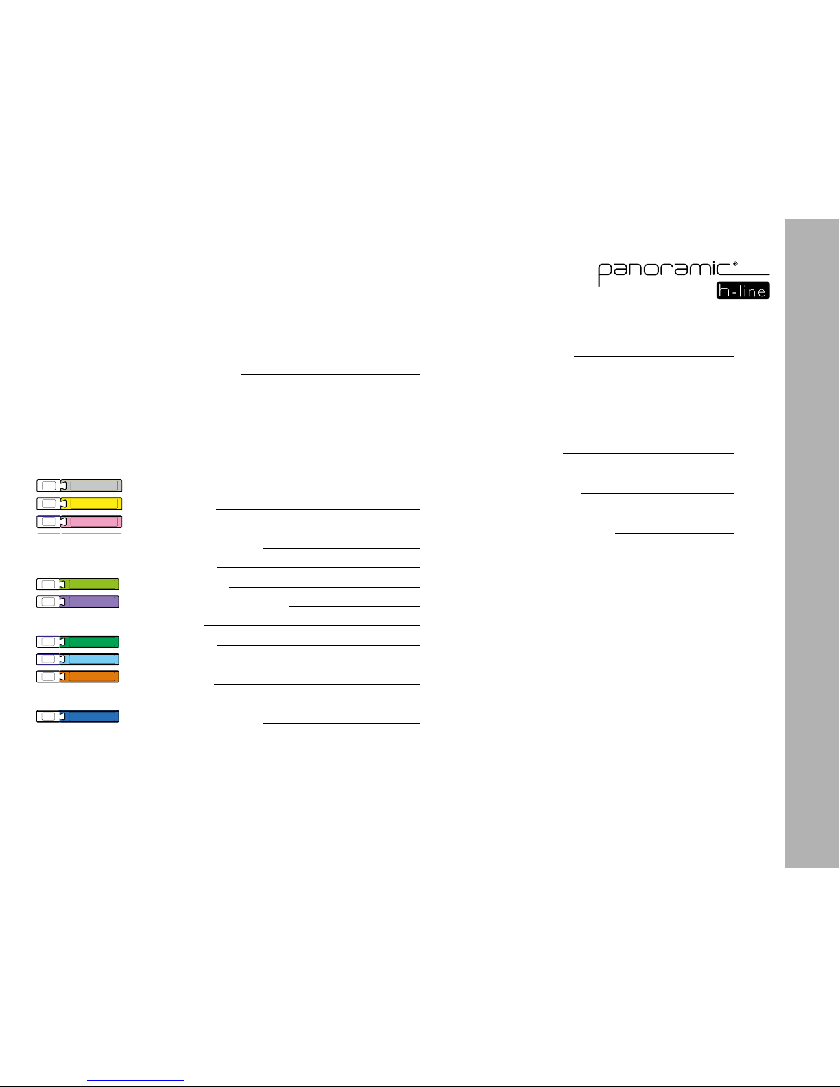
3
Finishing Touches 28
Feet
Prole Covers
Shelves 29
Universal attachment piece
Brochure holder 30
Hanging Rod
Free-Standing Shelf 31
LED Lights
Power Supply Attachment 32
Graphics 33
Table of Contents
YELLOW
N°
GREY
N°
PINK
N°
YELLOW
N°
GREY
N°
PURPLE
N°
GREEN
N°
PINK
N°
YELLOW
N°
GREY
N°
DARK GREEN
N°
PURPLE
N°
ORANGE
N°
N°
LIGHT BLUE
GREEN
N°
PINK
N°
YELLOW
N°
GREY
N°
DARK GREEN
N°
PURPLE
N°
ORANGE
N°
N°
LIGHT BLUE
GREEN
N°
PINK
N°
BROWN
N°
BLUE
N°
Identication of the Crate 4
Assembly Guidelines
5
Smart, optimized storage
6
Module Color-Coding and Chronology (Example)
7
Connecting Frames
8
Standard Lightbox Module 10
Angled Module
11
Closet Module 12
Storage Module (38x38)
13
Storage Module (38x76)
14
Shelving Module
15
Multimedia Module
16
Multimedia Module - Touchpad 17
Arch Module
19
Console Module
21
Header Module
23
Signage Module 25
Counter Module
26
Counter Module (Door)
26
Connection Module 27
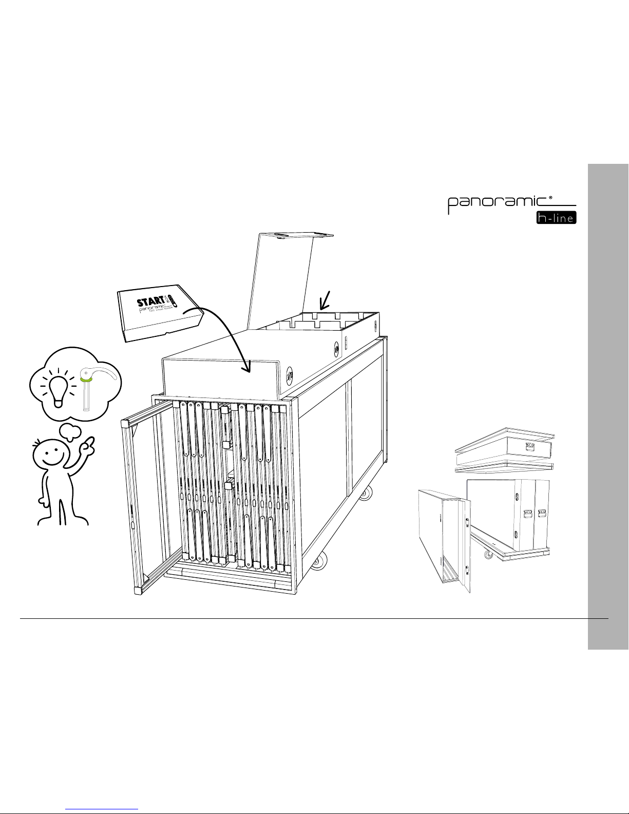
4
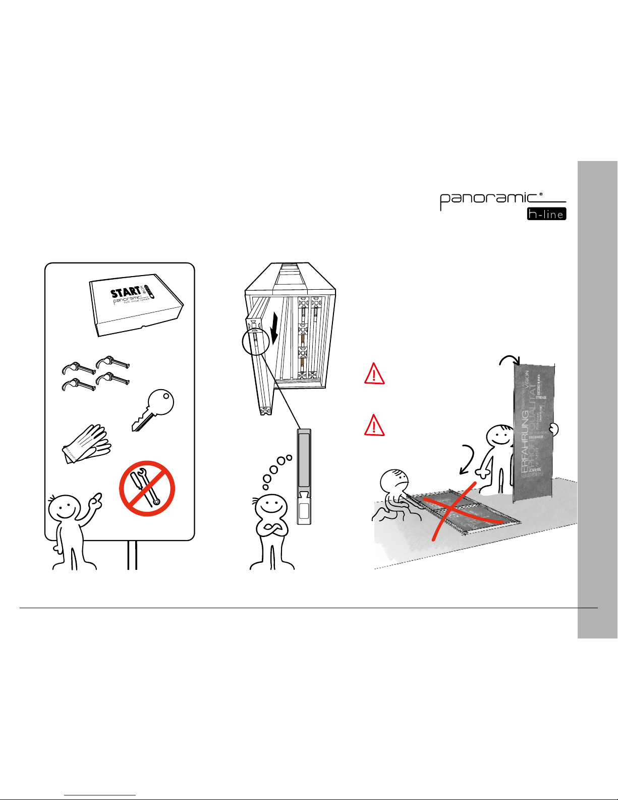
Identification of the Crate
H3 CRATE
CONNECTORS
ACCESSORIES
FURNISHINGS
Use a h-line
connector to
extract the rst
frame.
H5 CRATE
5
1
3
4
52
1
2
Assembly Guidelines
3
1
Do not disassemble the frame
or remove the graphic
Do not place the frame
on the ground graphic
side down
6
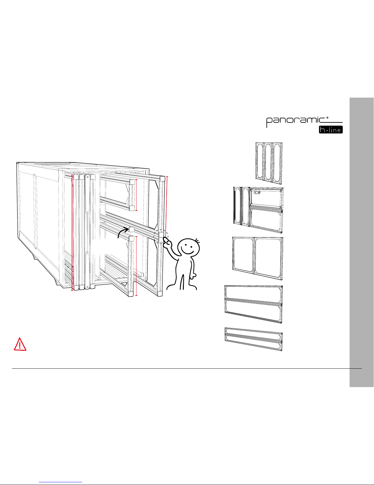
Smart, optimized storage
FRAME CONNECTION
19"
19"
9.5"
Some frames are
connected during
shipping
Angled pole
storage
38"
Counter Module
Header Module
Standard Module
19"
Standard Module
9.5"
To disconnect the frames, refer to the corresponding modules
(see table of contents)
Console Module
7
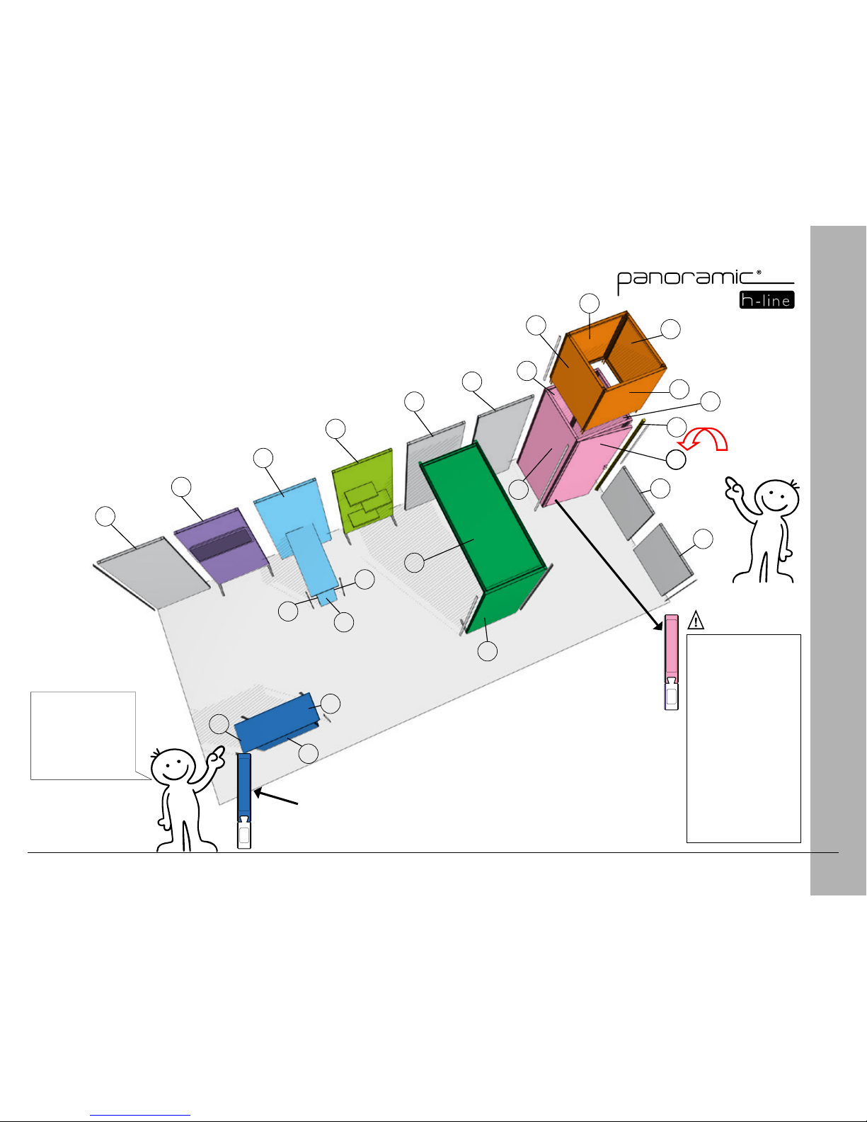
Module Color-Coding and Chronology
(Example)
BLUE
N°
DARK GREEN
N°
PURPLE
N°
ORANGE
N°
N°
LIGHT BLUE
GREEN
N°
PINK
N°
BROWN
N°
BLUE
N°
Look at module
colors on your
booth rendering
and refer to the
corresponding pages.
18
17
16
1
2
19
20
21
22
3
4
5
6
15
14
7
8
9
24
25
23
10
11
12
13
Start Here
1. Find the "Start
Here" arrow on your
booth rendering
2. Locate frames in
the crate using the
numbering system
3. Look at the frame's color
4. Locate the page
with the corresponding
color in the
instructions
5. Assemble your
stand following the
chronological order
8
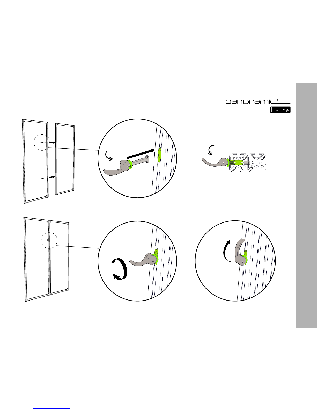
Connecting Frames
3
1
2
Insert
1/4 turn
Lock
Open completely
Connector
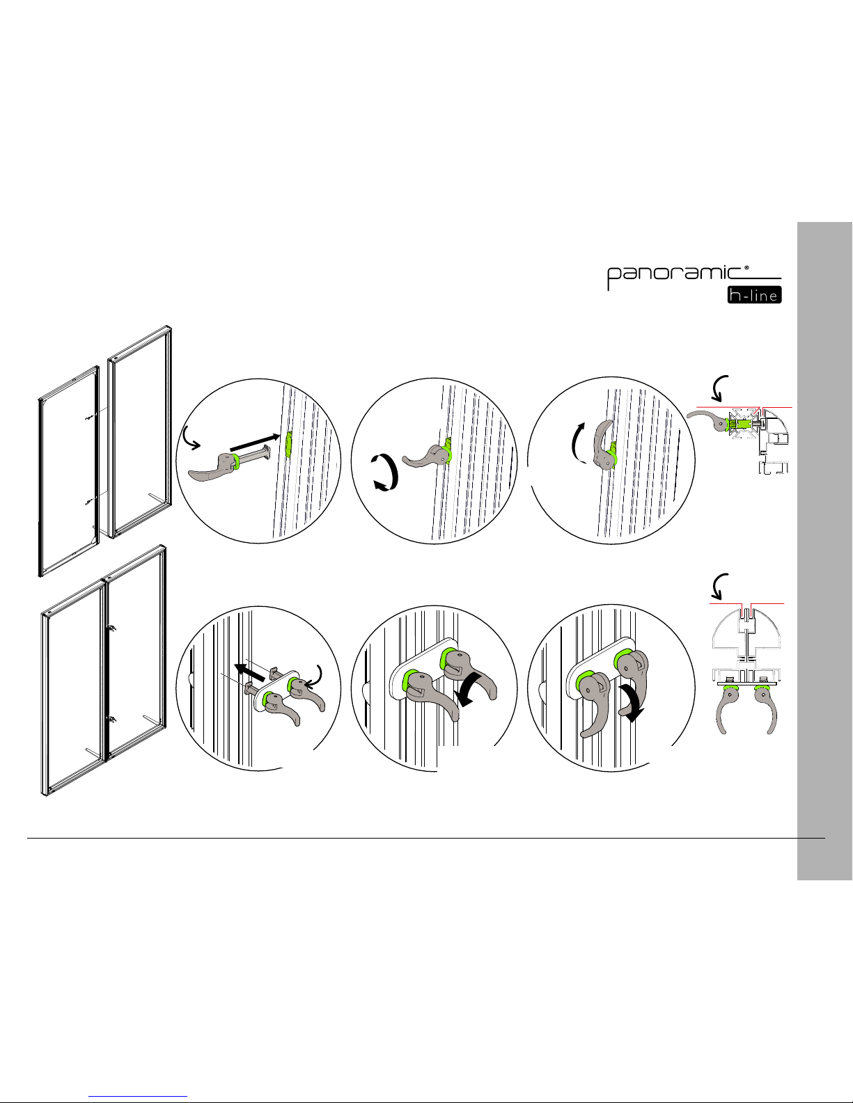
9
Connecting Lightbox Frames
1
1
3
3
2
2
Insert
Standard frame / lightbox connection
Insert
1/4 turn
1/4 turn
Lock
Lock
Open completely
Open completely
Lightbox / lightbox connection
Connector
Connector
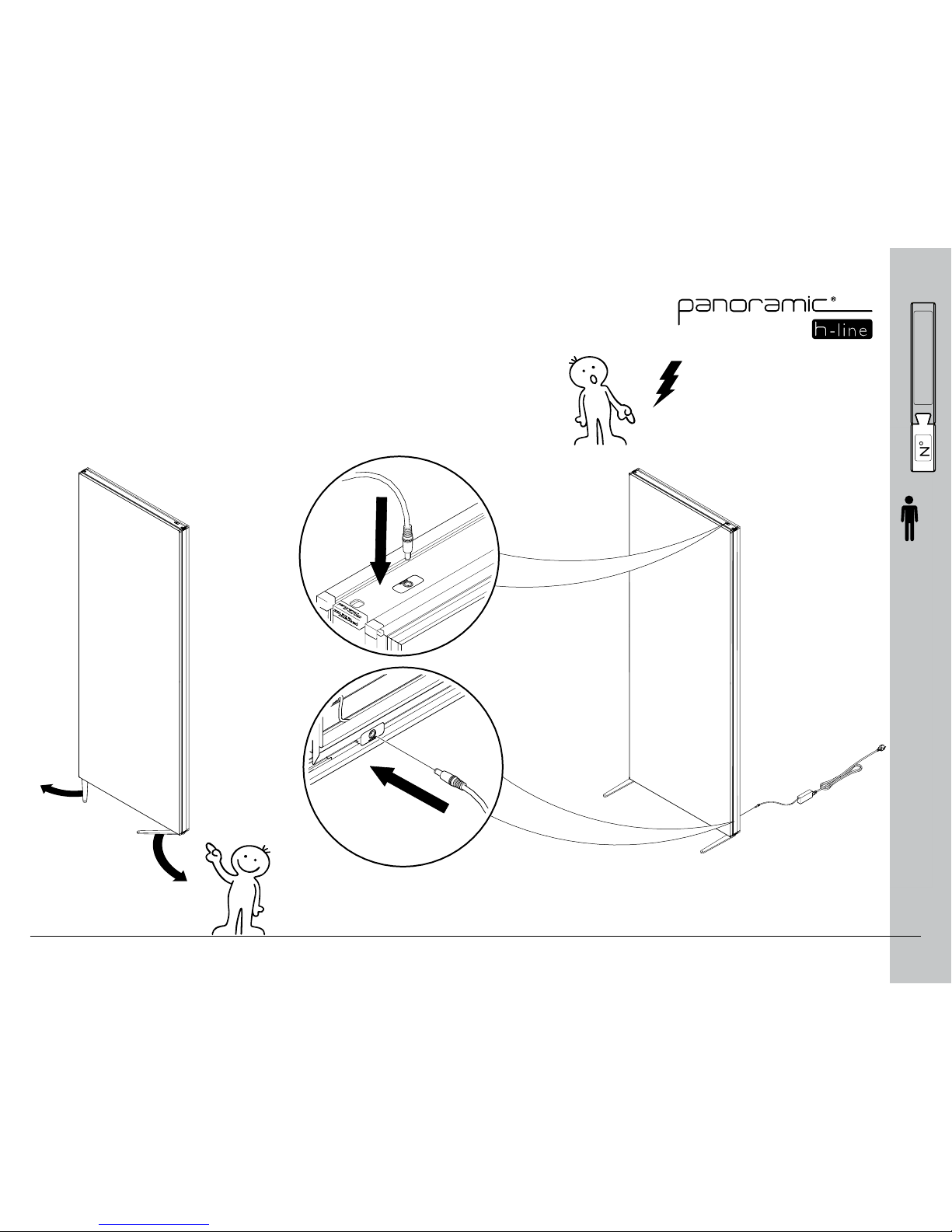
10
Standard Lightbox Module
1 Rotate feet 2 Plug
YELLOW
N°
GREY
N°
DARK GREEN
N°
PURPLE
N°
ORANGE
N°
N°
LIGHT BLUE
GREEN
N°
PINK
N°
BROWN
N°
BLUE
N°
(optional)
x1
or
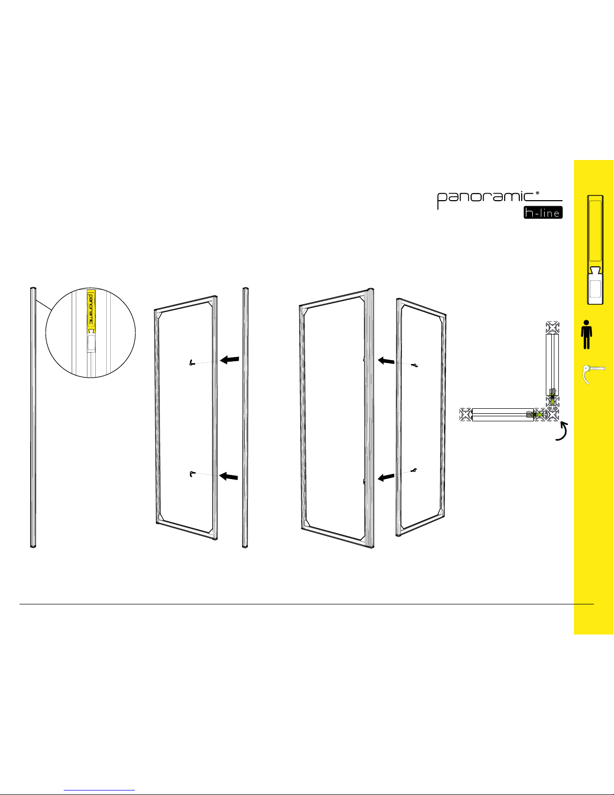
11
Angled Module
Angled pole
1 Identify 2 Attach
3 Connect
x1
YELLOW
N°
DARK GREEN
N°
PURPLE
N°
ORANGE
N°
N°
LIGHT BLUE
GREEN
N°
PINK
N°
BROWN
N°
BLUE
N°
x4
 Loading...