

Page 1

Industrial Distribution Frame and
Universal Distribution Frame
Thermal Management
Network enclosures are widely used both indoors and outdoors to secure a
wide range of electronic equipment such as switches, routers, gateways, power
supplies, etc. These enclosures are used in a wide range of markets including
hospitals, manufacturing plants, reneries, stadiums, etc. Therefore, these
enclosures are exposed to a wide variety of ambient conditions.
Such enclosures (Figure 1) can have strict ingress ratings such as NEMA
4/4X, IP54/55, etc. These ratings, while protecting the equipment from
some environmental conditions (dust, water spray, etc.), also effectively trap
the heat dissipated by the active equipment inside the enclosure. This air,
that has increased in temperature, must still provide adequate cooling for
the components mounted inside the enclosure.
APPLICATION
GUIDE
Figure 1: UDF 12 RU Universal
Distribution Frame
(front door removed).
This application guide gives an overview of key design considerations for thermal
management solutions to mitigate these thermal factors for Panduit’s UDF and
IDF enclosures. The capabilities of the various thermal management solutions
are discussed and guidelines for recommended solutions are provided.
Table of Contents
Application Guide .............................................1
Introduction ..................................................2
12 RU IDF/UDF Thermal Solutions .............................2 – 3
Deploying a Fresh Air/Vented Cooling System in a 12 RU IDF/UDF .........4
Deploying a T20 Air Conditioner in a 12 RU IDF/UDF .................4
26 RU IDF/UDF Thermal Solutions .............................5 – 6
Deploying a Fresh Air/Vented Cooling System in a 26 RU IDF/UDF ....... 7
Deploying a N28 Air Conditioner in a 26 RU IDF/UDF.................8
Rack Mounted IT Equipment ....................................8
Panduit Difference.............................................8
References...................................................8
The Information Contained In This
Application Guide Is Intended
As A Guide For Use By Persons
Having Technical Skill At Their Own
Discretion And Risk. Before Using
Any Panduit Product, The Buyer
Must Determine The Suitability Of
The Product For His/Her Intended
Use And Buyer Assumes All Risk
And Liability Whatsoever In
Connection Therewith. Panduit
Disclaims Any Liability Arising From
Any Information Contained Herein
Or For Absence Of The Same.
www.panduit.com
Page 2

Introduction
Most of the power consumed by electronic endpoint devices is dissipated as heat; this is especially true of IT
equipment (switches, servers, routers, etc.). To avoid equipment overheating or even failure, the cooling of this
equipment should be considered as part of the deployment plan. When an enclosure is placed in a high ambient
temperature environment, this choice further increases the need to consider cooling options for any enclosure. Given
the stringent sealing requirements for NEMA rated enclosures, the air inside is completely enclosed, severely limiting
the options for cooling the air. Some of the current cooling solutions in the market use fans and vents, small enclosure
mounted air conditioners, liquid-cooled heat exchangers, compressed air vortex tubes, etc. In the solutions section of
this document, some of the more practical thermal management solutions will be considered for Panduit’s Universal
Distribution Frame (UDF) and Industrial Distribution Frame (IDF) enclosures.
The solutions are based on maintaining the internal temperature of the enclosure below 60°C. This is the upper
temperature limit for most of the components in a typical UDF or IDF deployment with DIN rail mounted equipment.
The charts in the following sections illustrate the allowable ambient temperature outside an enclosure vs. a heat load
for various recommended cooling solutions.
12 RU IDF/UDF Thermal Solutions
12 RU UDF Cooling Solutions w/HD Patch Fields Optimal Range
55.00
50.00
45.00
40.00
35.00
30.00
Ambient Temperature (C)
25.00
20.00
0 50 100 150 200 250 300 350 400
Figure 2: 12 RU UDF enclosure guidelines for three recommended thermal solutions.
The examples below demonstrate how to use this graph.
Example 1: An electronic load of 100 watts (sum of heat dissipation of the electronics inside the UDF). A peak ambient temperature
of 35°C (temperature outside the enclosure).
Answer 1: The intersection of the vertical 100 w line and the horizontal 35°C line is in the blue area. Therefore, the UDF enclosure
will adequately dissipate the heat and the peak internal temperature inside the UDF will not exceed 60°C.
Example 2: An electronic load of 150 watts. A peak ambient temperature of 35°C (temperature outside the enclosure).
Answer 2: The intersection of the vertical 150 w line and the horizontal 35°C line is in the red area. Therefore, a fan and vent are
required to keep the internal temperature of the UDF enclosure below 60°C.
Example 3: An electronic load of 200 watts. A peak ambient temperature of 40°C (temperature outside the enclosure).
Answer 3: The intersection of the vertical 200 w line and the horizontal 40°C line is in the green area. Therefore, a T20 air
conditioner is required to keep the internal temperature of the UDF enclosure below 60°C.
60°C Peak Internal Temperature
T20 AC Unit
Fan and Vent HF10
Sealed Enclosure
Electronic Load (W)
Notes: Installing a fan and vent or air conditioner lowers the enclosure rating to IP54/IP55.
Installing DIN rail mounted equipment with an operating temperature less than 60°C will likely require an air conditioner
to avoid exceeding the temperature limits for the device in question (e.g. battery UPS).
Follow vendor recommendations for minimum clearances around active equipment (e.g. typically 2" for convection
cooled switches). Mount equipment with lower recommended operating temperatures on the lower DIN rails.
2
www.panduit.com
Page 3

12 RU IDF/UDF Thermal Solutions (continued)
12 RU IDF Cooling Solutions 60°C Peak Internal Temperature
55.00
50.00
45.00
40.00
35.00
30.00
Ambient Temperature (C)
25.00
20.00
0 50 100 150 200 250 300 350 400 450 500
Electronic Load (W)
T20 – 40C Equipment Intake
None – 60C Equipment Intake
None – 45C Equipment Intake
None – 40C Equipment Intake
IDF with 2 Catalyst 3850s and
1 UPS total IT equipment heat
load 305 watts
Figure 3: 12 RU IDF enclosure guidelines for recommended thermal solutions.
This graph is used in the same manner as the graph shown in Figure 2.
Notes: Installing a fan and vent or air conditioner lowers the enclosure rating to IP54/IP55.
Installing DIN rail mounted equipment with an operating temperature less than 60°C will likely require an air
conditioner to avoid exceeding the temperature limits for the device in question (e.g. battery UPS).
Follow vendor recommendations for minimum clearances around active equipment (e.g. typically 2" for convection
cooled switches). Mount equipment with lower recommended operating temperatures on the lower DIN rails
or racks.
www.panduit.com
3
Page 4
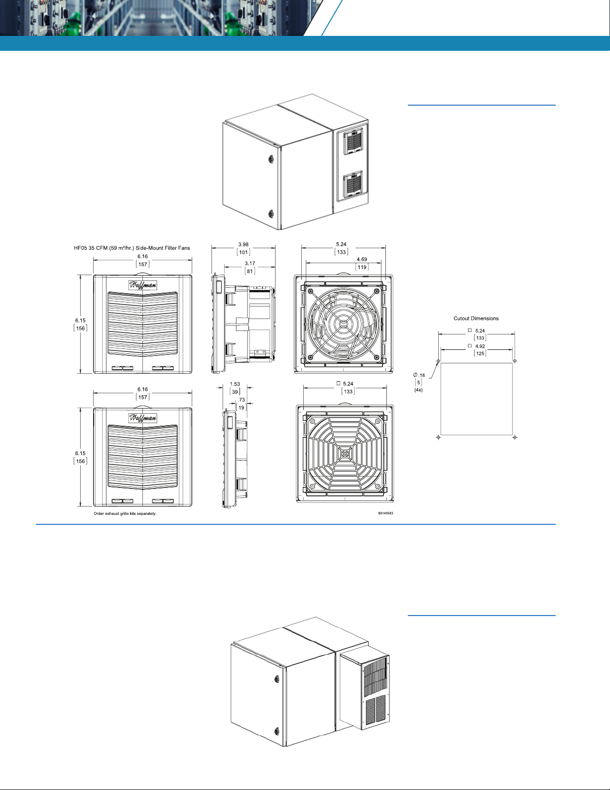
Deploying a Fresh Air/Vented Cooling System in a 12 RU IDF/UDF
Figure 4: 12 RU UDF enclosure
with vent and fan installed
on the gland plate. The
fan should be installed
in the lower position and
the vent in the upper
position. Reversing the
locations of the fan and
vent may reduce thermal
performance.
Figure 5: Dimensions of a HF05 exhaust fan and exhaust vent and cutout dimensions. The gland plate should be removed, and
the fan and vent cutouts made in the gland plate. These cutouts must be aligned with the openings already provided
in the enclosure for the T20 air conditioner. Mount the fan and vent to the gland plate then reattach the gland plate to
the enclosure.
Deploying a T20 Air Conditioner in a 12 RU IDF/UDF
Figure 6: 12 RU UDF shown with a
T20 AC unit. Remove the
The HF05 fans, vents, and the T20 air
conditioner are provided separately
from nVent|Hoffman. Complete
installation and operating guides are
provided by the manufacturer. Links
to these installation documents are
provided in the reference section.
4
www.panduit.com
gland plate and mount the
air conditioner aligned to
the holes provided in the
enclosure. The gland plate
is not required once the air
conditioner is installed on
the enclosure.
Page 5

26 RU IDF/UDF Thermal Solutions
12 RU UDF Cooling Solutions w/HD Patch Fields Optimal Range
60°C Peak Internal Temperature
Electronic Load (W)
T20 AC Unit
Fan and Vent HF10
Sealed Enclosure
55.00
50.00
45.00
40.00
35.00
30.00
25.00
20.00
0 50 100 150 200 250 300 350 400
Ambient Temperature (C)
50.00
45.00
40.00
35.00
30.00
Ambient Temperature (C)
25.00
20.00
Figure 7: 26 RU UDF enclosure guidelines for three recommended thermal
Example 1: An electronic load of 200 watts (sum of heat dissipation of the electronics inside the UDF). A peak ambient
temperature of 35°C (temperature outside the enclosure).
Answer 1: The intersection of the vertical 200 w line and the horizontal 35°C line is in the blue area. Therefore, the UDF enclosure
Example 2: An electronic load of 300 watts. A peak ambient temperature of 40°C (temperature outside the enclosure).
Answer 2: The intersection of the vertical 300 w line and the horizontal 40°C line is in the red area. Therefore, a fan and vent are
Example 3: An electronic load of 550 watts. A peak ambient temperature of 50°C (temperature outside the enclosure).
Answer 3: The intersection of the vertical 550 w line and the horizontal 50°C line is in the green area. Therefore, a N28 air
Notes: Installing a fan and vent or air conditioner lowers the enclosure rating to IP54/IP55.
will adequately dissipate the heat and the peak internal temperature inside the UDF will not exceed 60 °C.
required to keep the internal temperature of the UDF enclosure below 60°C.
conditioner is required to keep the internal temperature of the UDF enclosure below 60°C.
Installing equipment with an operating temperature less than 60°C will likely require an air conditioner to avoid
Follow vendor recommendations for minimum clearances around active equipment (e.g. typically 2" for convection
exceeding the temperature limits for the device in question (e.g. battery UPS).
cooled switches). Mount equipment with lower recommended operating temperatures on the lower DIN rails.
26 RU UDF Cooling Solutions w/STD Patch Fields Optimal Range
60°C Peak Internal Temperature
N25 AC Unit
Fan and Vent HF10
Sealed Enclosure
0 50 100 150 200 250 300 350 400 450 500 550 600 650 700 750
Electronic Load (W)
solutions. The examples below demonstrate how to use this graph
www.panduit.com
5
Page 6

26 RU IDF/UDF Thermal Solutions (continued)
26 RU IDF Cooling Solutions 60°C Peak Internal Temperature
55.00
50.00
45.00
40.00
35.00
30.00
25.00
External Ambient Air Te mperature (C)
20.00
0 50 100 150 200 250 300 350 400 450 500
Electronic Heat Load (W)
N28 – 45C Equipment Intake
N28 – 40C Equipment Intake
None – 45C Equipment Intake
None – 40C Equipment Intake
Fully populated IDF w/5
switches and UPS, 460w
electronic heat load
Figure 8: 26 RU IDF enclosure guidelines for recommended thermal solutions.
This graph is used in the same manner as the graph shown in Figure 8.
Notes: Installing a fan and vent or air conditioner lowers the enclosure rating to IP54/IP55.
Installing equipment with an operating temperature less than 60°C will likely require an air conditioner to
avoid exceeding the temperature limits for the device in question (e.g. battery UPS).
Follow vendor recommendations for minimum clearances around active equipment (e.g. typically 2" for
convection cooled switches). Mount equipment with lower recommended operating temperatures on the
lower racks.
6
www.panduit.com
Page 7

Deploying a Fresh Air/Vented Cooling System in a 26 RU IDF/UDF
Figure 9: 26 RU UDF enclosure with vent and fan installed. The fan should be installed in the lower position and the vent in the
upper position. Reversing the locations of the fan and vent may reduce thermal performance.
Figure 10: Dimensions of a HF10 exhaust fan and exhaust vent and cutout dimensions. The gland plate should be removed,
and the fan and vent cutouts made in the gland plate. The fan and vent cutouts must be aligned with the openings
already provided in the enclosure for the N28 air conditioner. Mount the fan and vent to the gland plate then reattach
the gland plate to the enclosure.
www.panduit.com
7
Page 8

Deploying a N28 Air Conditioner in a 26 RU IDF/UDF
The HF10 fans, vents and the N28 air conditioner are provided
separately from nVent|Hoffman. Complete installation and
operating guides are provided by the manufacturer. Links to these
installation documents are provided in the reference section.
Rack Mounted IT Equipment
Installing a mix of DIN rail mounted equipment and rack mounted
equipment is not recommended since rack mounted equipment
typically has lower operating temperatures (30 to 45 °C).
However, if a mix of DIN rail and rack mounted equipment is required
for a deployment the following are some general thermal guidelines:
• Remove the lowest tier and install the rack mounted equipment
in the rack units below the remaining DIN rail tier(s).
• The lower operating temperature of rack mounted equipment
typically require a fan and vent or an air conditioner to maintain
acceptable internal temperatures for the active equipment inside
Figure 11: 26 RU UDF shown with a N28 AC unit.
Remove the gland plate and mount the
air conditioner aligned to the cutouts
provided in the enclosure. The gland
plate is not required once the air
conditioner is installed on the enclosure.
the enclosure.
• Even with only rack mounted equipment installed in a UDF or
IDF, the lower operating temperature range of this equipment
typically requires a fresh air or AC unit to maintain acceptable
temperatures inside a sealed enclosure.
• The depth of rack mounted equipment may result in installation
issues. Verify adequate clearance is available in the UDF or IDF
enclosure for the rack mounted equipment before deployment.
Panduit Difference
Panduit is committed to delivering a consistently high level of quality and service the world over. With a presence in
more than 100 countries, local Panduit sales representatives and technical specialists offer guidance and support that
bring value to your business. Our global supply chain, which includes manufacturing, customer service, logistics, and
distribution partners, provides prompt response to your inquiries and streamlines delivery to any worldwide destination.
References
1. https://enclosures.nvent.com/wcsstore/ExtendedSitesCatalogAssetStore/Attachment/HoffmanProductAttachments/SpecSheets/Spec-01170.pdf
2. https://enclosures.nvent.com/wcsstore/ExtendedSitesCatalogAssetStore/Attachment/HoffmanProductAttachments/InstructionManuals/89134973.pdf
3. https://enclosures.nvent.com/wcsstore/ExtendedSitesCatalogAssetStore/Attachment/HoffmanProductAttachments/SpecSheets/Spec-00733.pdf
4. https://enclosures.nvent.com/wcsstore/ExtendedSitesCatalogAssetStore/Attachment/HoffmanProductAttachments/InstructionManuals/89114993.pdf
5. https://hoffman.nvent.com/
6. https://hoffman.nvent.com/wcsstore/ExtendedSitesCatalogAssetStore/Attachment/HoffmanProductAttachments/InstructionManuals/89115550.pdf
WORLDWIDE SUBSIDIARIES AND SALES OFFICES
PANDUIT US/CANADA
Phone: 800.777.3300
PANDUIT EUROPE LTD.
London, UK
Phone: 44.20.8601.7200
PANDUIT SINGAPORE PTE. LTD.
Republic of Singapore
Phone: 65.6305.7575
For a copy of Panduit product warranties, log on to www.panduit.com/warranty
PANDUIT JAPAN
Tokyo, Japan
Phone: 81.3.6863.6000
PANDUIT LATIN AMERICA
Guadalajara, Mexico
Phone: 52.33.3777.6000
For more information
Visit us at www.panduit.com
Contact Customer Service by email: cs@panduit.com
or by phone: 800.777.3300
PANDUIT AUSTRALIA PTY. LTD.
Victoria, Australia
Phone: 61.3.9794.9020
© 2020 Panduit Corp.
ALL RIGHTS RESERVED.
ZCAG02--SA-ENG
6/20
 Loading...