

Page 1
VeriSafe Access
Control Kit
1003190
© Panduit Corp. 2019
Original Instructions
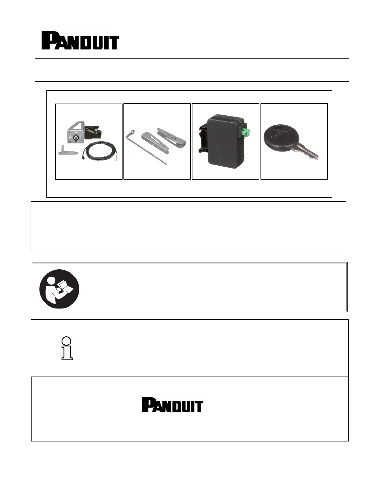
The VeriSafe Access Control Kit, inst alled with the VeriSafe Abse nce of Volta ge Te ster, provide s an added layer
to the equipment.
VS-ACK-CPWR
VS-ACK-EXT
VS-ACK-BATTERY
VS-ACK-KEY
Instruction Manual
Models: VS-ACK-CPWR, VS-ACK-EXT, VS-ACK-KEY & VS-ACK-BATTERY
Rev: 01; 1-2020
of protection by preventing enclo sure doors from being opened until absence o f voltage is confirmed. Before
entering the electrical cabinet, personnel will use the VeriSafe Absence of Volt ag e T este r to test for absence of
voltage. The VeriSafe Access Control Kit will receive a signal from the VeriSafe Absence of Voltage Tester when
the absence of voltage is confirmed. The rotary latch will unlock, releasing the enclosure door and allow access
TO REDUCE THE RISK OF INJURY, USER
MUST READ INSTRUCTION MANUAL
NOTE: In the interest of higher quality and value, Panduit products are
continually being improved and updated. Consequently, pictures may vary
from the enclosed product.
North America Tech Support:
techsupport@panduit.com
Tel: 1-866-405-6654
EU Tech Support :
emeatoolservicecenter
@panduit.com
Tel: +31-546-580-452
Fax: +31-546-580-441
NOTE: Updates to this Instruction Manual may be available. Check
www.panduit.com for the latest version of this manual.
Asia Pacific Tech Support:
TechSupportAP@ panduit.com
Telephone:
Korea: 02-21827300
www.panduit.com
Singapore: 1-800-Panduit (7263848)
Australia: 1-800-Panduit (7263848)
Page 2
© Panduit Corp. 2019
Warning: Do not use this product outside of the specified performance and environmental limits.
Failure to comply with these specifications could result in product failure, personal injury, or death.
Standards
Applications
Degree of Protection*
For Flat Surface Mounting in a TYPE (UL, NEMA and CSA) 1, 12, 4, IP65 Enclosure
Environment
Operating Temperature
-25°C to 60°C (-13°F to 140°F)
Storage Temperature
-45°C to 85°C (-50°F to 185°F)
Humidity
5 to 90% non-condensing; Rated 80% at 40°C, decreasing linearly to 50% at 60°C
VS-ACK-BATTERY
Type
Industrial 9V Metal Lithium (qty: 2)
INSTRUCTION MANUAL VeriSafe ACK
Safety Information
This manual contains information and warnings which must be follow ed to ensure safe operation of the Access Control Kit. If the
Access Control Kit is not used as described in this manual, the safety features of the Access Control Kit might be imp aire d. The
Access Control Kit is designed for use with the VeriSafe AVT. Reference the VeriSafe AVT instruction manual for critical safety
information, installation and operating instructions. Failure to comply with the warnings and information in this manual
could result in product failure, electrical shock, severe injury or death.
Warning:
•
Always de-energize power before accessing an electrical enclosure.
•
Always follow safety and lockout/tagout procedures when working on or near electrical systems and equipment.
•
Use of the Access Control Kit does not replace lockout/tagout procedures. The Access Contr ol Kit is intended to be used in
conjuncti on with the VeriSafe AVT and the lockout/tagout processes.
•
Use proper personal protective equipment (PPE) when working around sources of hazardous electrical energy.
•
Do not use this product outside of the specified performance and environmental lim its. Failure to comply with these
specifications could result in product failure, personal injury or death.
•
This product must be installed by a qualified electrical worker familiar with local and national electrical codes.
•
Always comply with local installation codes and standards.
•
The VS-ACK-BATTERY product uses a lithi um battery that is a fire, explosion and s evere bur n hazard. Do not crush, rechar ge,
disassemble or heat above 85° C, incinerate, or expose contents to water.
•
Use only the included Wire Harness or approved replacement harness to connect the Rotary Latch and VeriSafe AVT.
Technical Specifications
RoHS Restriction of hazardous substances
Electrical System For use in 1 and 3-phase AC or DC systems
*Degree of protection specified is related to the Latch Cam only. To meet the TYPE (UL, NEMA and CSA) 1, 12, 4, IP65 requirements, mount on
a flat surface of an enclosure meeting the appropriate TYPE rating. Verify that the Sealing Washer is clean and properly seated onto the Latch
Cam to ensure proper sealing.
Classification Non-Rechargeable
Designation ANSI-1604LC
Operating Temperature -20°C to 60°C (-4°F to 140°F)
Mounting Type DIN Rail or Surface Mount
Estimated Capacity 1 cycle per week for 10 years
1003190 R00 Page: 1 of 7 10-2019
Page 3
© Panduit Corp. 2019
INSTRUCTION MANUAL VeriSafe ACK
VS-ACK-CPWR Install Instructions
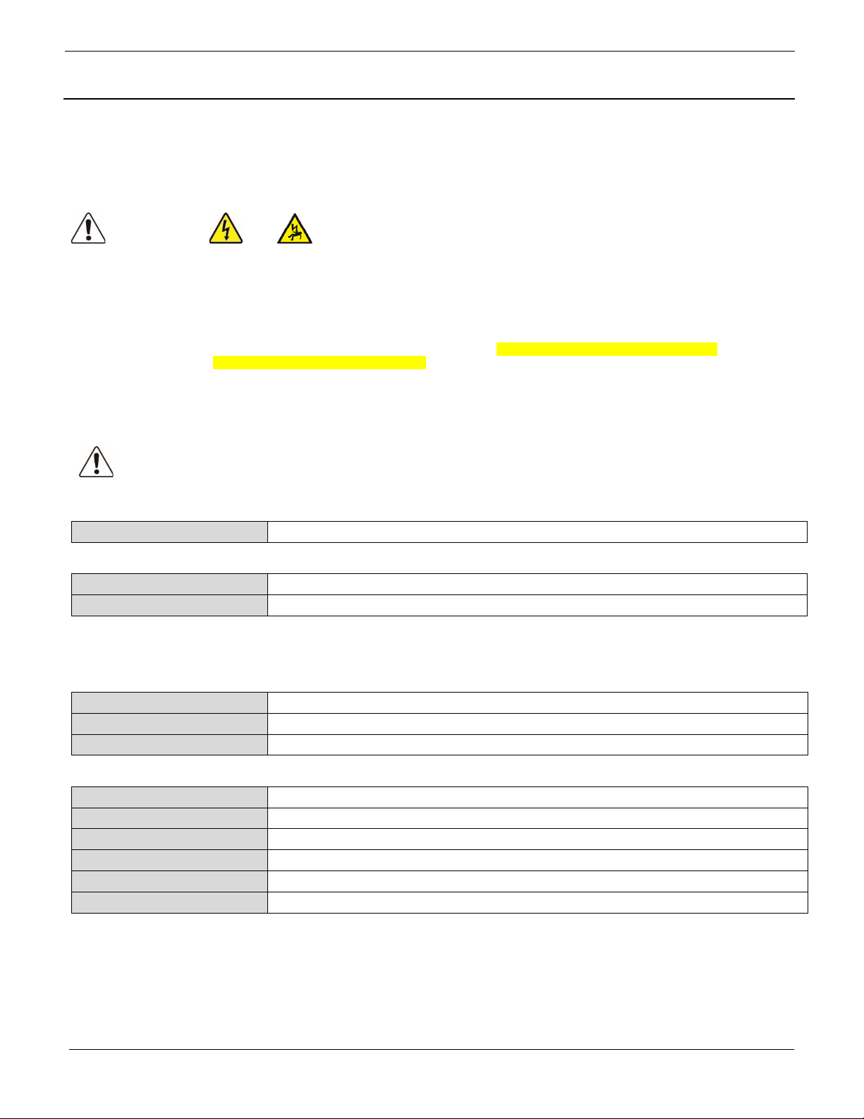
Figure 1 - Componen ts of the VeriSaf e A cces s C ontr ol Kit – Control Power (VS-ACK-CPWR)
Figure 2 – Quick Assembly Guide 1 – Contr ol Powe r (VS-ACK-CPWR)
1003190 R00 Page: 2 of 7 10-2019
Page 4

© Panduit Corp. 2019
The Enclosure Bracket and Cam Latch are designed for
INSTRUCTION MANUAL VeriSafe ACK
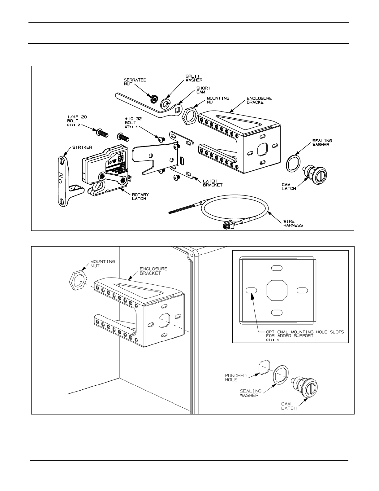
Figure 3 – Quick Assembly Guide 2 – Contr ol Powe r (VS-ACK-CPWR)
use with a standard Double “D” punch.
Greenlee Punch Number: 61095
Figure 4 – Punch Knockout
1003190 R00 Page: 3 of 7 10-2019
Figure 5 – Wiring Schematic
Page 5
© Panduit Corp. 2019
Left Side Mount
Right Side Mount
•
The ACK must be installed correctly and grounded as described in this Instructio n Manual to oper ate prope rl y.
Always de-energize power before accessing an electrical enclosure.
Use proper personal protective equipment (PPE) when working around sources of hazardous electrical energy.
Always follow safety and lockout/tagout procedures when working on or near electrical systems and equipment.
Do not use this product outside of the specified performance and environmental limits.
Always comply with local installation codes and standards.
1. Locate position for the knockout hole by
be vertical (see figure 4 ).
2. Insert the Cam Latch into the knockout
3. Install the Enclosure Bracket onto the Cam
4. Install Cam onto Cam Latch with
5. Install the Rotary Latch to the Latch
6. Place supplied Two-Sided tape onto the
Installation Instructions
Warning:
•
•
•
•
•
INSTRUCTION MANUAL VeriSafe ACK
measuring 5-1/8 inches from the surface
where the cabinet door seats to the
desired mounting location on the side of
the cabinet (when installing the VS-ACKEXT kit refer to VS-ACK-EXT install
instructions for proper hole distanc e). Use
Double “D” knockout (not included) to
punch hole. Ensure that the punch is
positioned properly. The punch flats shall
supplied Split Washer and Serrated Nut
(see figure 3).
1003190 R00 Page: 4 of 7 10-2019
hole. Ensure that the Sealing Washer is
properly seated between the panel wall
and the Cam Latch (see figure 2).
Latch and hand tighten the Mounting Nut.
Check that the bracket is level and finish
tightening the Mounting Nut to 88 IN*LB
(10 N*m) max (see figure 2).
Bracket with supplied ¼”-20 Bolts (2) and
secure to Enclosure Bracket with supplied
#10-32 Bolts (4). Ensure that the Rotary
Latch is installed so the Cam rotates and
engages the Override Latch (left side
mount shown) (see figure 3).
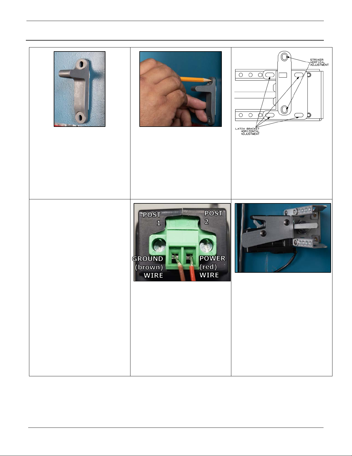
back side of the Striker and install Striker
onto the Rotary Latch.
Page 6
© Panduit Corp. 2019
7. Close the cabinet door and lock into
8. Mark the mounting locations for the
9. Close the cabinet door and ensure that
INSTRUCTION MANUAL VeriSafe ACK
position. Engage the mechanical override
on the ACK and open the cabinet door.
The Striker will be positioned onto the
inside of the cabinet door.
10. IF USING CONTROL POWER
OPTION:
Connect the wires of the Wire Harnes s to
the VeriSafe Absense of Voltage Tester
(AVT) and the desired power source per
the wiring schematic.
POWER SOURCE REQUIREMENTS
• 12-24 VDC
• Operating current to be less than
500mA at 12 VDC
Striker as it is positioned on the cabinet
door. Remove Striker from door and
remove all the Two-Sided tape from the
door and Striker. Mount Striker to the
cabinet door using the proper NEMA rated
mounting hardware (not included).
11. VS-ACK-BATTERY POWER
OPTION:
Connect the wires of the Wire Harnes s to
the VeriSafe Absense of Voltage Tester
(AVT) and the VS-ACK-BATTERY kit.
• Ground (brown) wire to post 1
• Power (red) wire to post 2
the ACK is working properly. If needed
adjust the Striker or Latch Bracket to
eliminate any interference. The
mounting holes for both the Striker and
Latch Bracket are slotted for adjustment.
12. Install the Wire Harness to the Rotary
Latch.
1003190 R00 Page: 5 of 7 10-2019
Page 7
© Panduit Corp. 2019
INSTRUCTION MANUAL VeriSafe ACK
VS-ACK-EXT Install Instructions
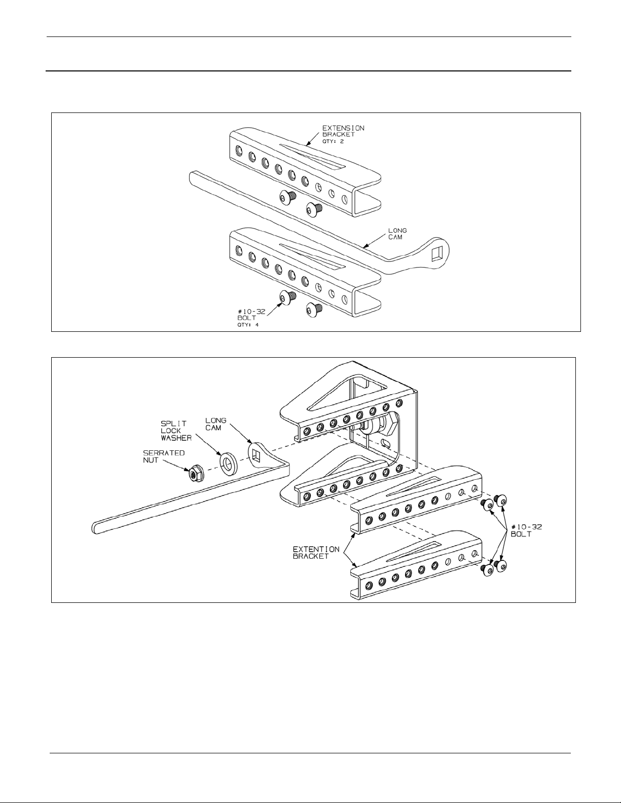
Figure 6 - Components of the VeriSafe Access Control Kit – Extension Kit (VS-ACK-EXT)
Figure 7 – Quick Assembly Guide – Extension Kit (VS-ACK-EXT)
Installation Instructions
In the case of the cabinet having a door lip greater that 5-1/8 inches the VS-ACK-EXT kit will need to be installed onto the VS-ACK-CPWR kit.
• Locate position for the knockout hole by measuring 5-13/64 inches from the surface where the cabinet door seats to the desired
mounting location on the side of the cabinet.
• Replace Short Cam (supplied in VS-ACK-CPWR kit) with the Long Cam (supplied in VS-ACK-EXT kit).
• Install the Extention Brackets onto the Enclosure Bracket with supplied #10-32 Bolts (4). See figure 7.
1003190 R00 Page: 6 of 7 10-2019
Page 8

© Panduit Corp. 2019
Commissioning Checklist
INSTRUCTION MANUAL VeriSafe ACK
□ Visually inspect the ACK:
• Mechanical Overrid e : Ver ify that t h e C am engages the overri de latch on the Rot ary Latch.
• Striker: Verify that the S t r iker is properly aligned with th e Ro t ary Latch.
• Enclosure Bracket: Ensure that the Mounting Nut is tightened to 88 IN*LB (10 N*m) max and that the
Enclosure Bracket does not rota t e. If rot ation occurs, there are four (4) #10-3 2 clearance slots w h ere
additional bolts can be added to the Enclosure bracket.
• Wire Harness: Verify that the cable is locked into place on the Rotary Latch. Also verify that the wire leads
are securely t er m i n ated to the AVT a n d t h e power source by g ently pulling on each wire lead.
□ Record changes to panel documentation.
□ Verify that the mechanical override is properly working before closing the panel door.
□ Close panel door and secure.
Warning
electric shock, use proper personal protective equipment when working on or near electrical hazards.
: Always follow your company’s safety procedures when energizing equipment. To avoid
□ Energize the system.
□ Verify that the red Voltage Presence Indicators are illuminated.
□ Verify that entry into t he cabinet is prohibited by the Access Control Kit.
□ De-energize the system.
□ Press the Test Button on the AVT Indicator Module to begin the absence of voltage test. Look for the
yellow Caution Indicator to flash and then the green Absence of Voltage Indicator should illuminate.
□ Verify that entry is allowed into the cabinet.
Maintenance
Visual Inspection
• Periodically inspect the Access Control Kit an d re place any damaged parts, cables or terminations.
• Inspect the Access Control Kit Wire Harness to ensure it is locked into place on the Rotary Latch and does
not show signs of damage.
• The Procedure described in the Commissioning Checklist can be performed at any time.
1003190 R00 Page: 7 of 7 10-2019
 Loading...