

Page 1
PTR3E
Thermal Transfer Printer
Operator and Technical
Reference Manual
Page 2

Panduit Corp.
Identification Products Division
1819 Atlanta Hwy.
Cumming, GA 30040-1069
Phone: 888-506-5400
Fax: 770-889-9264
Copyright © Panduit Corp. 2001. All Rights Reserved
Panduit PTR3E
Page 3

This manual will guide you step by step in the set-up, operation, and
troubleshooting of the PTR3E Printer. If you have problems not covered
call Technical Support at 1-888-506-5400, ext. 7470.
SAFETY PRACTICES
The following general safety practices supplement the specific warnings
and cautions elsewhere in this manual. They are recommended
precautions that must be understood and applied during the operation
and maintenance of the equipment covered herein.
DO NOT OPERATE IN AN EXPLOSIVE ATMOSPHERE
Do not operate the product in the presence of flammable gases or fumes.
Operation of any electrical equipment in such an environment
constitutes a definite safety hazard.
DO NOT OPERATE IN WET OR DAMP AREAS
Do not operate the product in wet or damp areas. Operation of any
electrical equipment in such an environment constitutes a definite safety
hazard.
DO NOT SUBSTITUTE PARTS OR MODIFY EQUIPMENT
Because of the danger of introducing additional hazards, do not install
substitute parts or perform an unauthorized modification to the
equipment. The proper components for service and repair may be
obtained from Panduit Corp., Labeling Systems Department,
1-888-506-5400, ext. 7470. The product may also be returned for service
and repair by calling the above number and requesting a Tracking
Number. Please provide your company name, contact name, address,
telephone number and serial number of the printer (and P.O. Number if
out of warranty) when requesting the Tracking Number. After Tracking
Number is received the printer should be returned to :
Panduit Corp.
1819 Atlanta Highway
Cumming, GA 30040-1069
Attention: Labeling Systems Repair Department
WARNING
When the printer has been in use for a long time, the print head may
become hot. DO NOT touch the print head with bare hands.
Page 4

INFORMATION TO USER
NOTE: This equipment has been tested and found to comply
with the limits for a Class A digital device, pursuant to Part 15 of
FCC Rules. These limits are designed to provide reasonable
protection against harmful interference when the equipment is
operated in a commercial environment. This equipment
generates, uses, and can radiate radio frequency energy and, if
not installed and used in accordance with the instruction
manual, may cause harmful interference to radio
communications. Operation of this equipment in a residential
area is likely to cause interference in which case the user will be
required to correct the interference at his own expense.
WARRANTY INFORMATION
Our products are warranted to be free from defects in material and
workmanship at the time of sale but our obligation under this warranty is
limited to the replacement of any product proved to be defective within 6
months (for product) or 90 days (for printers) from the date of delivery.
Please remember to fill out the enclosed warranty card and return it to
Panduit. Printer warranty is void if Panduit printers are modified,
altered, or misused in any way. Use of Panduit printers with any product
other than the specified Panduit products for which the printer was
designed, constitutes misuse. Before using, user shall determine the
suitability of the product for his intended use and user assumes all risk
and liability whatsoever in connection therewith.
This warranty is made in lieu of and excludes all other warranties,
expressed or implied. THE IMPLIED WARRANTIES OF
MERCHANTABILITY AND FITNESS FOR A PARTICULAR USE ARE
SPECIFICALLY EXCLUDED. Neither seller nor manufacturer shall be
liable for any injury, loss or damage, whether direct or consequential,
arising out of the use of, or the inability to use the product.
The information contained in this literature is based on our experience to
date and is believed to be reliable. It is intended as a guide for use by
persons having technical skill at their own discretion and risk. We do not
guarantee favorable results or assume any liability in connection with its
use. Dimensions contained herein are for reference purposes only. For
specific dimensional requirements consult the factory. This publication
is not taken as a license to operate under, or a recommendation to
infringe upon any existing patents. This supersedes and voids all
previous literature, etc.
Page 5

PTR3E OPERATOR MANUAL
The PTR3E Operator Manual contains basic information about the printer such
as setup, installation, cleaning and maintenance. It also contains complete
instructions on how to use the operator panel to configure the printer. The
following is a brief description of each section in this manual.
SECTION 1. PRINTER OVERVIEW
This section contains a discussion of the printer specifications and
optional features.
SECTION 2. INSTALLATION
This section contains instructions on how to unpack and set up the
printer, load the labels and ribbon.
SECTION 3. CONFIGURATION
This section contains instructions on how to configure the printer using
the DIP switches and the LCD / Menu / Control Panel.
PREFACE
SECTION 4. CLEANING AND MAINTENANCE
This section contains instructions on how to clean and maintain the
printer.
SECTION 5. INTERFACE SPECIFICATIONS
This section contains the printer’s interface specifications.
SECTION 6. TROUBLESHOOTING
This section contains troubleshooting procedures to follow in the event
you have printer problems.
i
Page 6

Preface
TABLE OF CONTENTS
SECTION 1. PRINTER OVERVIEW
Introduction ..............................1
General Printer Specifications ....................2-3
Character Fonts ............................4
BarCodes...............................5
Physical ................................6
SECTION 2. INSTALLATION
Introduction ..............................7
Unpacking and Parts Identification .................8-9
Setting Up the Printer ........................9-10
LoadingLabels............................11-13
LoadingtheRibbon..........................14-15
Operator Panel ............................16-17
Rear Panel...............................18
Switches and Sensors .........................19
Label Sensor Adjustment .......................20
SECTION 3. CONFIGURATION
Printer DIP Switch Configuration ..................21-25
PrinterAdjustments .........................26-35
Potentiometer Adjustments .....................35-36
DisplayCounterValues........................37
SECTION 4. CLEANING AND MAINTENANCE
Introduction ..............................39
Procedures...............................39-45
Adjusting the Print Quality ...................39-40
Darkness............................39
PrintSpeed ..........................40
Cleaning the Print Head, Platen and Rollers ..........41-42
Cleaning the Sensors .......................42
ReplacingthePrintHead.....................43-44
ReplacingtheFuse........................45
ii
Page 7

SECTION 5. INTERFACE SPECIFICATIONS
IEEE1284 Parallel Interface .....................47
RS232C Serial Interface .......................48
SECTION 6. TROUBLESHOOTING
Initial Checklist ............................49
Using the IEEE1284 (Parallel) Interface ..............49-50
Using the RS232C (Serial) Interface .................50
Error Signals .............................51
Preface
iii
Page 8

Page 9

INTRODUCTION
The Panduit PTR3E Thermal Transfer Printer is a complete, high-performance
on-site labeling system. All printer parameters are user programmable using the
front panel controls and the DIP switches. All popular bar codes and 14
human-readable fonts, including a vector font and two raster fonts, reside in
memory providing literally thousands of type styles and sizes.
The Operator Manual will help you understand the basic operations of the
printer such as setup, installation, configuration, cleaning and maintenance.
The PTR3E has a resolution of 203 dpi and can print labels up to four inches
wide.
The following general information is presented in this section:
SECTION 1.
PRINTER OVERVIEW
• General Printer Specifications
• Character Fonts
• Bar Codes
• Physical Specifications
1
Page 10
Section 1. Printer Overview
GENERAL PRINTER SPECIFICATIONS
SPECIFICATION PTR3E
PRINT
Method Direct or Thermal Transfer
Speed (User Selectable) 2 to 10 ips
50 to 250 mm/s
Print Module (Dot Size) .0049 in.
.125 mm
Resolution 203 dpi
8 dpmm
Maximum Print Width 4.1 in.
104 mm
Maximum Print Length 49.2 in.
1249 mm
MEDIA
Minimum Width .87 in. (22 mm)
Minimum Length .63 in. (16 mm)
Maximum Width 5.0 in. (128 mm)
Type Die Cut Labels, Fan-Fold or Continuous
Maximum Caliper .010 in. (.25 mm)
Roll OD (max) 8.6 in. (218 mm), Face-Out Wind
Core ID (min) 1.5 in. (38 mm)
Core ID (Recommended) 3 in. (76 mm)
SENSING
See-Thru for labels Movable
Reflective Eye-Mark Movable
Continuous Form Sensor not used
RIBBON
Maximum Width 4.4 in. (111 mm)
Maximum Length 1475 ft. (450 m)
Thickness 4.5 micron, Ink-In Wind
All specifications subject to change without notice.
2
Page 11
Section 1. Printer Overview
SPECIFICATION PTR3E
CONTROLS AND SIGNALS
On-Line Green LED
Power Green LED
Label Red LED
Ribbon Red LED
Error Red LED
LCD Panel 2 Line x 16 Character
On/Off-Line Switch Front Panel
Label Feed Switch Front Panel
Power On/Off Switch Front Panel
POTENTIOMETER ADJUSTMENTS
Print Darkness Front Panel
Pitch Front Panel
Offset Front Panel
Display Front Panel
INTERFACE CONNECTIONS
Parallel* IEEE1284 Compatible Standard
Serial RS232C (9600 to 57600 bps) Standard
RS422/485 (9600 to 57600 bps) Optional
Serial Protocol Hardware Flow Control (Ready/Busy)
Software Flow Control (X-On/X-Off)
Bi-directional Status
Data Transmission ASCII Format
PROCESSING
CPU 32 Bit RISC
Flash ROM 2 MB
SDRAM 16 MB
Receive Buffer 2.95 MB
All specifications subject to change without notice.
* PTR3E comes standard with parallel port. Contact factory if serial port is required.
3
Page 12
Section 1. Printer Overview
CHARACTER FONTS
SPECIFICATION PTR3E
MATRIX FONTS
U Font (5 dots W x 9 dots H)
S Font (8 dots W x 15 dots H)
M Font (13 dots W x 20 dots H)
XU Font (5 dots W x 9 dots H) Helvetica
XS Font (17 dots W x 17 dots H) Univers Condensed Bold
XM Font (24 dots W x 24 dots H) Univers Condensed Bold
OA Font (15 dots W x 22 dots H) OCR-A
OB Font (20 dots W x 24 dots H) OCR-B
AUTO SMOOTHING FONTS
WB WB Font (18 dots W x 30 dots H)
WL WL Font (28 dot W x 52 dots H)
XB XB Font (48 dots W x 48 dots H) Univers Condensed Bold
XL XL Font (48 dot W x 48 dots H) Sans Serif
VECTOR FONT
Proportional or Fixed Spacing
Font Size 50 x 50 dots to 999 x 999 dots
Helvetica, 10 Font Variations
AGFARASTER FONTS
Font A CG Times, 8 to 72 pt
Font B CG Triumvirate, 8 to 72 pt
DOWNLOADABLE FONTS
Bit Mapped TrueTypeFonts with Utility Program
CHARACTER CONTROL
Expansion up to 12X in either the X or Y coordinates
Character Pitch control
Line Space control
Journal Print facility
0°, 90°, 180° and 270° Rotation
All specifications subject to change without notice.
4
Page 13
Section 1. Printer Overview
BAR CODES
SPECIFICATION PTR3E
SYMBOLOGIES
Bookland (UPC/EAN Supplemental)
EAN-8, EAN-13
CODABAR
Code 39
Code 93
Code 128
Interleaved 2 of 5
Industrial 2 of 5
Matrix 2 of 5
MSI
POSTNET
UCC/EAN-128
UPC-A and UPC-E
Data Matrix
Maxicode
PDF417
Micro PDF
Truncated PDF
QR Code
Ratios 1:2, 1:3, 2:5 User definable bar widths
Bar Height 4 to 600 dots, User programmable
Rotation 0°, 90°, 180° and 270°
OTHER FEATURES
Sequential Numbering Sequential numbering of both numerics and bar codes
Custom Characters RAM storage for special characters
Graphics Full dot addressable graphics, .BMP or .PCX formats
Form Overlay Form overlay for high-speed editing of complex formats.
All specifications subject to change without notice.
5
Page 14
Section 1. Printer Overview
PHYSICAL
SPECIFICATION PTR3E
DIMENSIONS
Wide 10.4 in. (265 mm)
Deep 17.1 in. (435 mm)
High 13.4 in. (341 mm)
WEIGHT 39.6 lbs (18 Kg)
POWER REQUIREMENTS
Voltage
Power Consumption 50W Idle
ENVIRONMENTAL
Operating Temperature 41° to 104°F (5° to 40°C)
Storage Temperature -0° to 104°F (-20° to 40°C)
Operating Humidity 15-85 % RH, non-condensing
Storage Humidity Max 90% RH, non-condensing
Electrostatic Discharge 8KV
REGULATORY APPROVALS
Safety UL, CSA, TUV, CE
RFI/EMI FCC Class A
All specifications subject to change without notice.
100 - 115 V , ±10 % (Default Setting)
220V , ±10 %
50/60 Hz, ±1%
130W Operating
6
Page 15

INTRODUCTION
This section will assist you in taking the PTR3E from the shipping container to
the application environment.
The following information is provided in this section:
SECTION 2.
INSTALLATION
Unpacking and Parts Identification
•
Setting Up the Printer
•
Loading Labels
•
Loading the Ribbon
•
• Operator Panel
• Rear Panel
• Switches and Sensors
• Label Sensor Adjustment
7
Page 16
Section 2. Installation
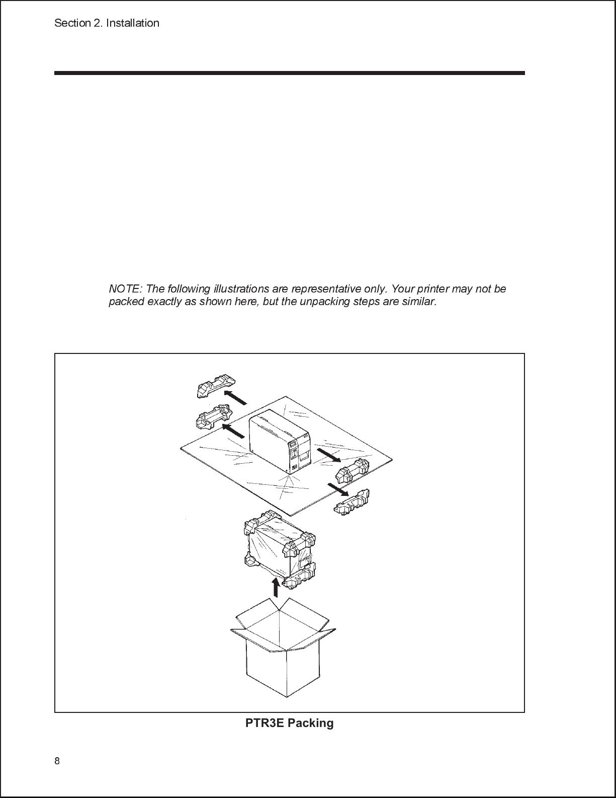
UNPACKING AND PARTS IDENTIFICATION
Consider the following when unpacking the printer:
The box should stay right-side up.
•
Lift the printer out of the box carefully.
•
Remove the plastic covering from the printer.
•
Remove the accessory items from their protective containers.
•
If the printer has been stored in a cold environment, allow it to reach
•
room temperature before powering it on.
Set the printer on a solid, flat surface. Inspect the shipping container
•
and printer for any signs of damage that may have occurred during
shipping.
NOTE: The following illustrations are representative only. Your printer may not be
packed exactly as shown here, but the unpacking steps are similar.
PTR3E Packing
8
Page 17
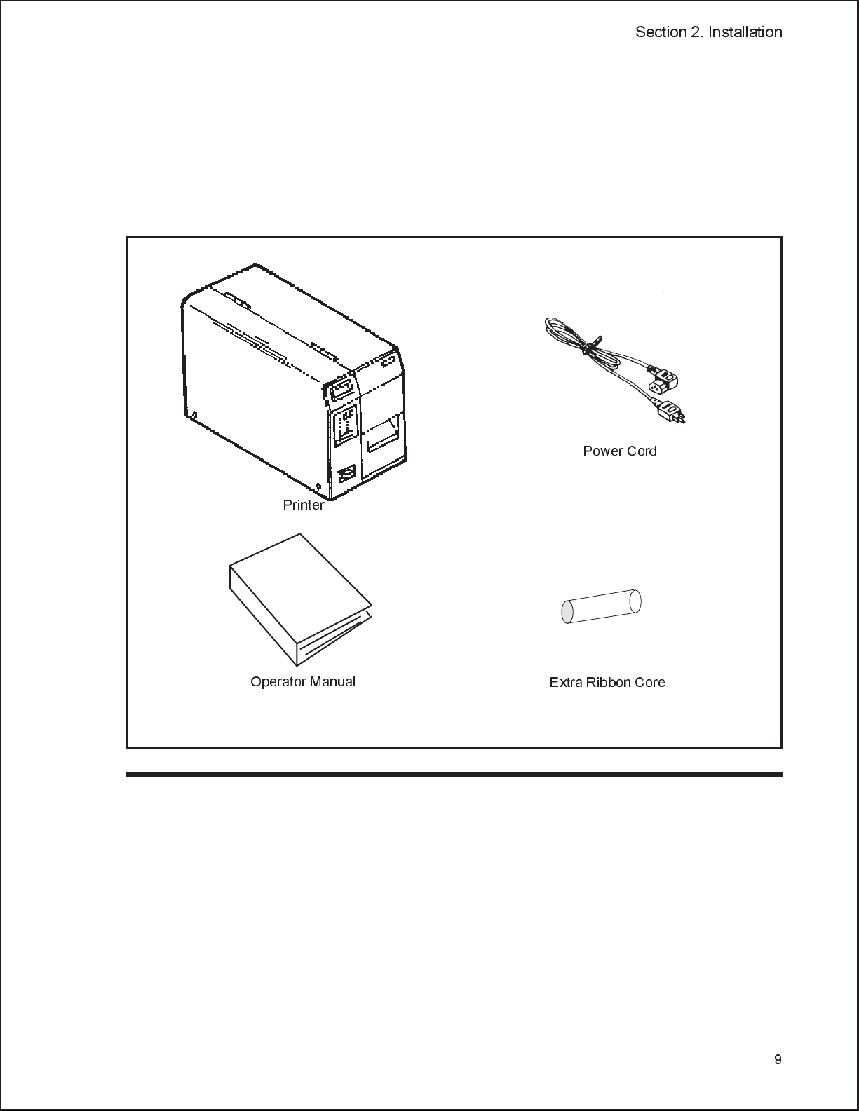
Verify that you have the following materials when unpacking:
Printer
•
Power Cord
•
Extra Ribbon Core
•
Operator and Technical Reference Manual
•
Section 2. Installation
Printer
Operator Manual
SETTING UP THE PRINTER
Consider the following when setting up the printer:
•
Locate a solid flat surface with adequate room to set the printer. Make
sure there is enough room at the top and right-hand (facing the printer)
side to provide clearance for the label access door to swing open.
Power Cord
Extra Ribbon Core
•
The location should be near the host computer or terminal. The maximum
distance for RS232 cables is 35 feet and six feet for IEEE1284 Parallel
cables. Cables can be purchased locally, and their configuration will
depend upon the host system being used. An IEEE1284 compliant cable
must be used to realize the full throughput potential of the printer.
9
Page 18

Section 2. Installation
Top Access
Door
LCD
Display
DIP Switch
Cover
Power Switch
Ribbon Rewind
Spindle
Ribbon Supply
Spindle
Side Access
Door
Label Roll Retainer
Label Supply Spindle
Label Guide
Print Head
Head Latch
Platen
10
Page 19
LOADING LABELS
Follow these steps to properly load labels into
the PTR3E:
Section 2. Installation
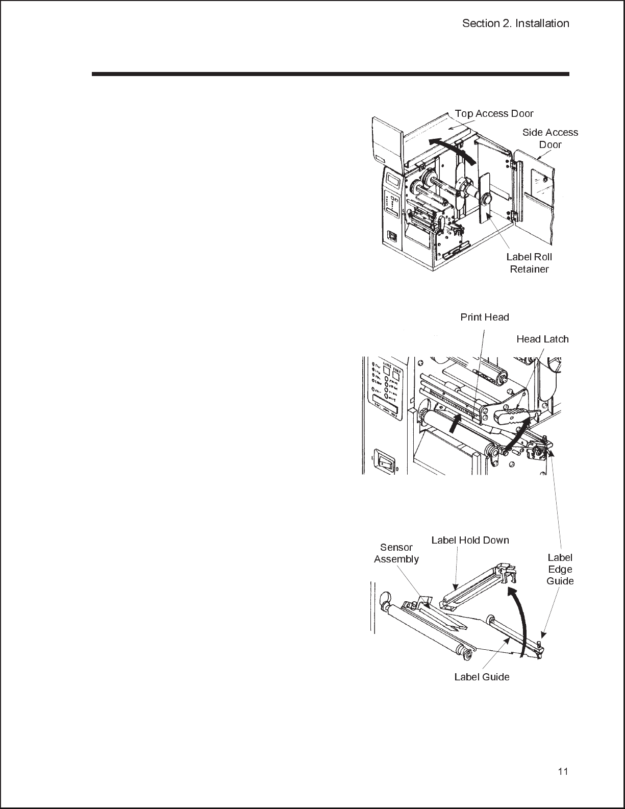
Top Access Door
1. Open the Top Access Door by
swinging it up and to the left. Open
the Side Access Door by
swinging it to the rear of the
printer.
2. Open the Print Head Assembly
by pushing the Head Latch
toward the rear of the printer. The
Print Head Assembly is
spring-loaded and will
automatically open as soon as the
Head Latch is disengaged.
Side Access
Door
Label Roll
Retainer
Print Head
Head Latch
3. Loosen the Label Edge Guide
and push it to the outside of the
printer to give the maximum label
width.
4. Remove the Label Roll
Retainer.
Sensor
Assembly
Label Hold Down
Label
Edge
Guide
Label Guide
11
Page 20
Section 2. Installation
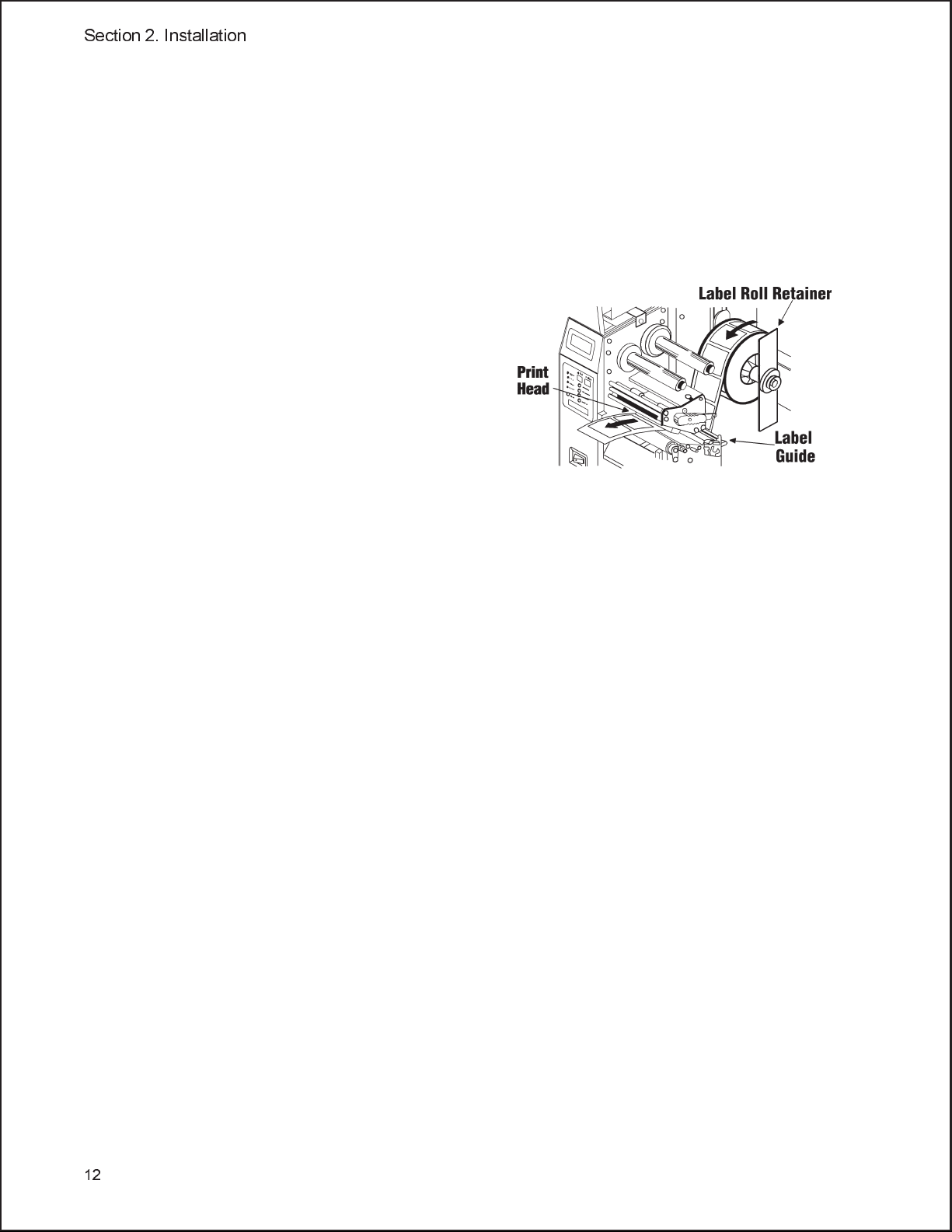
5. If using roll labels (or tags), load the roll onto the Label Supply Spindle so that
the printing side of the labels faces upwards as it unwinds from the roll. Push
the roll all the way to the inside of the printer and push the Label Roll
Retainer snugly against the outside of the label roll.
6. If using fanfold labels set them on a flat surface behind the printer. Pass the
labels (printing side up) through the slot in the rear of the printer.
7. Make sure the labels are routed
under the Label Guide and
through the Sensor Assembly.
8. Open the Label Hold-Down by
squeezing the green tab and the
release tab together. The Label
Hold Down is spring loaded and
will open automatically when the
latch is disengaged. Feed the labels
under the Label Guide, under the
Label Hold Down, through the
Sensor Assembly and out the front
of the printer.
9. Inspect the label routing and verify that the path matches that illustrated in the
Label Loading diagram. Set the Adjustable Label Guide to keep the labels
against the inside of the printer.
10. Close the Label Hold-Down by pushing downward on the green tab until it
latches closed.
12
Page 21
Section 2. Installation
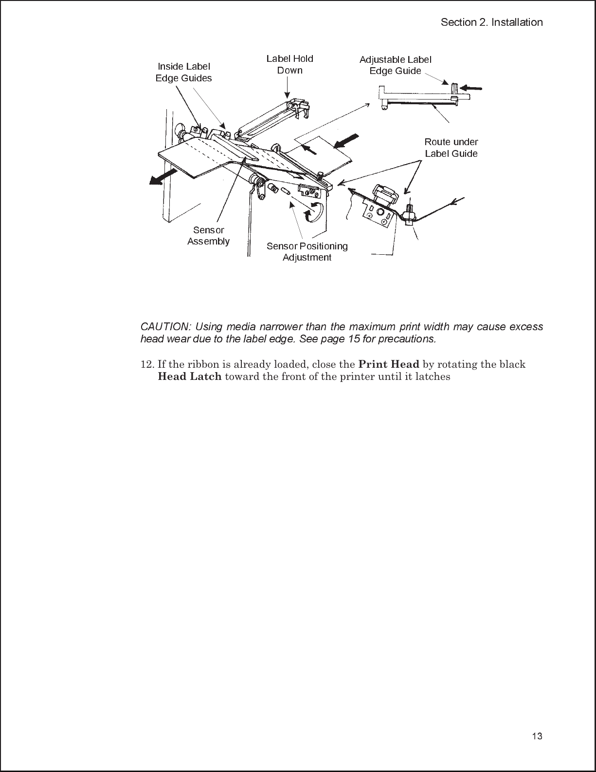
Inside Label
Edge Guides
Sensor
Assembly
Label Hold
Down
Sensor Positioning
Adjustment
Adjustable Label
Edge Guide
Route under
Label Guide
11. Adjust the outside Label Edge Guide until it touches the outside edge of the
label and tighten the thumb screw. Make sure the labels are also touching the
inside edge guides.
CAUTION: Using media narrower than the maximum print width may cause excess
head wear due to the label edge. See page 15 for precautions.
12. If the ribbon is already loaded, close the Print Head by rotating the black
Head Latch toward the front of the printer until it latches closed.
13. If the ribbon is not loaded, see the following description for loading
instructions.
14. Close both Access Doors.
13
Page 22
Section 2. Installation
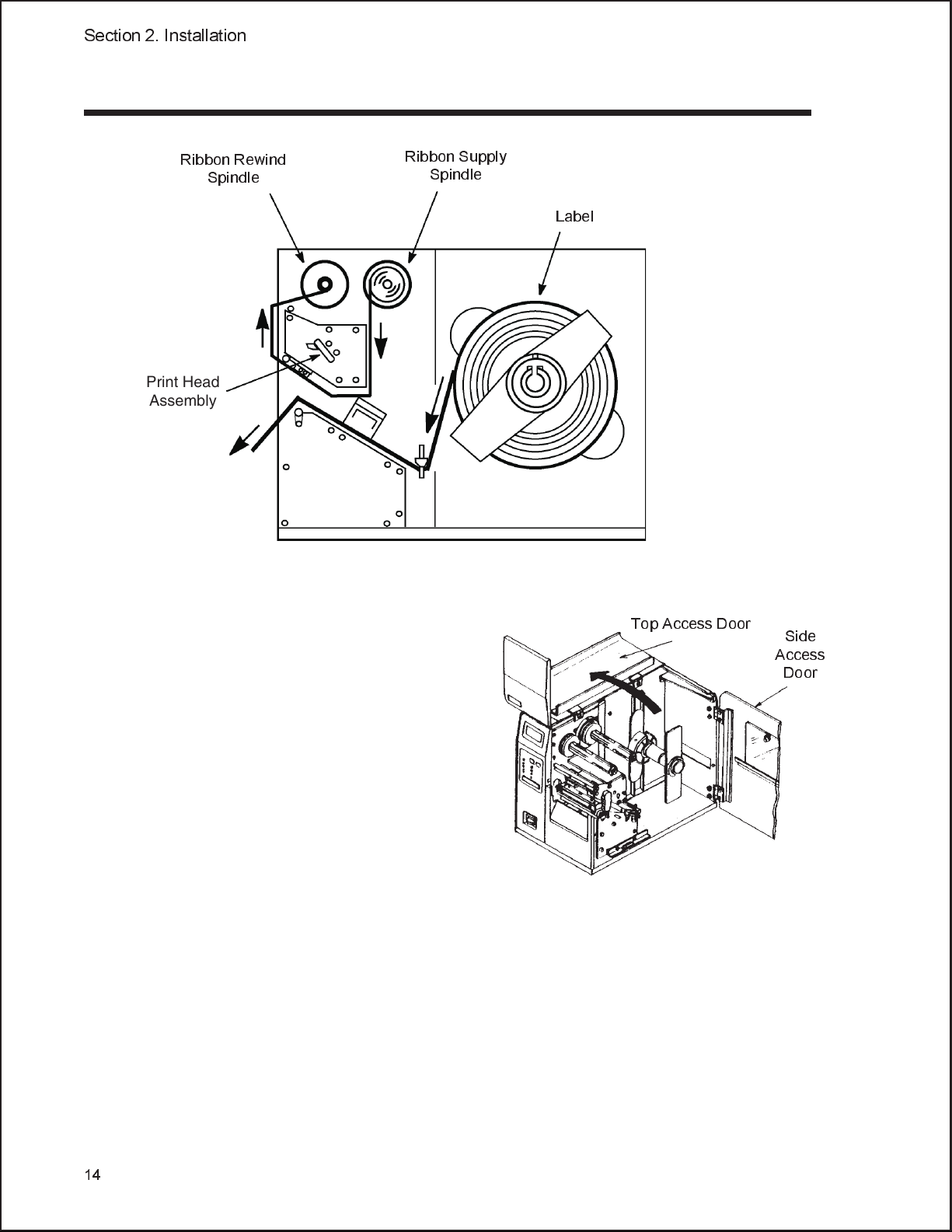
LOADING THE RIBBON
Ribbon Rewind
Print Head
Assembly
Spindle
Ribbon Supply
Spindle
Label
1. Open the Top Access Door by
swinging it up and to the left and
the Side Access Door by
swinging it toward the rear of the
Top Access Door
Side
Access
Door
printer.
2. Open the Print Head by rotating
the Head Latch toward the rear
of the printer. The Print Head is
spring-loaded and will
automatically open as soon as the
Head Latch is disengaged.
3. Locate the Extra Ribbon Core
supplied with the printer. Place
the core on the Ribbon Rewind Spindle, pushing it all the way to the inside of
the spindle. Note that the new empty core of each subsequent roll becomes the next
rewind core.
4. Load the ribbon onto the Ribbon Supply Spindle, also pushing it all the way
to the inside of the spindle. The dull side of the ribbon should be facing down as it
travels through the Print Head Assembly.
14
5. Feed the leader portion of the ribbon through the Print Head Assembly and
up to the Ribbon Rewind Spindle following the routing shown in the
diagram.
Page 23
Section 2. Installation
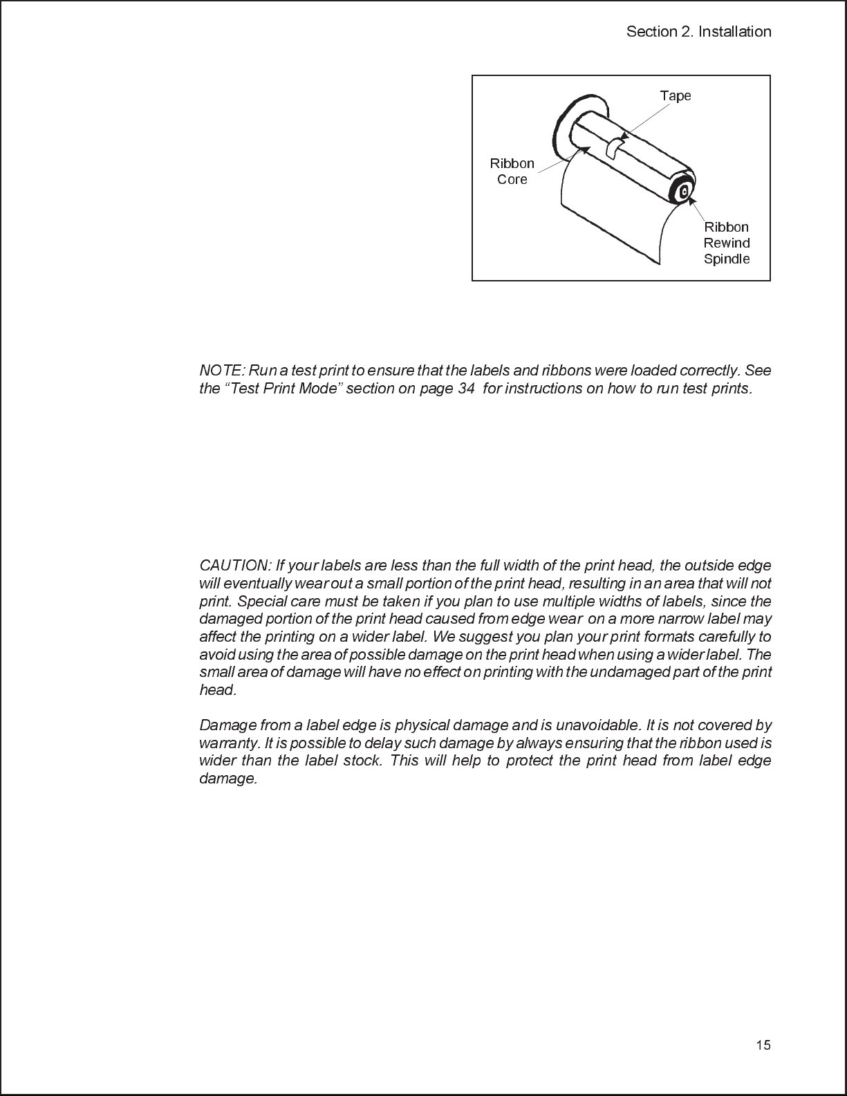
6. Load the ribbon behind and over
the top of the Ribbon Rewind
Tape
Spindle and tape it to the Extra
Ribbon Core. Make sure it
matches the ribbon path shown in
the diagram.
Ribbon
Core
7. Manually turn the Rewind
Spindle to wrap the ribbon onto
the core one to two turns to secure
it.
Ribbon
Rewind
Spindle
8. If the labels are already loaded,
close the Print Head Assembly by pushing downward on the green tab until it
latches closed.
NOTE: Run a test print to ensure that the labels and ribbons were loaded correctly. See
the Test Print Mode section on page 34 for instructions on how to run test prints.
CAUTION: If your labels are less than the full width of the print head, the outside edge
will eventually wear out a small portion of the print head, resulting in an area that will not
print. Special care must be taken if you plan to use multiple widths of labels, since the
damaged portion of the print head caused from edge wear on a more narrow label may
affect the printing on a wider label. We suggest you plan your print formats carefully to
avoid using the area of possible damage on the print head when using a wider label. The
small area of damage will have no effect on printing with the undamaged part of the print
head.
Damage from a label edge is physical damage and is unavoidable. It is not covered by
warranty. It is possible to delay such damage by always ensuring that the ribbon used is
wider than the label stock. This will help to protect the print head from label edge
damage.
15
Page 24
Section 2. Installation
OPERATOR PANEL
LCD
DISPLAY PANEL
POWER
LABEL
RIBBON
ERROR
ON LINE
DSW1
(Not Used)
LINE
DSW2
FEED
PRINT
OFFSET
PITCH
DISPLAY
DSW3
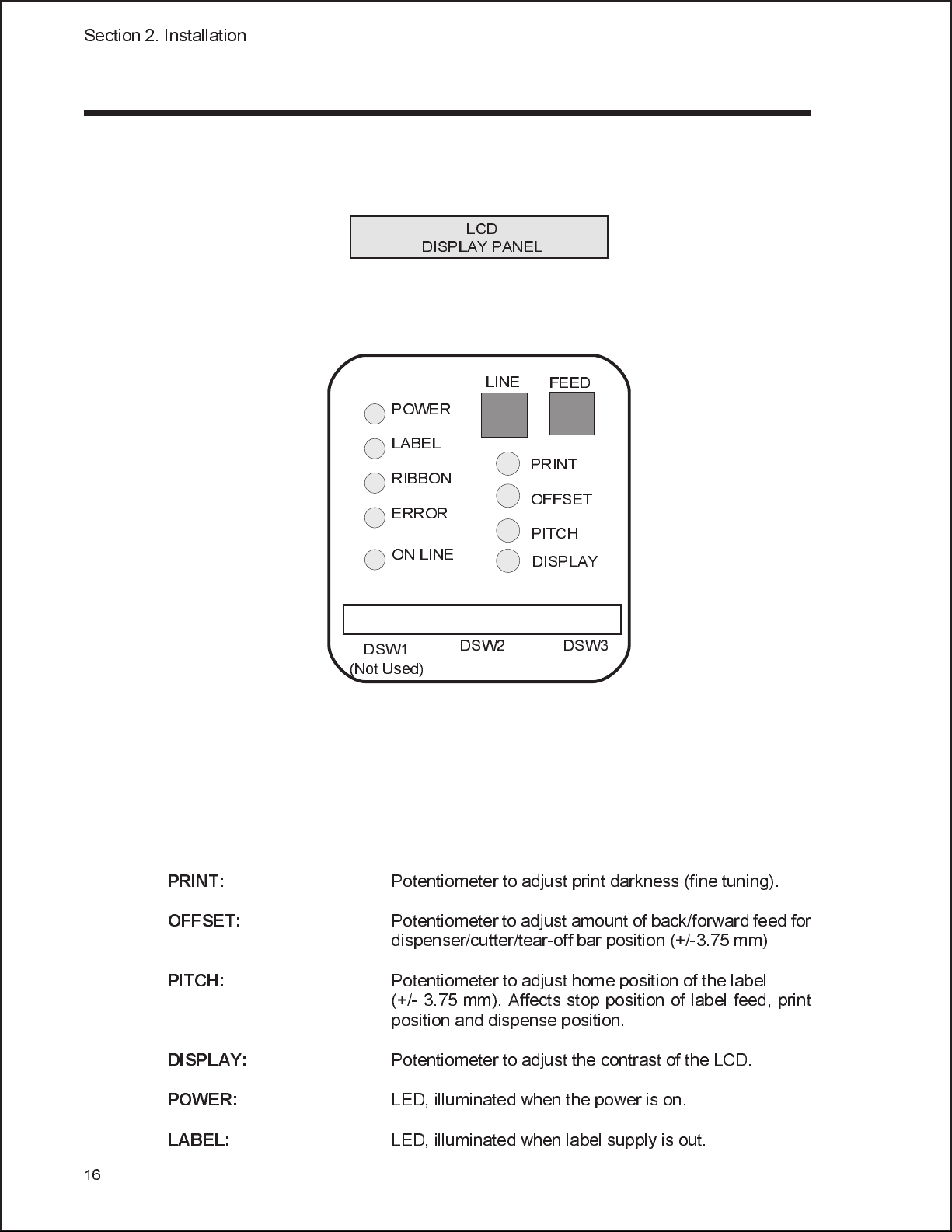
The PTR3E Operator Panel consists of five LED indicators, two momentary
contact switches, two DIP switches, four adjustment potentiometers and one LCD
Display. All of these are accessible from the front of the printer. They are used to set
the printer operating parameters and to indicate the status of the printer to the
operator. After you power on the printer, familiarize yourself with the keys and
indicators as it will help you understand the configuration process.
16
PRINT:
OFFSET:
PITCH:
DISPLAY:
POWER:
LABEL:
Potentiometer to adjust print darkness (fine tuning).
Potentiometer to adjust amount of back/forward feed for
dispenser/cutter/tear-off bar position (+/-3.75 mm)
Potentiometer to adjust home position of the label
(+/- 3.75 mm). Affects stop position of label feed, print
position and dispense position.
Potentiometer to adjust the contrast of the LCD.
LED, illuminated when the power is on.
LED, illuminated when label supply is out.
Page 25
Section 2. Installation
RIBBON:
ERROR:
ON LINE:
LINE:
FEED:
DSW:
LED, illuminated when ribbon motion sensor does not
detect any ribbon motion (ribbon out).
LED, illuminated when there is a system fault such as
an open print head.
LED, illuminated when printer is ready to receive data.
It is turned on and off by toggling the LINE key.
Momentary switch. Pressing this key toggles the printer
between the on-line and off-line mode. When the printer
is on-line, it is ready to receive data from the host. This
key acts as a pause during a print job by taking the printer
off-line. It can also be used as a
Pause
function key to
stop the printer during the printing process.
Momentary switch. Pressing this key feeds one blank
label through the printer when it is off-line. When the
printer is on-line, another copy of the last label will be
printed.
DIP switch array to set operational parameters of the
printer.
LCD:
2 Line x 16 Character LCD display. Used for setting
operationalparameters of the printerand displayingerror
conditions.
17
Page 26

Section 2. Installation
REAR PANEL
AC Input:
AC Fuse:
Interface Slot:
Memory Card Slot:
EXT:
DC 5V:
Input 115V 50/60 Hz connector. Use the cable
provided.
Input power protection. Type 3A/250V.
Connector for Plug-In Interface Module
Connectors for optional PCMCIA Memory Cards.
(Inside Side Cover)
External signal connector, AMP 57-60140.
Power for accessory items.
Fan Fold
Access Panel
Memory Card
Option
AC Power In
Parallel Port
Connector
EXT Port
Connector
Fuse
18
Page 27
SWITCHES AND SENSORS
Section 2. Installation
Ribbon End Sensor:
Head Open Switch:
Label Sensor Unit:
This sensor is a motion detector that signals the printer
when the ribbon supply is turning.
When the print head is opened, this switch is activated
and the printer will stop printing.
This sensor unit contains two types of sensors, one for
label gap and one for Eye-Mark sensing. The sensors
are adjustable over a limited range.
19
Page 28

Section 2. Installation
LABEL SENSOR ADJUSTMENT
The Label Sensor Assembly can be positioned to match the location of the label
registration hole/gap/edge. The diagram below illustrates the relative position of
each sensor along the Label Sensor Unit and its range of movement. To position the
sensors, use the adjustment knob located outside and below the print head
assembly.
Reflective Sensor
Label Gap Sensor
Eye-Mark
on bottom
of liner
14mm
min
Reflective
7mm to 54 mm
Label Gap
The range of sensor adjustment can be
increased to allow the Gap sensor to be
positioned as close as 3mm from the inside label
edge. Contact Panduit for information on how to
make this modification.
20
Label Sensor
Adjustment Knob
Page 29

SECTION 3.
CONFIGURATION
PRINTER DIP SWITCH CONFIGURATION
DIP Switch Panels
There are two DIP switches (DSW2 and DSW3) located underneath a snap-on cover
on the front panel. These switches can be used to set:
Thermal transfer or direct thermal mode
•
Label sensor enable/disable
•
Head check mode
•
Hex dump mode
•
• Single job or multi-job buffer
• Operation mode
In addition, a third DIP switch is located on the RS232C Serial Adapter card and is
used to set the RS232C transmit/receive parameters. (NOTE: Notfactory standard)
Each switch is an eight section “toggle” switch. The ON position is always to the top.
To set the switches, first power the unit OFF, then position the DIP switches.
Finally, after placing the switches in the desired positions, power the printer back
on. The switch settings are read by the printer electronics during the power up
sequence. They will not become effective until the power is cycled.
Printer Set Up
Print Mode Selection (DSW2-1). Selects between direct thermal printing on
thermally sensitive paper and thermal transfer printing using a ribbon.
DSW2-1 SETTING
OFF Therm Xfr
ON Direct Therm
Sensor Type Selection (DSW2-2). Selects between the use of a label gap or a
reflective Eye-Mark detector. See page 20 for the location of these sensors.
ON
OFF
12345678
DSW2
DSW2-2 SETTING
OFF Gap
ON Eye-Mark
DSW2
ON
OFF
12345678
21
Page 30

Section 3. Configuration
Head Check Selection (DSW2-3). When selected, the printer will check for head
elements that are electrically malfunctioning.
DSW2
DSW2-3 SETTING
OFF Disabled
ON Enabled
ON
OFF
12345678
Hex Dump Selection (DSW2-4). Selects Hex Dump mode (see page 37).
DSW2-4 SETTING
OFF Disabled
ON Enabled
ON
OFF
12345678
DSW2
Receive Buffer Selection (DSW2-5). Selects the operating mode of the receive
buffer. See Section 5: Interface Specifications for more information.
DSW2-5 SETTING
OFF Single Job
ON Multi Job
ON
OFF
DSW2
22
12345678
Firmware Download (DSW2-6). Places the printer in the Firmware Download
mode for downloading new firmware into flash ROM.
DSW2-6 SETTING
OFF Disabled
ON Enabled
ON
OFF
12345678
DSW2
Protocol Code Selection (DSW2-7). Selects the command codes used for protocol
control.
DSW2-7 SETTING
OFF Standard
ON Non-Std
ON
OFF
18
DSW2
23 567
4
Page 31

Section 3. Configuration
Print Speed Adjustment (DSW2-8). See page 27.
Mode Selection (DSW3-1 and DSW3-2). Selects the operating mode of the printer.
Batch/Continuous disables the label taken (dispense option) sensor.
DSW3-1 DSW3-2 SETTING
OFF OFF Continuous
OFF ON Tear Off
ON OFF Cutter
ON ON Dispenser
ON
OFF
12345678
DSW3
Label Sensor Selection (DSW3-3). Enables or disables the Label Pitch Sensor. If
the Sensor is enabled, it will detect the edge of the label and position it
automatically. If it is disabled, the positioning must be under software control using
Line Feed commands for continuous media printing.
DSW3
DSW3-3 SETTING
OFF Sensor Used
ON Not Used
ON
OFF
12345678
Back-Feed Selection (DSW3-4). When Back-Feed is enabled, the printer will
position the label for dispensing/cutting and retract it before printing the next
label. See page 38 for information on setting the amount of offset.
DSW3
DSW3-4 SETTING
OFF Enabled
ON Disabled
ON
OFF
12345678
EXT Print Start Signal Selection (DSW3-5). Allows an external device to initiate
a label print.
DSW3-5 SETTING
OFF Disabled
ON
OFF
ON Enabled
12345678
DSW3
Note: This switch must be in the ON position if an external device is used to control
the printer via the EXT connector.
23
Page 32
Section 3. Configuration
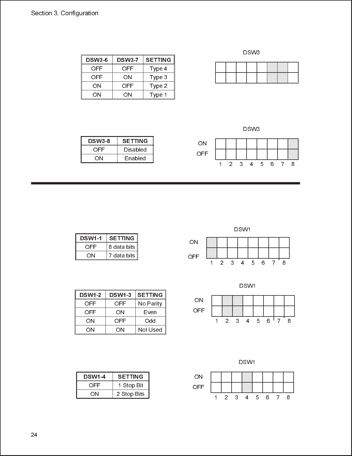
External Signal Type Selection (DSW3-6, DSW3-7). Selects the type of output
signal.
DSW3-6 DSW3-7 SETTING
OFF OFF Type 4
OFF ON Type 3
ON OFF Type 2
ON ON Type 1
Repeat Print via External Signal (DSW3-8). Allows an external device to control
the reprint of the label in the print buffer.
DSW3
DSW3
DSW3-8 SETTING
OFF Disabled
ON Enabled
ON
OFF
12345678
RS232 Transmit/Receive Setting (located on RS232C I/F Module)
The PTR3E comes standard with a parallel port only. Contact Product
Management if serial port is required.
Data Bit Selection (DSW1-1). This switch sets the printer to receive either 7 or
8 bit data bits for each byte transmitted.
DSW1-1 SETTING
OFF 8 data bits
ON 7 data bits
ON
OFF
1
Parity Selection (DSW1-2, DSW1-3). These switches select the type of parity used
for error detection.
DSW1-2 DSW1-3 SETTING
OFF OFF No Parity
OFF ON Even
ON OFF Odd
ON ON Not Used
ON
OFF
12345678
DSW1
2345678
DSW1
24
Stop Bit Selection (DSW1-4). Selects the number of stop bits to end each byte
transmission.
DSW1
DSW1-4 SETTING
OFF 1 Stop Bit
ON 2 Stop Bits
ON
OFF
12345678
Page 33
Section 3. Configuration
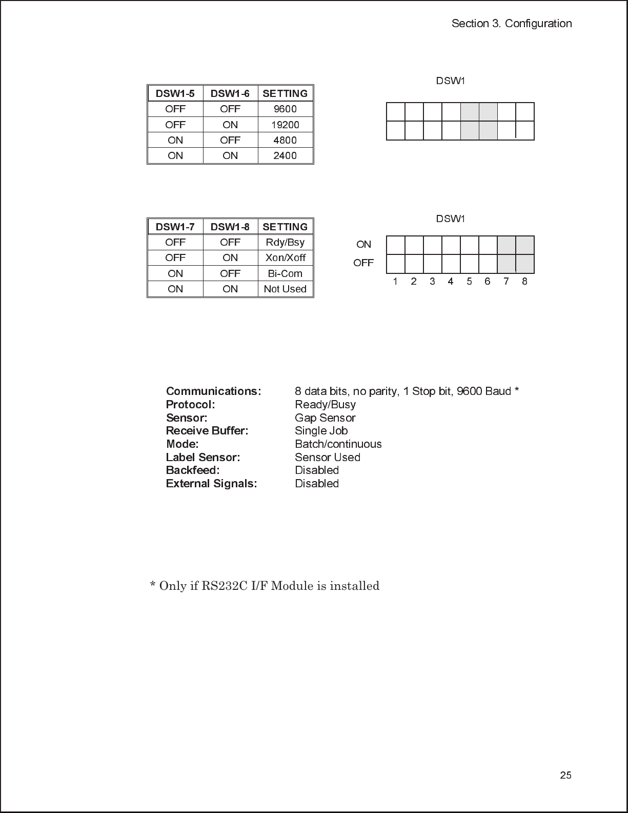
Baud Rate Selection (DSW1-5, DSW1-6). Selects the data rate (bps) for the
RS232 port.
DSW1-5 DSW1-6 SETTING
OFF OFF 9600
OFF ON 19200
ON OFF 4800
ON ON 2400
DSW1
Protocol Selection (DSW1-7, DSW1-8). Selects the flow control and status
reporting protocols. See Section 4: Interface Specifications for more information.
DSW1-7 DSW1-8 SETTING
OFF OFF Rdy/Bsy
OFF ON Xon/Xoff
ON OFF Bi-Com
ON ON Not Used
ON
OFF
12345678
DSW1
Default Settings
Switch Selections - All switches are placed in the OFF position (default) for
shipping. This will result in the following operating configuration:
Communications:
Protocol:
Sensor:
Receive Buffer:
Mode:
Label Sensor:
Backfeed:
External Signals:
8 data bits, no parity, 1 Stop bit, 9600 Baud *
Ready/Busy
Gap Sensor
Single Job
Batch/continuous
Sensor Used
Disabled
Disabled
* Only if RS232C I/F Module is installed
25
Page 34
PRINTER ADJUSTMENTS
The LCD Panel on the PTR3E is used in conjunction with the LINE and FEED
switches by the operator to manually enter printer configuration settings. Many of
the settings can also be controlled via software commands and in the case of conflict
between software and control panel settings, the printer will always use the last
valid setting. If you load a label job that includes software settings and then enter a
new setting via the LCD Panel, the manually set values will be used by the printer.
If you set the values manually and then download a job with software settings, the
software settings will be used.
MODE KEY SEQUENCE INITIAL DISPLAY PAGE
Section 3. Configuration
Normal POWER ONLINE
QTY: 000000
Advanced LINE + POWER ADVANCED MODE 29
Test Print FEED + POWER TEST PRINT MODE
CONFIGURATION
Default Setting LINE + FEED + POWER DEFAULT SETTING
YES NO
Clear Non-Standard Protocol DSW2-7 ON + LINE + FEED +
POWER
Protocol Code Download DSW2-7 ON + POWER + LINE USER DOWNLOAD
Hex Dump DSW2-4 ON + POWER ONLINE
ALT. PROTOCOL
COMPLETE
PRESS THE LINE KEY
QTY: 000000
27
33
34
34
34
35
26
Page 35
Section 3. Configuration
Normal Mode
The printer initially powers on in the ONLINE mode. The user can access the User
Settings using the following procedures:
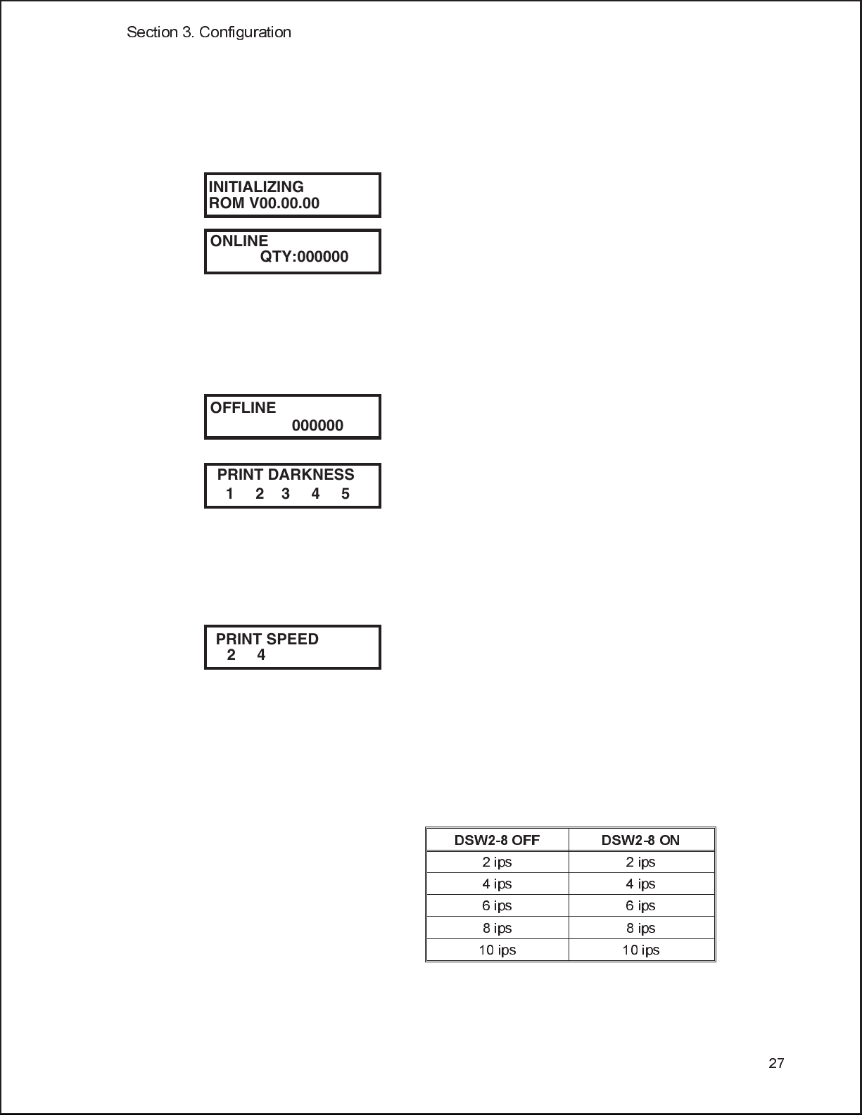
INITIALIZING
ROM V00.00.00
ONLINE
QTY:000000
OFFLINE
000000
PRINT DARKNESS
12345
Display lists the current ROM version of the printer
during the initialization process.
The LCD will display the ONLINE status on the top
line and the bottom line will contain the label quantity
(QTY) status. The message will be changed to OFFLINE
whenever the printer is switched offlineby pressing the
LINE key. As soon as a print job is received, the quantity
line will indicated the number of labels to be printed. As
the label job begins to print, the display will indicate the
number of labels in the print job that remains to be
printed.
Press the LINE key once. When the display changes to
OFFLINE, press the FEED and LINE keys
simultaneously for more than one second.
The LCD now displays the Print Darkness selections.
The current setting is indicated by an underline cursor
under one of the range settings.
1. Press the LINE key to step the cursor to the desired
setting.
2. Once the correct setting is underlined, press the
FEED key to accept the selection and stepthe
display to the next adjustment.
PRINT SPEED
246810
The print speed selections are dependent upon the
printer setting of DSW2-8. The current setting is
indicated by the underlined cursor.
1. Press the LINE key to step the cursor to the
desired setting.
2. Once the correct setting is underlined, press the
FEED key to accept the selection and step the
display to the next adjustment.
DSW2-8 OFF DSW2-8 ON
2 ips 2 ips
4 ips 4 ips
6 ips 6 ips
8 ips 8 ips
10 ips 10 ips
27
Page 36
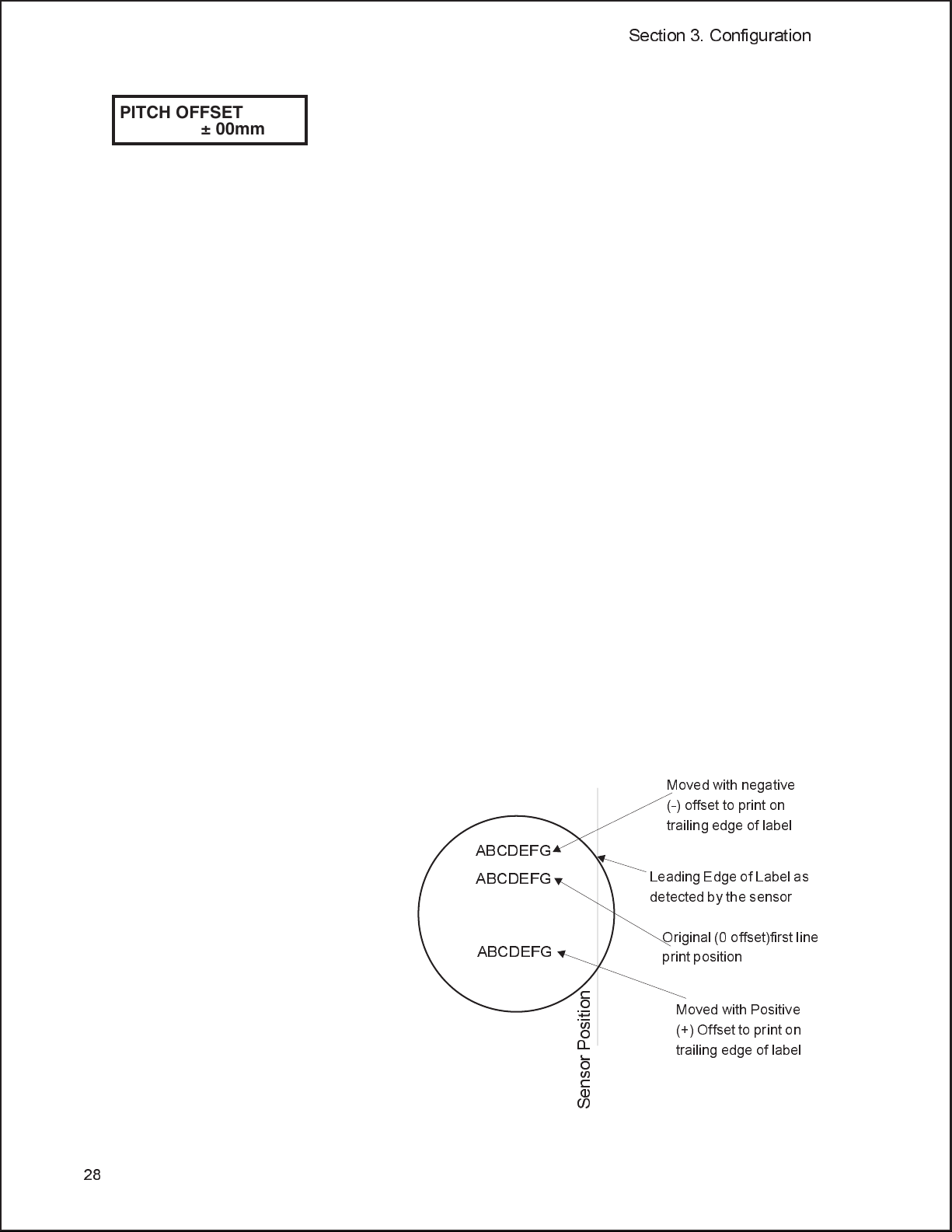
PITCH OFFSET
± 00mm
Section 3. Configuration
The label Pitch distance from the leading edge (the
edge that comes out ofthe printer first) of a label and
the leading edge of the next label. The leading edge
position of the label can be adjusted relative to the
print head +/- 49 mm in increments of 1mm. Once the
position is set, it can be fine adjusted +/- 3.75mm using
the PITCH potentiometer on the Adjustment Panel.
1. The underline cursor will initially be positioned
underneath the Pitch Direction setting. Pressing
the LINE key will step the setting to the positive (+)
or negative (-) selection. A positive selection moves
the leading edge of the label forward (away from the
print head) while a negative selection moves the
leading edge of the label back the mechanism.
2. Once the correct direction is selected, pressing the
FEED key will accept the setting and advance the
cursor to the Offset selection.
3. Use the LINE key to step the first digit of the
counter to the desired setting. The display will
increment one step each time the LINE key is
pressed. The reading will advance to a setting of
4 after which it will automatically wrap and start
at 0 again.
4. Press the FEED key to accept the setting and
advance the cursor to the second digit. Again use
the LINE key to step the desired setting. Once it
is correct, pressing the FEED key will step to the
next adjustment. You may wish to print a test
label after completing the adjustments to ensure
they are correct.
Moved with negative
(-) offset to print on
trailing edge of label
ABCDEFG
ABCDEFG
ABCDEFG
Leading Edge of Label as
detected by the sensor
Original (0 offset)first line
print position
Moved with Positive
(+) Offset to print on
trailing edge of label
28
Sensor Position
Page 37
Section 3. Configuration
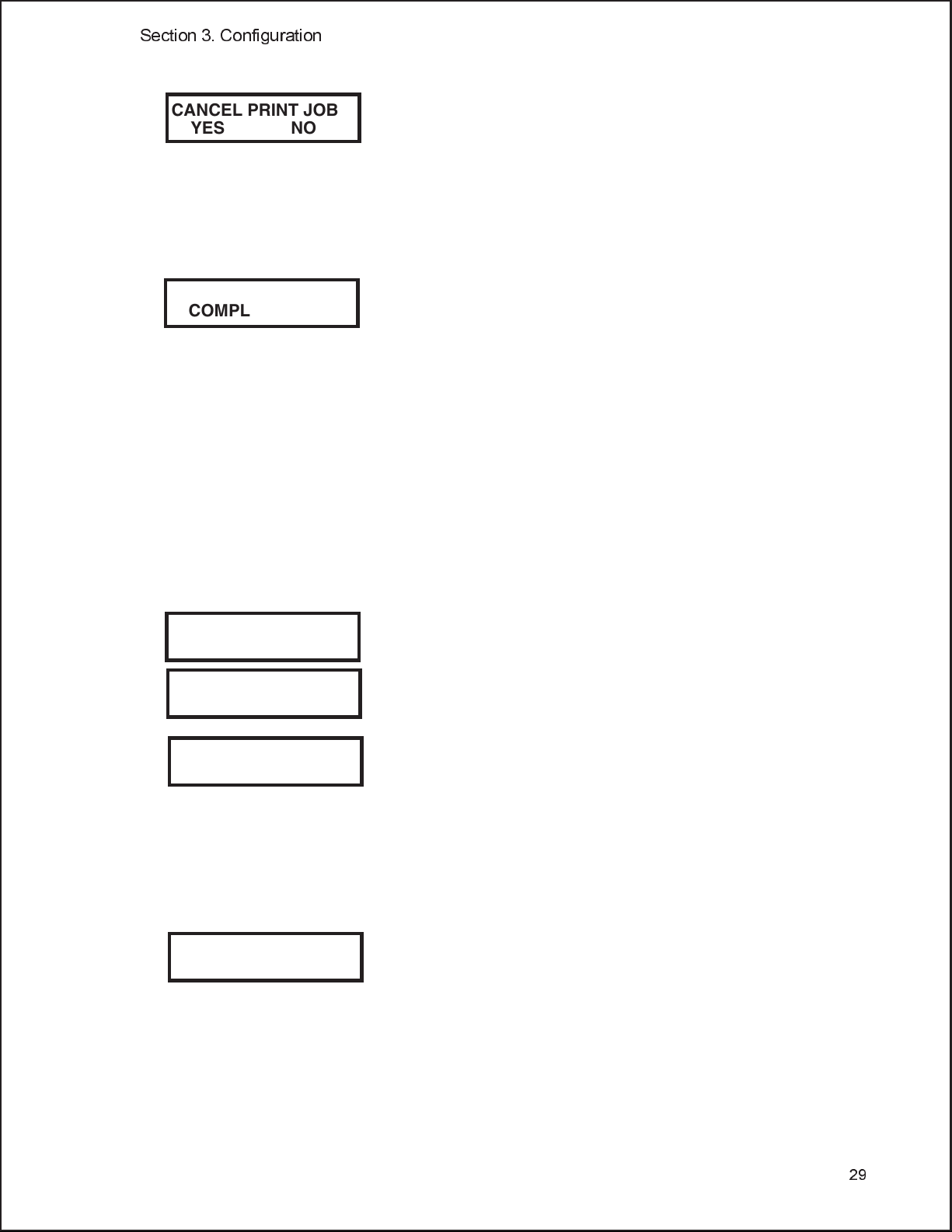
CANCEL PRINT JOB
YES NO
CANCEL PRINT JOB
COMPLETED
ADVANCED MODE
An Advanced Mode is provided to make adjustments that require only occasional
changes. Since they affect the basic operation of the printer, the procedure for
entering this mode is designed to prevent someone from accidentally changing
the settings.
If the printer has print job(s) in memory, selecting
YES will cause the job(s) to be cleared. The default
selection is number Be sure you want to cancel the
print job(s) before selecting yes as the job(s) cannot
be recovered and will have to be retransmitted to
the printer.
1. Use the LINE key to step the underline
cursor to either the YES or NO selection.
2. Once the correct setting is underlined,
pressing the FEED key will accept the
setting.
3. After the print job(s) have been cleared from
memory, the printer will display a
COMPLETED message for 3 seconds and
then return to the initial ONLINE Normal
Mode.
4. If you wish to change any of the settings, you
must enter the User Settings mode again by
taking the printer OFFLINE and pressing
the LINE and FEED keys.
INITIALIZING
ROM V00.00.00.00
ADVANCED MODE
ZERO SLASH
YES NO
AUTO ONLINE
YES NO
The Advanced Mode is entered by pressing the LINE
key while simultaneously turning power on. The
printer will emit one long beep after which the LINE
key is released. Pressing the FEED key will step the
display to the first selection.
This setting determines if a zero is printed with a
slash or without a slash. This setting can also be
controlled via software commands. When YES is
selected, the printer internal fonts will have a slash
through the center of the zero character.
1. Use the LINE keyto step the underline cursor to
either the YES or NO selection.
2. Once thecorrect settingis underlined, pressing
the FEED key will accept thesetting and
advance the display to the Auto Online display.
This setting determines the mode inwhich the printer
powers up. If the YES selection is made, the printer
powers up in the ON LINE mode andis ready to print.
If NO is selected, the printerpowers upin theOFF LINE
mode and must be manually placedin the ON LINE
mode by pressing the LINE key before it is ready to print.
1. Use the LINE key to step the underline to either
the YES or NO selection.
29
Page 38

Section 3. Configuration
2. Once the correct setting is underlined, pressing
the FEED key will accept the setting and
advance the display to the Print Offset display.
PRINT OFFSET
V:+0000 H:+000
Vertical Offset is the distance down from theleading edge
(the edge of the label that comes outof the printer first) to
the first vertical print position. A positive setting moves
the first print position down the length ofthe label.
Horizontal Offset is distance that the label image is
shifted to the right or left on thelabel. The image is
shifted to the left (towards the inside edgeof the label for a
right-hand printer) for a positive settingand itis shifted
to the right (towards the outside edge ofthe label) for a
negative setting. The setting changes the base reference
point for all subsequent label jobs. It’s effect is identical to
the <ESC>A3 BaseReference point command. Since the
printer moves the label in discretesteps equalto the size
of the print dot, the units of measurefor Vertical and
Horizontal Offset distance is dots. The maximum values
that can be set for each is +/-800.
1. Use the LINE key to step the first digit of the
counter to the desired setting. The display will
increment one step each time theLINE keyis
pressed.
2. Press the FEED key to accept the setting and
advance the cursor to the second digit. Again use
the LINE key to step to the desiredsetting.
Once it is correct, pressing the FEED keywill
step to the next adjustment.
3. Once the setting is correct, pressing the FEED
key will accept the setting and advance tothe
next display.
You may wish to print a test labelafter completing the
adjustments to ensure they are correct.
Note: This settingcan be overridden by the Base
Reference Point Command
30
IGNORE CR/LF
YES NO
This selection tells the printer to strip out all carriage
return/line feed repairs (CRLF) from the data stream,
including graphics and 2D bar codes.
1. Use the LINE key to step the underline cursor to
either the YES or NO selection.
2. Once the correct setting is underlined, pressing
the FEED key will accept the setting and
advance the display to the Character Pitch
display.
Page 39
Section 3. Configuration
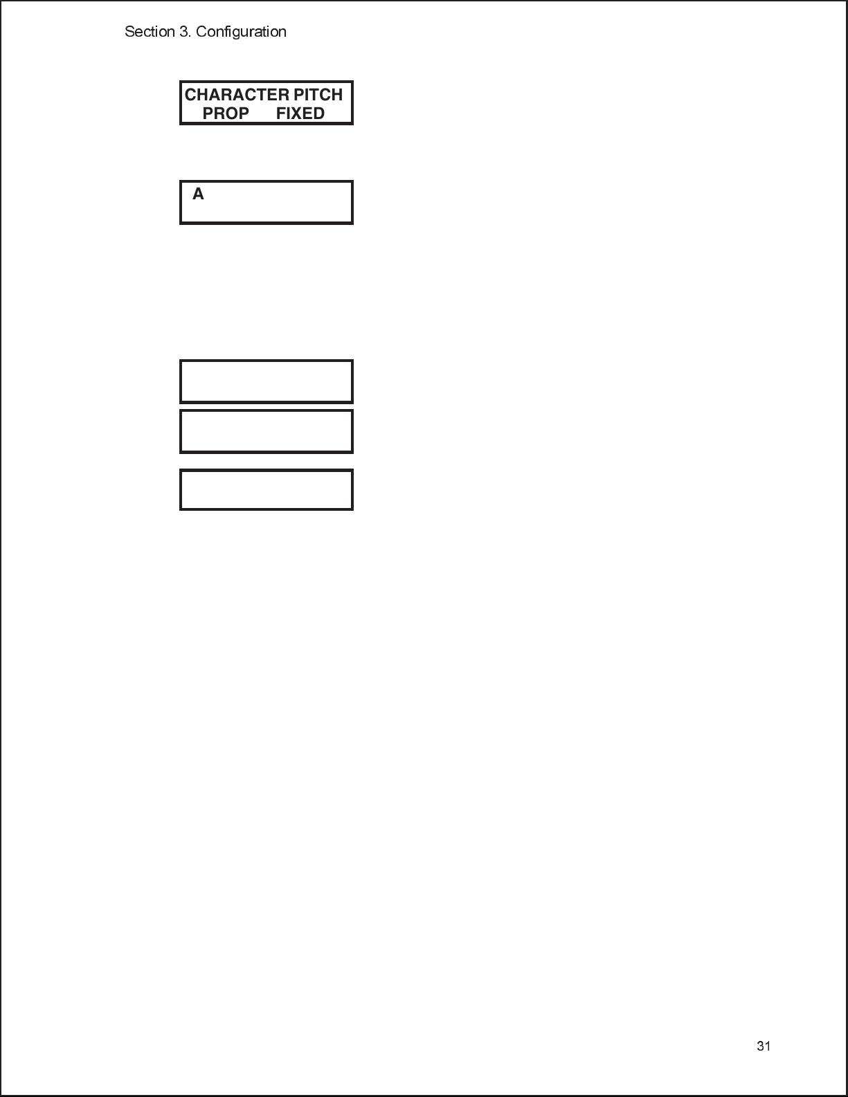
CHARACTER PITCH
PROP FIXED
ADVANCED MODE
This selection allows you to setthe defaultcharacter
pitch to either fixed character spacing or proportional
character spacing.
1. Use the LINE key to step the underline cursor to
the desired setting.
2. Once the correct setting is underlined, pressing
the FEED key will accept the setting and
advance the display. Note: This command can be
overridden by the <ESC>PR or <ESC>PS
Character Pitch Commands. To exit the
Advanced mode, power the printer off and then
back on.
SERVICE MODE
The Service Mode allows the operator to set up the basic operation parameters of the
printer.
ADVANCED MODE
SERVICE MODE
GAP [X.XV]
INPUT [X.XV]
The service Mode is entered from the Advanced Mode
display by pressing the LINE key twice.
The Service Mode display indicates that the printer is in
the Card Mode. To advance to the first selection, press
the FEED key.
The PTR3E printer determines the locationof theleading
edge of thelabel by measuring the differencebetween light
levels when it sees either a label edgeor a black “EYE”
mark. The adjustmentallows you to manually set the
threshold voltage level, between the maximumand
minimum light levels. DIP switchDSW2-2 selects the
sensor type. If DSW2-2 is in the OFF position,the setting
will be for a See-Thru (or Gap) sensorand the LCD will
display “GAP” on the top line along withthe current
setting. If DSW2-2is in the ON position, the LCD will
display “EYE” on the top line with its currentsetting. If
the value entered for the bottom line settingis “0.0V”,
then the printer will automatically calculate the setting
when the first label is fed after the printer ispowered on or
the head is closed. There are some instances wherethe
automatically calculated value must be adjusted to ensure
reliable label feeding, such as whenthe backingopacity or
the reflectance of the EYE mark varies significantly
within a roll of labels or between label rolls. In these
instances the value should be setusing thefollowing
procedures.
31
Page 40
Section 3. Configuration
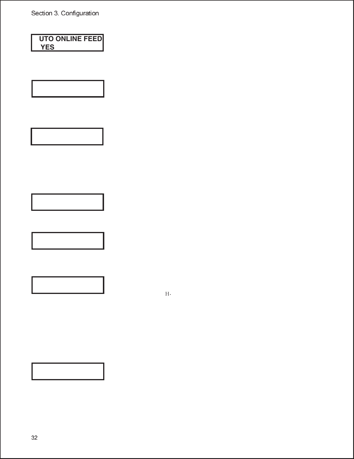
AUTO ONLINE FEED
YES NO
FEED ON ERROR
YES NO
REPRINT W/FEED
YES NO
FORWARD/BACKFEED
DISTANCE DEFAULT
FORWARD/BACKFEED
DISTANCE XXXmm
EURO CODE
D5
SELECT LANGUAGE
ENGLISH
This selection specifies whether or not the printer will automatically
feed a blank label when it is placed in the Online mode.
1. Use the LINE key to step the cursor to desired setting. If
Yes is selected, the printer will feed a blank label anytime
it enters the Online mode. If No is selected, the display
will advance to the mode display.
This selection specifieswhether or not the printer will feed a
blank label automatically when an error condition is cleared...
1. Use the LINE key to step the cursor to desired setting. If
Yes is selected, the printer will feed a blank label anytime
an error condition is cleared. If No is selected, the display
will advance to the mode display.
This selection specifieswhether or not the printer will print the
last printed label stored in memory when the FEED key is
pressed in the Normal Online mode.
1. Use the LINE key to step the cursor to desired setting. If Yes
is selected, the printer will reprint the last label when the
FEED key is pressed when the printer is Online. If the
printer is Offline, pressing the FEED key will feed a blank
label. If No is selected, the display will advance to the mode
display.
This display will only appear when the Backfeed is enabled
(DSW3-4 = OFF).The maximum backfeed distance is 255mm.
1. Use the LINE key to select either the Default or the
Distance selection. If Default is selected, the display steps
to the Web acceleration selection.
2. If Manual setting is selected, use the LINE key to advance
the distance to the desired setting. Each time the LINE key
is pressed, the Distance will advance 1 mm. The maximum
distance is 255mm.
3. Once the desired distance is set, press the FEED key
to accept the setting and step to the next display.
This selection allows the user to specify the hexidecimal code
for the character which is replaced with the Euro Character.
The default is D5
1. The underline cursor should be positioned underneath
the first digit selection. Use the LINE key to step to the
desired setting.
2. Press the FEED key to advance the underline cursor to
the second digit of the desired hexidecimal code.
3. Press the LINE key to step to the desired setting.
4. When the setting is correct, press the FEED key to
accept the setting and step to the next display.
This selection allows the user to select the character set used by the
printer. The selections are English, French, German, Spanish
Italian and Portuguese. The default is English.
1. Press the LINE key to advance to the desired language
setting.
2. When the setting is correct, press the FEED key to accept
the setting and step to the next display.
.
H
32
Page 41
Section 3. Configuration
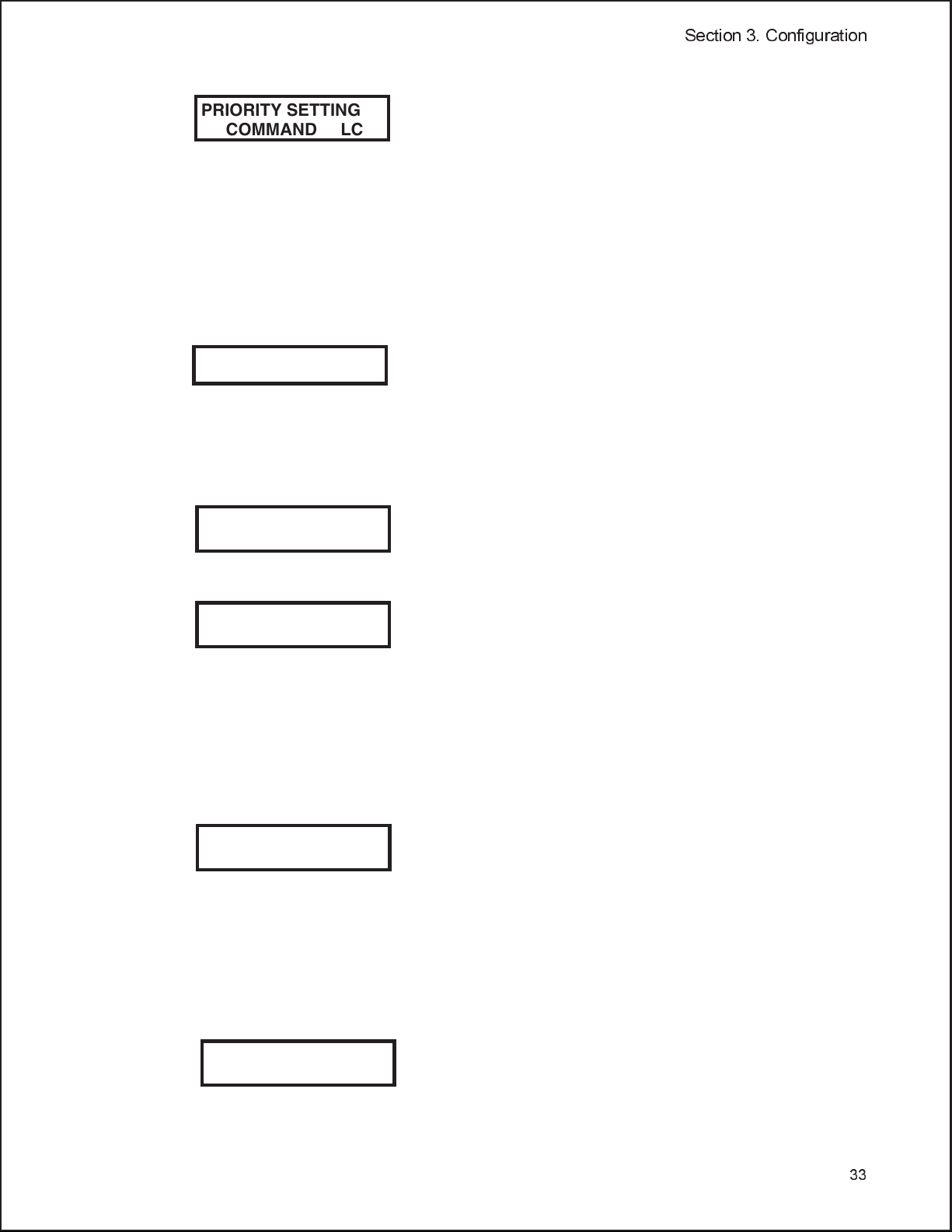
PRIORITY SETTING
COMMAND LCD
SERVICE MODE
This selection allows the user to assign a priority for Print
Darkness, Print Speed and Print Offset.
1. Use the LINE key to step to the desired priority. If
LCD is selected, the setting established via the LCD
display/menu system will be used for an incoming
label job, regardless of any different command
settings. If Command is selected, any commands in
the label job will take precedence and be used for
printing the job and the LCD Display will reflect the
new setting.
2. Once the desired setting is selected, press the FEED
key to accept the setting and step to the next display.
The Service mode is exited by powering the printer off
and then back on.
TEST PRINT MODE
The Test Print Mode offers five different printer status labels for troubleshooting.
If DSW3-5 is On, the Test Print cycle must be initiated with a Print Start command.
This option allows you to print a test label. It is
recommended that you print a testlabel afterhave
INITIALIZING
ROM V00.00.00.00
TEST PRINT MODE
CONFIGURATION
TEST PRINT SIZE
10 CM
Note: This display
does not appear when
a Memory Test Print is
chosen. Only a small
Memory Test Print
label can be printed.
PRESS FEED KEY
TO STOP PRINTING
changed any of the settings in the Advanced Mode.
The test label allows you to verify thatyou indeed
did make the desired changes. To enter the User
Test Print Mode, power the printer on while
pressing the FEED key. The printerwill beep.
Release the FEED key and the printer willdisplay
the Test Print Mode message on the LCD panel:
1. Use the LINE key to step the underline cursor to
the type of test labels you wish to print. The
choices are:
Configuration
Bar Code
Head Check
Memory
Factory
Once you have selected the type of test label to be
printed, use the FEED key to accept the selection and
the display advances to the Test Print Size display.
This display allows you to select the label width.
1. Use the LINE key to select the label width. Each
time the LINE key is pressed, the label size
advances 1 cm until it reaches a maximum width
of 10 cm, at which point it will wrap to the
smallest size of 4 cm.
2. Pressing the LINE key accepts the selection
3. Press the FEED key to start printing test labels
continuously.
4. Press the FEED key to stop the printer.
5. To exit the Test Print Mode, power the printer off
and then back on.
33
Page 42

Section 3. Configuration
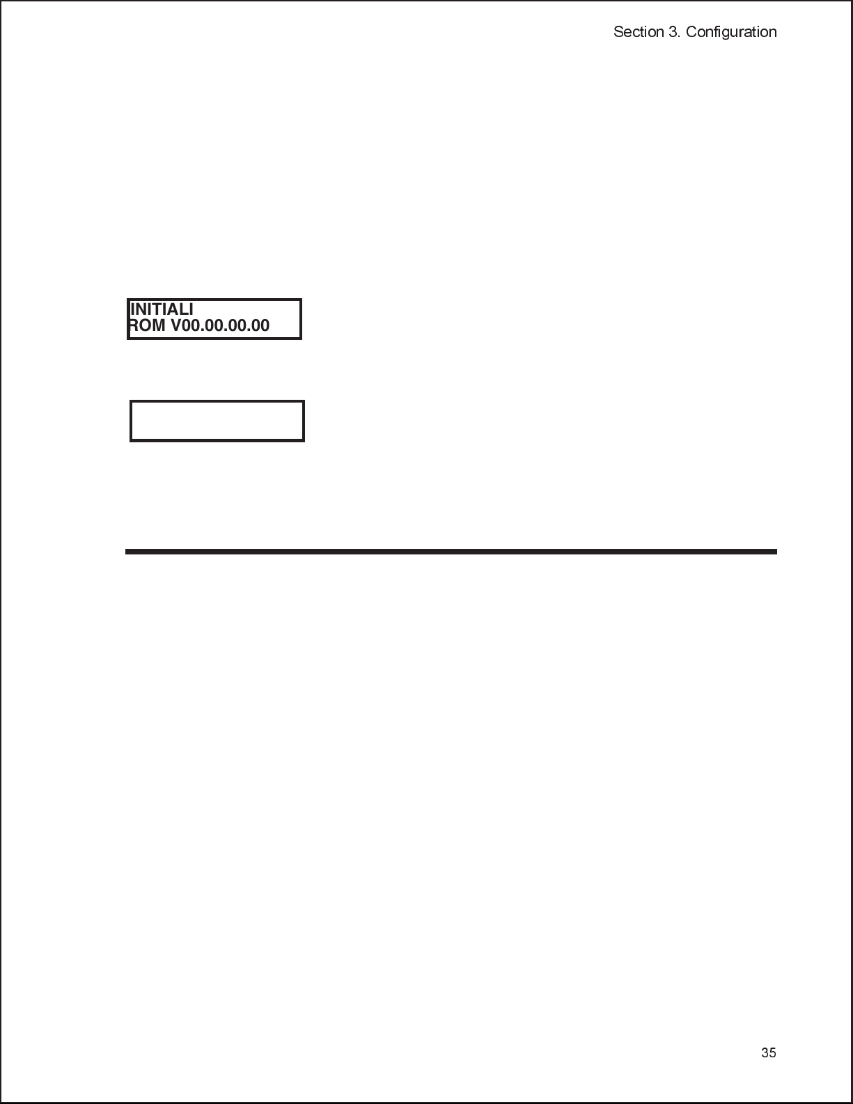
DEFAULT SETTING MODE
Occasionally it is desirable to reset all printer configuration settings to their original default
conditions. This allows the operator to start reconfiguration of the printer starting from a
known set of conditions.
INITIALIZING
ROM V00.00.00.00
DEFAULT SETTING
YES NO
DEFAULT SETTING
COMPLETED
You enter the Default Setting Mode by pressing the LINE and
FEED keys while simultaneously powering the printer on. The
printer will emit one long beep after which the FEED and
LINE keys should be released.
1. Use LINE key to select either the YES or number
2. Once the desired setting is selected, pressing the FEED
key will accept the selection and the printer will reset to
the original default conditions.
3. When the printer has completed the reset process, the
Default Setting Completed display will appear. At this
time the printer is in the default configuration.
4. To exit the Default Setting Mode, power the printer off
and then back on.
CLEAR NON-STANDARD PROTOCOL
The standard protocol codes used by the printer can be modified to accommodate the
requirements of different host systems. However, if the printer is to be used with a system that
does not use the custom protocol codes, they can be cleared and the default protocol codes
H
reactivated. The default values are: STX = 7B
H
,CAN=21H, and OFFLINE = 5DH.
7E
INITIALIZING
ROM V00.00.00.00
ALT. PROTOCOL
DEFAULT COMPLETE
To Clear Non-Standard protocol codes, DSW2-7 is placed in the
OFF position and the printer powered on while simultaneously
pressing the LINE and FEED keys. The printer will emit one
long beep at which time the LINE and FEED keys should be
released.
1. When the keys are released, the printer will replace the
Alternate protocol codes with the default values.
2. After the default setting is complete, the printer will
emit two short beeps indicating the process is complete.
3. To exit the mode, power the printer off and then back
on.
, ETX = 7DH, ESC = 5EH, ENQ = 40H, NULL =
DOWNLOAD USER DEFINED PROTOCOL CODES
The user can define a set of custom protocols codes and download them to the printer using
the <ESC>LD command.
INITIALIZING
ROM V00.00.00.00
USER DOWNLOAD
PRESS THE LINE KEY
USER DOWNLOAD
WAITING
To enter the User Download mode, DSW2-7 is placed in the
OFF position and the printer is powered on while
simultaneously pressing the LINE key. The printer will emit
one long beep after which the LINE key should be released.
1. Press the LINE key. The printer is now waiting for the
datatobesent.
2. Transmit the download data command stream to the
printer.
3. After the data has been received, the printer will beep
and print a status label. If it does not beep and print a
status label, the printer did not accept the data.
34
Page 43
Section 3. Configuration
4. If the printer did not beep and print a status label, turn
the printer off and check your data stream for errors
and start the download process over.
5. If the custom codes are correct, press the FEED key to
accept them and terminate the download process. If
they are incorrect, turn the printer off without pressing
the FEED key and begin the process again.
HEX DUMP MODE
In addition to the User Test PrintLabels, theprinter canprint thecontents ofthe receivebuffer
in a hexadecimal format to allow the data stream to be examined for errors and
troubleshooting.
INITIALIZING
ROM V00.00.00.00
ONLINE
QTY:000000
The Hex Dump Mode is entered by placing DSW2-4 in the ON
position and powering the printer on.
1. The printer is now ready to receive data.
2. Send the data stream to the printer.
3. The received data will be printed in a hexadecimal
format
4. To return the printer to normal operation, place
DSW2-4 in the OFF position and power the printer off
andthenbackon.
POTENTIOMETER ADJUSTMENTS
PITCH
After the pitch has been set with the LCD Control Panel, it is sometimes desirable to
make minor adjustments. This can be done using the PITCH potentiometer on the
front panel. This potentiometer is set at the factory so that it has a range of +/-3.75
mm. The midpoint setting should have no effect on the pitch. Turning the
potentiometer all the way clockwise should move the print position 3.75 mm up
towards the top edge of the label. Turning it all the way counter clockwise should
move the print position down 3.75 mm.
1. While depressing the FEED key on the front panel, power the printer on.
2. When you hear one beep from the printer, release the FEED key and the
printer will display on the LCD panel a message asking what type of Test
Label you want to print.
3. Use the LINE key to step to the Configuration selection and press the FEED
key to accept the selection.
4. Use the LINE key to select the Test Label size. After the size is selected,
press the FEED key to accept the selection and the printer will begin to print
test labels continuously.
5. Adjust the PITCH potentiometer on the front panel until the first print
position is at the desired location on the label. If the potentiometer does not
35
Page 44

Section 3. Configuration
have enough range, then you will have to change the pitch setting using the
LCD front panel display.
6. Press the FEED key to stop the printer.
7. To exit the Test Label mode, power the printer off and then back on.
Adjusting the PITCH potentiometer will affect the stop position of the label.
BACKFEED OFFSET
When a label is printed it must be correctly positioned for dispensing and
application. The Backfeed adjustment is used to position the label so that it is fully
dispensed and ready for application. It may then be necessary to reposition the next
label before printing. The Backfeed (repositioning of the label) operation is enabled
if DSW3-4 is in the Off position. If backfeed is enabled, placing DSW3-1 in the Off
position will cause the backfeed operationto be performed immediately before each
label is printed. If DSW3-1 is in the On position, the backfeed operation is
performed as soon as the dispensed label has been printed and taken from the
printer.
The amount of backfeed is controlled by the OFFSET potentiometer on the DIP
Switch Panel inside the cover. When turned all the way counterclockwise, the
amount of backfeed is +3.75 mm, and -3.75 mm when turned all the way
counterclockwise.
1. Turn the printer on.
2. Press the LINE key to place the printer in the Off Line status.
3. Press the FEED key to feed out a blank label.
4. Adjust the position using the OFFSET potentiometer on the front control
panel and feed another label by depressing the FEED key. Repeat this
procedure until the label is fully released from the liner.
DISPLAY
This potentiometer is used to adjust the contrast of the LCD display for optimum
viewing under various lighting conditions.
PRINT
The PRINT potentiometer is used to adjust the amount of heat (i.e., power) applied
to the head for printing. It provides a continuous range of adjustment. Maximum
print darkness is obtained by turning the potentiometer all the way clockwise and a
maximum counterclockwise setting will give the lightest print.
36
NOTE: The PRINT potentiometer adjustment will affect the darkness in all of the
commend code speed and darkness ranges.
Page 45

DISPLAY COUNTER VALUES
The internal counters are used to track the number of kilometers of media that has been
processed through the printer, the number of labels cut and/or the number of label
dispensed. These values can be used to track component life for service and
maintenance functions. The current counter settings are displayed on the
Factory/Service mode Test Label. To print the Factroy/Service Test Label, the
following procedure must be used:
1. Turn the printer OFF and place DSW2-4 in the ON position.
2. Open the print head by releasing the Head Latch.
3. While simultaneously pressing the LINE and FEED keys, turn the printer
ON.
4. Close and latch the print head.
Section 3. Configuration
5. The LCD panel should read:
MAINTENANCE MODE
DIPSW2-4 ON->OFF
6. Place DSW2-4 in the OFF position.
7. The LCD panel should indicate that the printer is in the FACTORY MODE.
FACTORY MODE
8. Press the FEED key and the display will advance to the COUNTER CLEAR
message screen. Make sure that the NONE selection is displayed on the
bottom line. If it is not, press the LINE key once until ALL is displayed.
COUNTER CLEAR
NONE
9. Press the FEED key to initiate the Test Label print mode. Then press the
LINE key to begin printing Test Labels. The printer will print Test Labels
continuously until the FEED key is pressed again, which pauses the printer.
Test Labels will again start printing as soon as the FEED key is pressed
again.
WARNING: The Test Label is designed to print on a full width label. If smaller
labels are used, the print head may be damaged if more than one label is printed.
10. The counter readings and ROM version are printed on the label along with
other pertinent information.
11. Turn the unit OFF and reset the DIP switches to the proper operating
positions before powering the printer back ON.
37
Page 46

Section 3. Configuration
38
Page 47

CLEANING AND MAINTENANCE
INTRODUCTION
This section provides information on user maintenance for the PTR3E. This
section contains the following information.
Adjusting the Print Quality
•
Cleaning the Print Head, Platen and Rollers
•
Cleaning the Sensors
•
Replacing the Print Head
•
Replacing the Fuse
•
PROCEDURES
ADJUSTING THE PRINT QUALITY
SECTION 4.
The PTR3E printer has two different means of adjusting the quality of the print:
print darkness and speed. When adjusting the printer for optimum print quality, a
bar code verifier system should be used. The human eye is a poor judge of the
relative widths of the bars in a symbol, a characteristic that is extremely important
for good bar code quality.
Darkness (Print)
This adjustment allows the user to control (within a specified range) the amount of
power that is used to activate the individual print head heat elements. It is
important to find a proper print darkness level based on your particular label and
ribbon combination. The printed images should not be too light nor should the ink
from the ribbon “bleed.” The edgesof eachimage should be crisp and well defined.
The Print Darkness range can be set using the front panel LCD panel (see page 26)
or by downloading the setting using the Print Darkness software command. There
are five ranges, with 1 being the lowest and 5 being the highest. Once the range has
been selected, the PRINT Potentiometer on the front panel can be used to make
finer adjustments.
39
Page 48
Section 4: Cleaning and Maintenance
Print Potentiometer
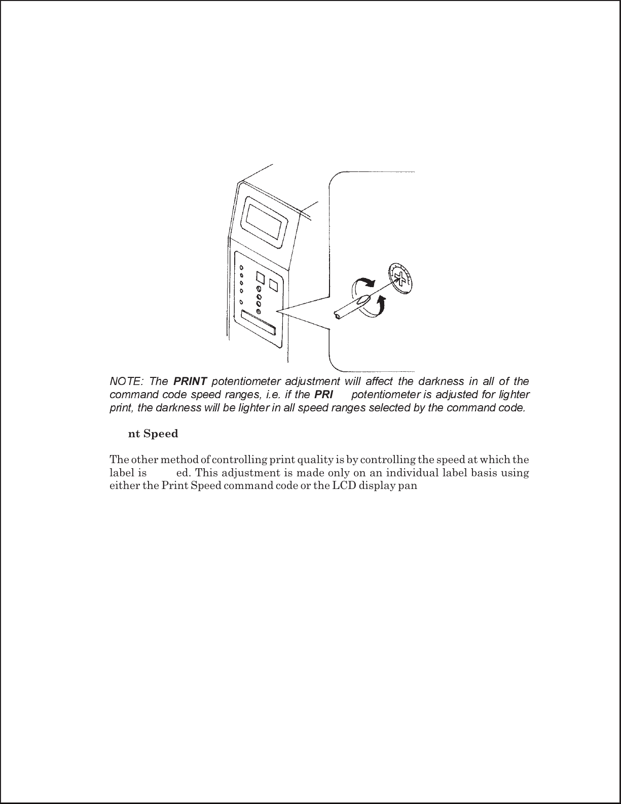
The fine adjustment for Print Darkness is the PRINT potentiometer on the
operator panel. It provides a continuous range of adjustment, allowing you to make
precise changes. Use a small cross-point screwdriver, turning clockwise for darker
print and counterclockwise for lighter print.
NOTE: The
command code speed ranges, i.e. if the
PRINT
potentiometer adjustment will affect the darkness in all of the
PRINT
potentiometer is adjusted for lighter
print, the darkness will be lighter in all speed ranges selected by the command code.
Print Speed
The other method of controlling print quality is by controlling the speed at which the
label is printed. This adjustment is made only on an individual label basis using
either the Print Speed command code or the LCD display panel. Changing the print
speed allows the user tocontrol the amount of time allowed for print element cooling
before the media is stepped to the next print position. It is especially critical when
printing “ladder” bar codes (bar codes printed with the bars parallel to the print
line). When printing a “ladder” bar code, it is important to allow the head to cool
sufficiently before stepping to the next position. If it does not have sufficient time to
cool, the bar will be “smeared” on the trailing edge.
The Print Speed can be set to 2, 4, 6, 8 or 9 inches per second (with DSW2-8 OFF) or
2, 4, 6, 8 or 10 inches per second (DSW2-8 ON) using the LCD panel (see page 26) or
using software. The software command will override the any setting entered using
the LCD panel.
40
Page 49

Section 4: Cleaning and Maintenance
CLEANING THE PRINT HEAD, PLATEN AND ROLLERS
Supplies Needed: PTR-CLN printer cleaning kit
Includes: 4 oz. (116 ml) bottle cleaning solution with MSDS,
cleaning pens, 100 swabs, 12 alcohol wipes and instructions
Cleaning the Print Head and Platen
1. Turn the printer OFF and remove the power cable.
2. Open the Top Access and Side Access doors.
3. Open the Print Head by pushing the Head
Latch toward the rear of the printer. The
Print Head is spring-loaded and will
automatically open as soon as the Head
Latch is disengaged. Remove the ribbon.
4. Apply isopropyl alcohol to a cotton swab.
5. The Print Head faces downward along the
front edge of the assembly. Pass the end of
Print Head
the dampened swab along the entire width
of the Print Head (you may need to move
the ribbon out of the way to do this).
Platen
Head Latch
6. Check for any black coloring or adhesive
on the swab after cleaning.
7. Repeat if necessary until the swab is clean after it is passed over the head.
8. The head should be cleaned at least every time the ribbon is changed and
more often in harsh environments.
9. Apply isopropyl alcohol to one of the cotton swabs.
10. The Platen is the rubber roller directly below the Print Head.Itshouldbe
cleaned of any ribbon or label residue.
41
Page 50
Section 4: Cleaning and Maintenance
Cleaning the Rollers and Guides
1. The Label Load Drive is located
underneath the Label Hold-Down.It
should be cleaned of any label residue or
foreign material. The Label Hold Down
Roller is located on the underneath side of
the Label Hold Down. It should also be
cleaned of any residue or foreign material.
2. There are two Label Edge Guides used in
guiding the labels through the printer.
They should be cleaned of any residue or
foreign material.
3. Repeat when necessary. The rollers and
guides should be cleaned whenever foreign matter such as dust or adhesive is
present.
CLEANING THE SENSORS
There are two sensors that are used to control the positioning of the label. One is a
transmissive see-thru sensor that detects the edge of the label by looking through
the liner which is translucent and detecting the presence of the opaque label. The
other is a reflective sensor that detects the light reflected from the bottom of the
label liner. When a printed black Eye-Mark passes through the beam, the light is no
longer reflected back to the sensor detector, indicating to the printer that it should
use this position as the start of a new label. When dust, dirt or other foreign matter
interferes with the light path of either of these sensors, the results is erratic label
positioning. These sensors should be cleaned regularly, at least every two rolls of
labels. They are both located on an adjustable assembly in the throat of the printer
between the Label Hold Down and the Print Head.
Label Edge
Guides
Label Hold
Down Roller
Label Drive
Roller
Sensor
Assembly
42
1. Turn the printer OFF and remove the power cable.
2. Open the Top Access and Side Access doors.
3. Open the Print Head by pushing the Head Latch toward the rear of the
printer. The Print Head is spring-loaded and will automatically open as soon
as the Head Latch is disengaged. Remove the ribbon.
4. Apply isopropyl alcohol to a cotton swab.
5. Carefully insert the swab between the top and bottom portions of the Sensor
Assembly. The location of the sensors is identified by two marks on the front
of the assembly.
6. Move the swab back and forth to clean any residue from the sensors (see page
20 for location of sensors).
Page 51
REPLACING THE PRINT HEAD
The print head on the PTR3E printer is a user-replaceable item. If it becomes
damaged for any reason, it can be easily removed and replaced. Contact Technical
Support for information on obtaining a new print head.
Section 4: Cleaning and Maintenance
Supplies needed:
No. 2 Phillips screwdriver (a magnetic tip is
helpful), Replacement Print Head (available
through Panduit Printer Repair Department)
1. Turn the printer OFF and remove the power cable.
2. Open the Top and Side Access doors.
3. Open the Print Head by pushing the Head Latch toward the rear of the
printer. The Print Head is spring-loaded and will automatically open as soon
as the Head Latch is disengaged.
4. Remove the ribbon from the Ribbon Rewind Spindle if necessary.
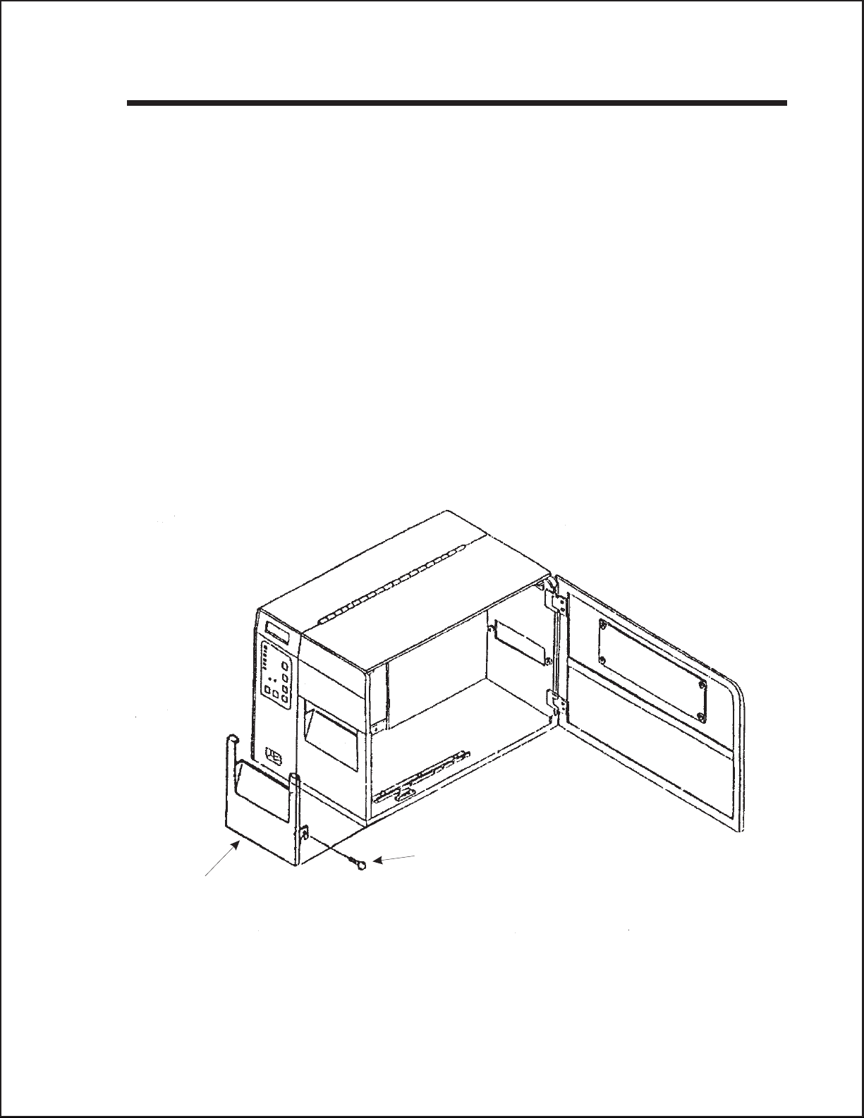
5. Remove the Label Cover Assembly by removing the securing screw from
the assembly.
Label Cover
Label Cover securing
screw
43
Page 52
Section 4: Cleaning and Maintenance
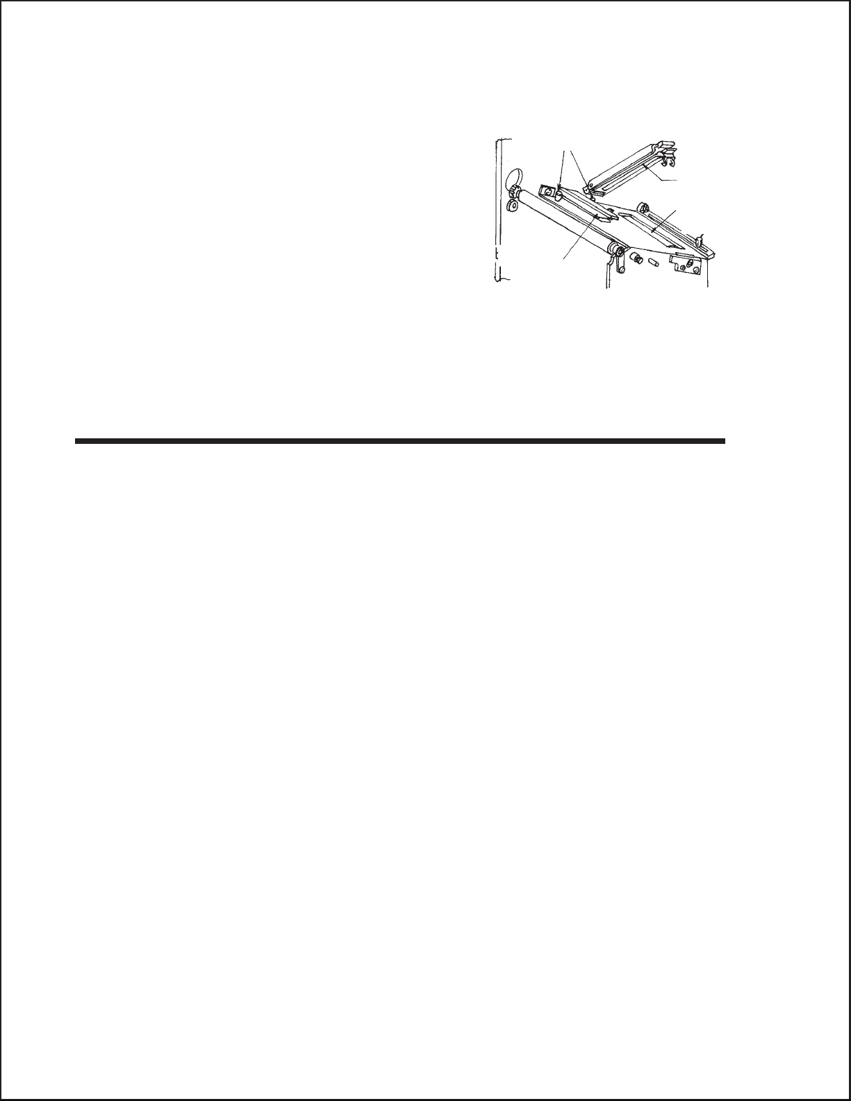
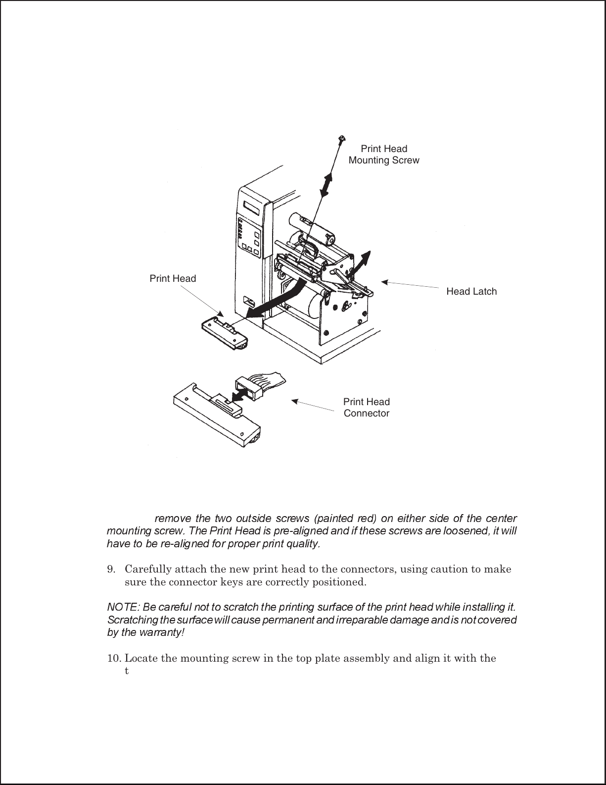
6. View the Print Head from the front of the printer. Locate the center mounting
screw on the top of the assembly. Unscrew this screw and set it aside.
7. The Print Head should now be loosened from the top of the assembly by
grasping either side and carefully pulling it down.
Print Head
Print Head
Mounting Screw
Head Latch
Print Head
Connector
8. Disconnect the signal and power cables from the print head connectors and
set the Print Head aside.
DO NOT
remove the two outside screws (painted red) on either side of the center
mounting screw. The Print Head is pre-aligned and if these screws are loosened, it will
have to be re-aligned for proper print quality.
9. Carefully attach the new print head to the connectors, using caution to make
sure the connector keys are correctly positioned.
NOTE: Be careful not to scratch the printing surface of the print head while installing it.
Scratchingthe surface willcause permanent andirreparable damage and is not covered
by the warranty!
10. Locate the mounting screw in the top plate assembly and align it with the
tapped hole in the new print head.
44
11. Re-secure the print head by tightening the screw.
Page 53

REPLACING THE FUSE
Supplies needed: 250V 3A Fuse
1. Turn the printer power OFF and remove the power cable.
2. On the back of the printer, locate the Fuse Cap on the right-hand side of the
AC connector.
3. Unscrew the cap and remove the defective fuse.
4. Replace with a new 250V 3A fuse.
5. Screw the cap back onto the printer and replace the power cord.
Section 4: Cleaning and Maintenance
45
Page 54

Section 4: Cleaning and Maintenance
46
Page 55

INTERFACE TYPES
The parallel interface for the PTR3E printer is a high speed, bi-directional interface
that conforms to the IEEE1284 specification (ECP mode on some computers). The
interface is also compatible with the older Centronics parallel interface standard. If it
does not detect the correct IEEE1284 signals I the interface connection, it will
automatically operate in the standard Centronics mode which is much slower. To use
the IEEE1284 parallel interface to its fullest capability requires that the host also have
an IEEE1284 compatible interface and that the two be connected with a cable that
meets the IEEE1284 specification. If either of these two are not present, the data rate
is severely compromised.
In order to provide flexibility in communicating with a variety of host computer
systems all “e” printers use a Plug-In Interface Module. The IEEE1284 Interface
module is shipped with the printer unless another interface type is specified at the time
of the order. A serial interface at a high speed to 57.6k bps is also available.
The Parallel interface will probably be the most useful in communicating with IBM
purchase and compatibles. The RS232C Serial interface allows connectivity to a
number of other hosts.
SECTION 5.
INTERFACE SPECIFICATIONS
WARNING: Never connect or disconnect interface cables (or use a switch box) with
power applied to either the host or the printer. This may cause damage to the
interface circuitry in the printer/host and is not covered by warranty.
IEEE1284 PARALLEL INTERFACE
The parallel interface for the PTR3E printer is a Plug-In Interface Module that can be
installed by the user. It conforms to the IEEE1284 specification. It will automatically
detect the IEEE1284 signals and operate in the high speed mode. If it does not detect the
IEEE1284 signals, it will operate in the standard Centronics mode, which is significantly
slower. For this reason, an interface cable and host interface conforming to the IEEE1284
specification must be present to fully utilize the speed capabilities. This interface also
operates bi-directionally and can report the status of the printer back to the host.
ELECTRICAL SPECIFICATIONS
Printer Connector AMP 57-40360 (DDK) or equivalent
Cable Connector AMP 57-30360 (DDK) or equivalent
Cable IEEE1284 Parallel, 10 ft. (3 m) or less
Signal Level High = +2.4V to +5.0V
Low = 0V to -0.4V
47
Page 56
Section 5. Interface Specifications
RS232C SERIAL INTERFACE
The High Speed Serial Interface is a Plug-In Interface Module. The PTR3E comes standard
with parallel interface.
GENERAL SPECIFICATIONS
Asynchronous ASCII
Half-duplex communication
Ready/Busy Hardware Flow Control
Pin 20, DTR Control
Pin 4, RTS Error Condition
X-On/X-Off Software Flow Control
Bi-Directional Communication (ENQ/Response)
Data Transmission Rate
Character Format
2400, 4800, 9600 and 19200 bps
1 Start Bit (fixed)
7 or 8 data bits (selectable)
Odd, Even or No Parity (selectable)
1 or 2 Stop bits (selectable)
ELECTRICAL SPECIFICATIONS
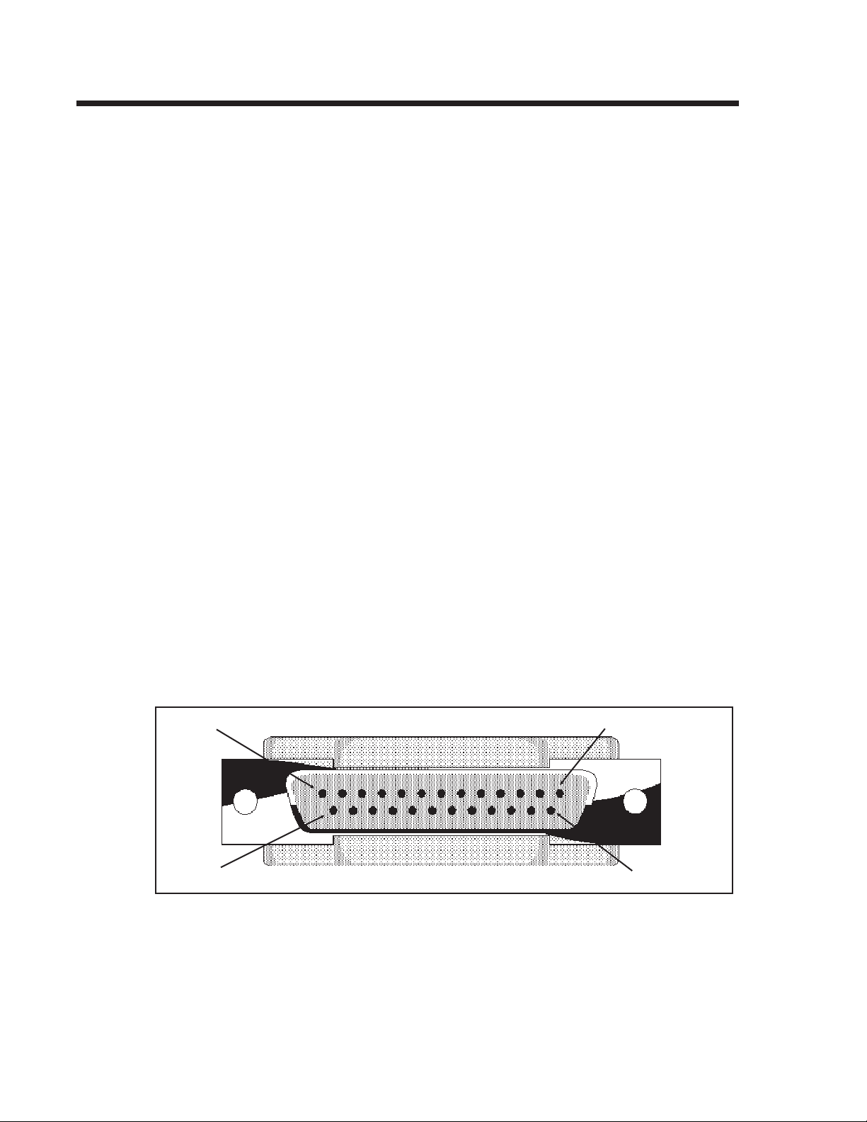
Connector DB-25S (Female)
Cable
DB-25P (Male), 50 ft. maximum length. For cable
configuration, refer to Cable Requirements
appropriate to the RS232C protocol chosen.
48
Pin 13
Pin 25
Signal Levels
Pin 1
Pin 14
High = +5V to +12V
Low = -5V to -12V
Page 57

This section has been compiled to help you produce output on the PTR3E. Use this
section to make sure the basics have been checked before deciding you are unable to
proceed any further. The section is divided into four parts:
Initial Checklist
•
IEEE1284 Parallel Interface
•
RS232C Serial Interface
•
Error Signals
•
INITIAL CHECKLIST
1. Is the printer powered up and On-Line?
2. Is the ERROR light on the front panel off? If this light is on, it may
SECTION 6.
TROUBLESHOOTING
mean the Print Head Assembly or the Label Hold-Down is not closed
and latched in position.
3. Are the LABEL and RIBBON lights on the front panel off? If these
lights are on, the labels or ribbons may be incorrectly loaded.
USING THE IEEE1284 (PARALLEL) INTERFACE
1. Is the IEEE1284 parallel printer cable connected securely to your
parallel port (DB-25S Female) on the PC and to the IEEE1284 connector
on the printer?
WARNING: Never connect or disconnect interface cables (or use a
switch box) with power applied to either the printer or the host.
This may cause damage to the interface circuitry and is not
covered by warranty.
2 Does the Parallel interface cable used meet IEEE1284 specifications? If
it does not and you are connected to an IEEE1284 or ECP parallel port on
the computer, the printer may not be able to communicate correctly.
3. Is there more than one parallel interface port on your PC (LPT1,
LPT2, etc.)? If so, make sure you are sending data out the correct port.
4. Is the IEEE1284 Interface Module installed in the printer? The
PTR3E requires the new IEEE1284 ParallelInterface (PN WCL40470)
to take advantage of the faster data transmissionspeeds. The older
Parallel Interface Modules will work, but at a reduced capability.
49
Page 58

Section 6. Troubleshooting
5. When you send the print job to th eprinter, and it does not respond, do
you get an error message on your PC that says “Device Fault” or
something similar?
This may mean that the computer doesn’t know the printer is there.
Verify that:
a. Both ends of the cable are securely inserted into their respective
connectors.
b. The printer is On-Line.
c. The cable is not defective.
USING THE RS232C (SERIAL) INTERFACE
1. Is the RS232C Serial cable connected securely to your serial port on
the PC (DB- 25S Male) and to the RS232C connector on the printer?
WARNING: Never connect or disconnect interface cables (or use a
switch box) with power applied to either the printer or the host.
This may cause damage to the interface circuitry and is not
covered by warranty.
2. Is the cable defective? You should be using a “Null Modem Cable,” which
crosses pins in a specific manner. This enables your printer to print. We
recommend that you use a cable built to specifications as described in
Section 5: Interface Specifications.
3. Is the RS232 Interface Module installed in the printer? The PTR3E
requires the new Hi Speed Serial Interface (PN WCL40451) to take
advantage of the transmission speeds. The older Interface Modules will
work, but at a reduced capability.
4. If after sending your job to the printer, it only “beeps” (or displays a
Framing Error message on the LCD panel) indicating a “framing error”
message, you may have a configuration problem. There may be some
inconsistencies with the Baud Rate, Parity, Data Bits, or Stop Bits in
relation to your host computer. If you are confused as to what the
printer’s current RS232 settings are, you may choose the Panduit
defaults (all DIP switches in the OFF position) to achieve 9600 baud, no
parity, 8 databits, and 1 stop bit.
50
Page 59
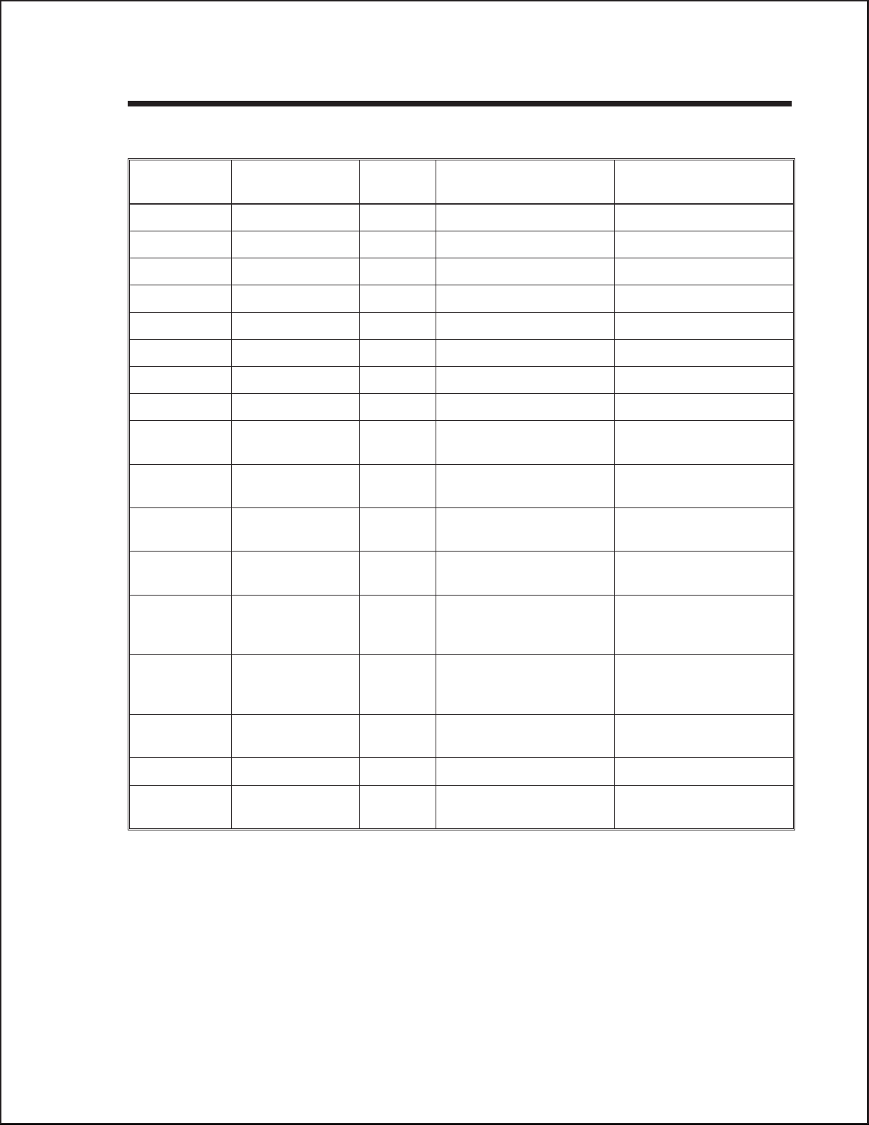
ERROR SIGNALS
Section 6. Troubleshooting
LED LCD
MESSAGE
Error On Machine Error 1 Long Machine Error Cycle power on/off
Error On EEPROM Error 1 Long EEPROM Read/Write Cycle power on/off
Error On Head Error 1 Long Head Cycle power on/off
Error On Sensor Error 3 Short Sensor Cycle power on/off
Error Blinks Card R/W Error 1 Long Memory Card Read/Write Cycle power on/off
Error Blinks Card Low Battery 1 Long Memory Card Battery Low Cycle power on/off
Error Blinks Head Open 3 Short Head Open Close head lever
Error Blinks Cutter Error 3 Short Cutter Cycle power on/off
Error On
Line Blinks
Error On
Line Blinks
Error On
Line Blinks
Error On
Line Blinks
PARITY ERROR 3 Short RS232 Parity Error Cycle power on/off
Overrun Error 3 Short RS232 Overrun Error Cycle power on/off
Framing Error 3 Short RS232 Framing Error Cycle power on/off
Buffer Over 3 Short Buffer Overflow Cycle power on/off
AUDIBLE
BEEP
ERROR CONDITION TO CLEAR
Error Blinks
Label On
Error Blinks
Ribbon On
Error Blinks
Label Blinks
Ribbon Blinks None Ribbon Near End Replace ribbon with full roll
Line Blinks None Buffer Near Full Slow down transmission
Paper End 3 Short Label End Open/close Head Lever
Open/close Label Hold-
down
Ribbon End 3 Short Ribbon End Open/close Head Lever
Open/close Label Hold-
down
Media Error 3 Short Media Error Open/close Head Lever
rate
51
 Loading...