

Panduit NKFD1W6**DSC, NKFD1W12**DSC, NKFD1W12**DLC, NKFD1W24**DLC Installation Instructions Manual
Page 1
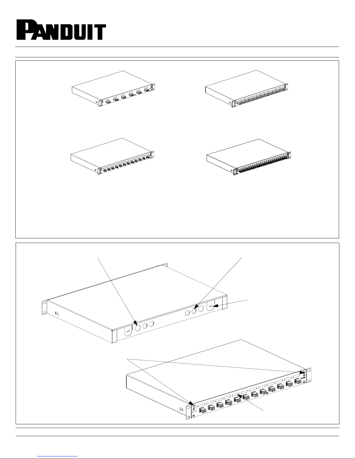
NetKey Pre-Loaded Fiber Drawers
Part Numbers: NKFD1W6**DSC, NKFD1W12**DSC, NKFD1W12**DLC,
NKFD1W24**DLC
© Panduit Corp. 2016
NKFD1W6**DSC
NKFD1W12**DLC
Accessory Kit
(4) #12-24 x 1/2" Screws, (4) M6 Screws, (1) Fiber Caution Label, (1) Laser Warning Label, (2) Slack Spools and (1) PG11 Gland.
** Denotes adapter color/fiber type: EI (Electric Ivory/OM1 62.5/125µm), BL (Black/OM2 50/125µm), AQ (Aqua/OM3 10Gig 50/125µm),
or BU (Blue/OS1/OS2 9/125µm).
INSTALLATION INSTRUCTIONS
NKFD1W12**DSC
NKFD1W24**DLC
FS126
Knockouts for PG11 Glands
(2 places)
20mm Diameter
Drawer Release
Knockouts for Blown Fiber Adapters
(4 places)
Knockouts for Rubber Grommets
(2 places)
30mm Diameter
Latches
Provisions for Port
Identification Labeling
For Technical Support: www.panduit.com/resources/install_maintain.asp
Page 1 of 4
Page 2
© Panduit Corp. 2016
INSTALLATION INSTRUCTIONS
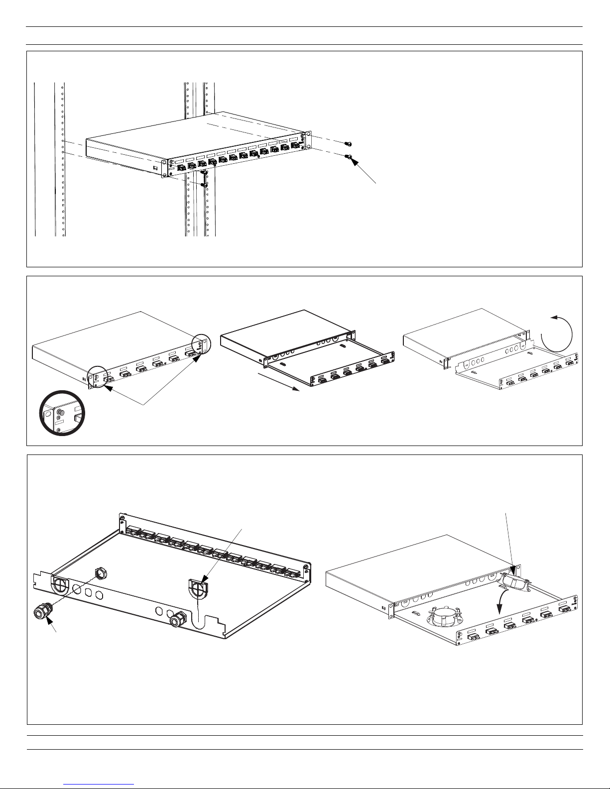
Mounting
Mount the enclosure to rack using four (4) 6mm or #12-24 x 1/2" screws provided.
Drawer Opening and Removal
FS126
6mm or #12-24 x 1/2" screws provided
(4 places)
Release latches
Slide drawer forward Rotate up and remove
Grommet, Gland, and Spool Installation
Rubber Grommet
PG11 Gland
Remove knockouts and insert grommets and/or glands as shown
above.
Spool
Remove the liner from the tape underneath each fiber
management spool. Place the fiber management spools
inside the enclosure as shown above.
Note: Do not install spools if splicing with Fiber Optic Splice
Module (FOSM).
For Technical Support: www.panduit.com/resources/install_maintain.asp
Page 2 of 4
Page 3

© Panduit Corp. 2016
Typical Cable Routing Options
INSTALLATION INSTRUCTIONS
FS126
Grommet with Pre-Terminated Trunk
or Field Termination
PG11 Gland with Pre-Terminated Trunk
or Field Termination
Grommet with splicing using the
FSC24 Splice Sleeve Holder
PG11 Gland with splicing using the
FSC24 Splice Sleeve Holder
For Technical Support: www.panduit.com/resources/install_maintain.asp
Page 3 of 4
Page 4

© Panduit Corp. 2016
INSTALLATION INSTRUCTIONS
FS126
Typical Cable Routing Options (continued)
Blown Fiber with splicing using
the FSC24 Splice Holder
FOSM installation: Place double stick tape underneath
FOSM and locate the FOSM in the enclosure as shown.
Grommet with splicing using the
Fiber Optic Splice Module (FOSM)
PG11 Gland with splicing using the
Fiber Optic Splice Module (FOSM)
Blown Fiber with fusion splicing using the
Fiber Optic Splice Module (FOSM)
For Instructions in Local Languages
and Technical Support:
www.panduit.com/resources/install_maintain.asp
www.panduit.com
Page 4 of 4
E-mail:
techsupport@panduit.com
Phone:
866-405-6654
 Loading...