

Page 1
© Panduit Corp. 2010
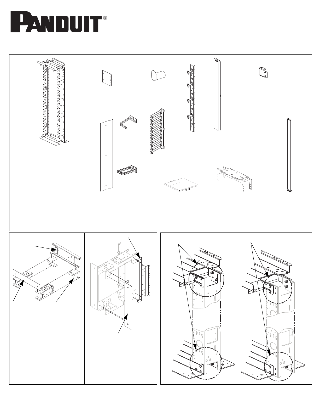
Modular NETFRAME™ Rack and Accessories
Part Numbers: NFR84, NFD484, NFSK, NFDR4X6K, NFCDRK, NFVSM4, NFEDB23,
NFSHLF19X18, NFSHLF19X25, NFLRB, NFEP, NFD884, NFD1284, NFREB2, NFBRFK
INSTRUCTIONS CM281G
Optional Accessories
(2) Rear Extender
Bracket
(8) #12-24 Screws
NFREB2
(1) Spool
(2)#12-24 Screws
NFSK
ETFRAME Extender
(1) N
Door Brackets for
23” Mtg
(4) #10-32 Screws
NFEDB23
NFR84
Modular NETFRAME Rack
(2) Vertical Channels
(2) Base Angles
(1) Pack of (20) 3/8x1.00
Bolt, Lockwasher, Nut
(1) Front Top Flange
(1) Rear Top Flange
(2) Center Waterfalls
(1) Pack of (25) #12-24x1/2” Screws
(1) Grounding and Hardware Kit
Rack Assembly
Front Top
Flange
(16) Center
D-rings
NFCDRK
(8) Bend Radius Fingers
(8) D-rings
NFDR4X6K
(1) End Panel
(6)3/8”-16x1.625” Hex Bolts
3/8”-16 Hex Nuts
3/8” Split Lockwashers
NFEP
Rear Top Flange
NFBRFK
(1) Vertical
Slack Manager
NFVSM4
(1) Shelf
(4) #12-24 Screws
NFSHLF19x18
NFSHLF19x25
(shown)
19” Mounting 23” Mounting
(1) Center
Door, with
brackets
NFD884
NFD1284
(1) Ladder Rack
Bracket
(2)3/8”-16x1” Hex Bolts
3/8”-16 Hex Nuts
3/8” Split Lockwasher
NFLRB
(1) Door, 4” wide w/
Mtg Brackets
(4) #10-32 Screws
NFD484
Base Angle
Step1
Lay the two vertical channels
on the floor or a pair of sturdy
saw horses to ease installation.
Install (1) Base Angle and
Front Top Flange on the vertical channels using (8) 3/8”
bolts, lockwashers and nuts
provided. Do not tighten.
Vertical
Channel
FOR TECHNICAL SUPPORT www.panduit.com/resources/install_maintain.asp
Base Angle
Step 2
Roll the rack on its side to install
the other base angle and rear
top flange using (8) 3/8” bolts,
lockwashers and nuts provided.
Do not tighten.
Page 1 of 4
Page 2
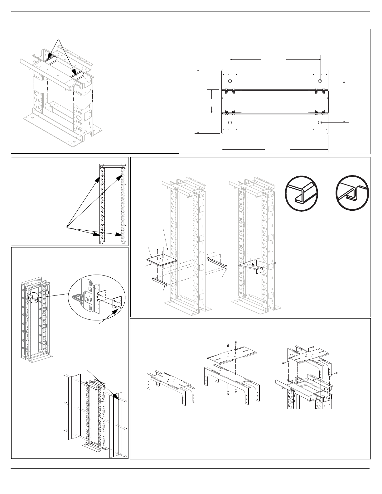
INSTRUCTIONS CM281G
23.875
28.40
11.00
17.00
6.00
Rear
Bracket
Front
Bracket
Shelf
Plate
#10-32 Screws
C Channel
J Slot
Flush
Mount
6 in.
Mount
Center Waterfall
Step 3
Stand the rack upright.Verify
#12-24 tapped holes are EIA
spaced at 18.31”, square the
rack and tighten bolts.
Install the two waterfalls with
the #10-32 screws provided.
Grounding Kit
(1) Barrel Lug
(1) 1/4”-20 Screw
Barrel Lug and
Grounding Screw
mounts to rear of
rack in one of four
optional places.
Rear Extender Bracket Installation
NFREB2
Use (2) #12-24 screws to secure each
bracket in desired location
(2) #12-24
SCREWS
Location Guide: 19” Rack
Mount rack to floor using the location guide below for
mounting hole and overall size information.
Shelf Installation
NFSHLF19X18, NFHSLF19X25
Attach Rear Bracket to rear of
rack at desired height with
#12-24 screws. Attach Front
Bracket to front of rack at
desired height with #12-24
screws. Attach Shelf Plate to
Front and Rear Brackets with
the #10-32 screws. The Shelf
Plate “C” Channel mates with
the bracket “J’ Slot to provide
adjustable mounting. Can be
mounted “flush” or extended 6
inches.
.
Ladder Rack Bracket Installation
NFLRB
End Panel
NFEP
NFEP attaches to
rack with (6) 3/8”16x.625” Hex Bolts,
3/8”-16 Hex Nuts
and 3/8” Split Lockwashers provided.
NFEP
NFLRB Top Plate
attaches to Main
Bracket with (2) 3/8”16x1” hex bolts, 3/8”-16
hex nuts and 3/8” splitlockwashers provided
FOR TECHNICAL SUPPORT www.panduit.com/resources/install_maintain.asp
Page 2 of 4
NFLRB Top Plate
can be assembled
perpendicular to
Main Bracket to
support parallel
runs of ladder rack.
NFLRB assembles to
NFR84 using 3/8”-16x1”
hex bolt, nut, and lockwasher provided with
NFR84
Page 3

INSTRUCTIONS CM281G
D-Rings Installation:
NFDR4X6K
NFDR4x6K
Center D-Rings Installation:
NFCDRK
Right side installa-
tion snaps down
Left side installation
snaps up
Side Mount EIA/NETFRAME Racks
Vertical Slack Manager attaches to your frame with (3) 3/
8” bolts, nuts and lock washers.
NFCDRK
NETFRAME Vertical Slack Manager: NFVSM4
Spool Installation
Step 1
Align buttons with
mounting leg slot
Step 2
Push buttons through backbone until mounting face is
flush with backbone.
Bend Radius Fingers Installation
NFBRFK
Fingers install by snapping (down right side)
(up left side) use (3) #12-24 screws to secure
each finger section in desired location.
Note:
Start finger installation from bottom of rack and
continue upwards on the right side. Start finger
installation from top of rack and continue down
on the left side.
Step 3
Apply downward pressure until plastic spool
clicks into place.
Angled Flange
Removal/Replacement
Step 4
Pull back on angled flange while
applying upward pressure
Step 5
Repeat steps 1-3
FOR TECHNICAL SUPPORT www.panduit.com/resources/install_maintain.asp
Page 3 of 4
Page 4

INSTRUCTIONS CM281G
Door Installation
NFD484
NFEDB23
NFEDB23 installed to
N
ETFRAME Top Flange
with #10-32 screws
provided. To be used
when rack is set-up for
23” mounting
NFD484 installed to NETFRAME with
(4) #10x32 screws provided.
To p
Spool
NFSK
NFSK attaches to
rack with (2) #12-24
screws provided
Center Door
NFD884
NFD1284
Bottom Bracket
1. Use 3/8”-16x1” bolt, 3/8”-16 nut and 3/8” lockwasher provided with NETFRAME to gang two racks
together using NETFRAME junction holes located on side of rack channels.
2. Straddling the two racks, fasten Top Bracket and Bottom Bracket with #10-32x5/16” screws provided.
3. Door installs to top and bottom brackets by aligning lower hinge pin to hinge pin mounting hole.
Squeeze knobs together, then align upper hinge pin to upper hinge pin mounting hole. Release pressure
on knobs to set door in place.
NFD884
For instuctions in Local Languages
and Technical Support:
www.panduit.com/resources/install_maitain.asp
www.panduit.com
Page 4 of 4
E-mail:
cs@panduit.com
Fax
(708)444-6448
 Loading...