

Page 1

Page 2

DD ii ss cc oo vv ee rr
N
ET
F
RAME
™
Rack System
Page 3

Changes to your patch fields instantly triggered an alert message?
•
Any changes were instantly recorded into your patch field database, ensuring
100% accuracy day or night?
•
Network assets could be automatically identified by type and physical
location — Giving you the ability to see what is connected and where?
•
You could graphically look at the whole link — end to end, to eliminate any
uncertainty about any connection?
•
You could electronically plan, prioritize and assign all moves, adds and changes,
document the status of each, guide the technician through the changes using LEDs
on patch panels, record the time needed to complete the task, and automatically
update the database to reflect the new configuration?
•
You could do all this on-site at your management station?
Now you can.
Wouldn't it be great if...
310
Page 4

Introducing the PANVIEW
™
Physical Layer
Management System
Structured Cabling is the foundation of your
network and patch fields are the heart of
your structured cabling system. A single
patch cord disconnection can bring critical
segments of the network down, provide an
unimpeded source for a breach in network
security or decrease the efficiency of the
network exponentially. Without an on-line
physical layer management system, those
same patch fields are virtually invisible in your
network management system.
The
PANVIEW
system, through its innovative use
of scanners, enabled patch panels, reliable
patch cords and software, provides real-time
monitoring of physical layer connectivity. This
system provides networks with greater
reliability, improved security, better efficiency
and greater savings. From financial firms to
logistic and manufacturing firms, network
reliability is essential. This system with its
capabilities of monitoring and protecting
these connections 24 hours a day, 7 days a
week, 365 days a year, is a must. The
PANVIEW
system not only meets these criteria, it takes
network management to the next level by
providing the accurate, real-time information
necessary to manage the physical layer in
today's world.
Real-Time and Real-
Network Reliability, Security and
Efficiency.
Network Reliability, Security and
Efficiency.
Page 5
PHYSICAL LAYER MANAGEMENT SYSTEM
The
PAN
VIEW
™
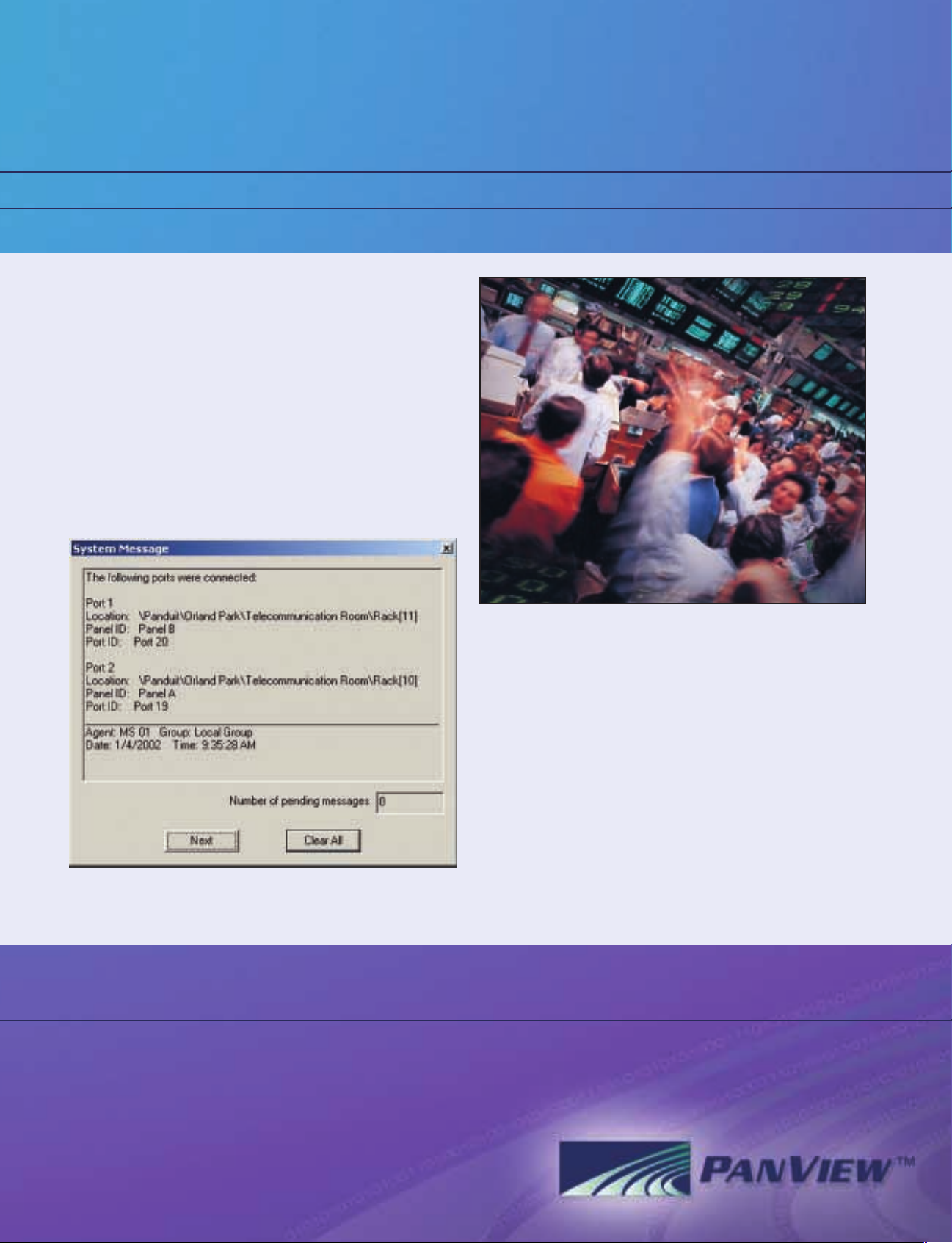
system, through its continuous scanning
process, provides the user with real-time end-to-end
documentation of their physical layer. Movement of a
patch cord instantaneously triggers an alert message
at the management station. However, the
P
ANVIEW
system takes reliability a step further by ensuring that
your patch field database is 100% accurate day or
night. The continuous scanning process in the
PANVIEW
system allows the management software to
continually verify the accuracy of the database,
providing the user with a real-time picture of the patch
field.
Today’s networks handle millions of bytes of sensitive
information everyday. Whether it is information
pertaining to a large financial transaction a company
is making or an individual customer placing an order,
confidentiality and security is imperative. Using the
PANVIEW
system helps improve your network security.
The most powerful way to improve network security is
through the
P
ANMAP
™
module, which uses leading
edge technology to identify and track asset
movement throughout the network. It then shows
these assets in the appropriate locations within the
database — giving the user the ability to see what is
connected and where.
Reliability Security
58
Page 6

The Link Module allows the administrator to graphically
view the entire link from the management station. It
also allows for changes to be made to any link in the
system with just a few clicks of the mouse button.
With the Work Order Module, the Network
Administrator can plan, prioritize, and assign all of the
moves, adds, and changes in the system. The system
then documents the status of the work order, guides
the technician through the changes using LEDs on the
patch panels, records the time needed to complete
the task, and automatically updates the database to
reflect the new configuration.
Efficiency
Link Module
Link Module
Work Order Module
Work Order Module
Responding quickly and efficiently to user requests for service changes is often a
challenge. Network Administrators and Technicians spend significant amounts of
time planning and executing the process. Even then, mistakes happen. The wrong
patch cord is accidentally disconnected or the right cord ends up in the wrong port
causing even greater confusion. The
PANVIEW
™
system eliminates this problem with two
software modules, the Link Module and the Work Order Module.
Page 7
Network assets, from switches and patch panels to
computers and software, are expensive. Making sure
that your system optimizes the use of these assets can
be a formidable task. Quite often it is easier to
purchase a new piece of equipment than it is to
reclaim an existing one.
The
PANVIEW
™
system solves this by keeping a database
of switch port usage. The system makes reclaiming
network capacity as simple as the click of a few
buttons. And if your system approaches a capacity
limitation,
PAN
VIEW
's Utilization Report provides
complete details.
The
PAN
VIEW
system provides invaluable benefits for
customer networks in the form of greater reliability,
improved security and better efficiency. A customer
specific return on investment (ROI) model provides
step-by-step guidance to answering these questions.
Savings Value
PHYSICAL LAYER MANAGEMENT SYSTEM
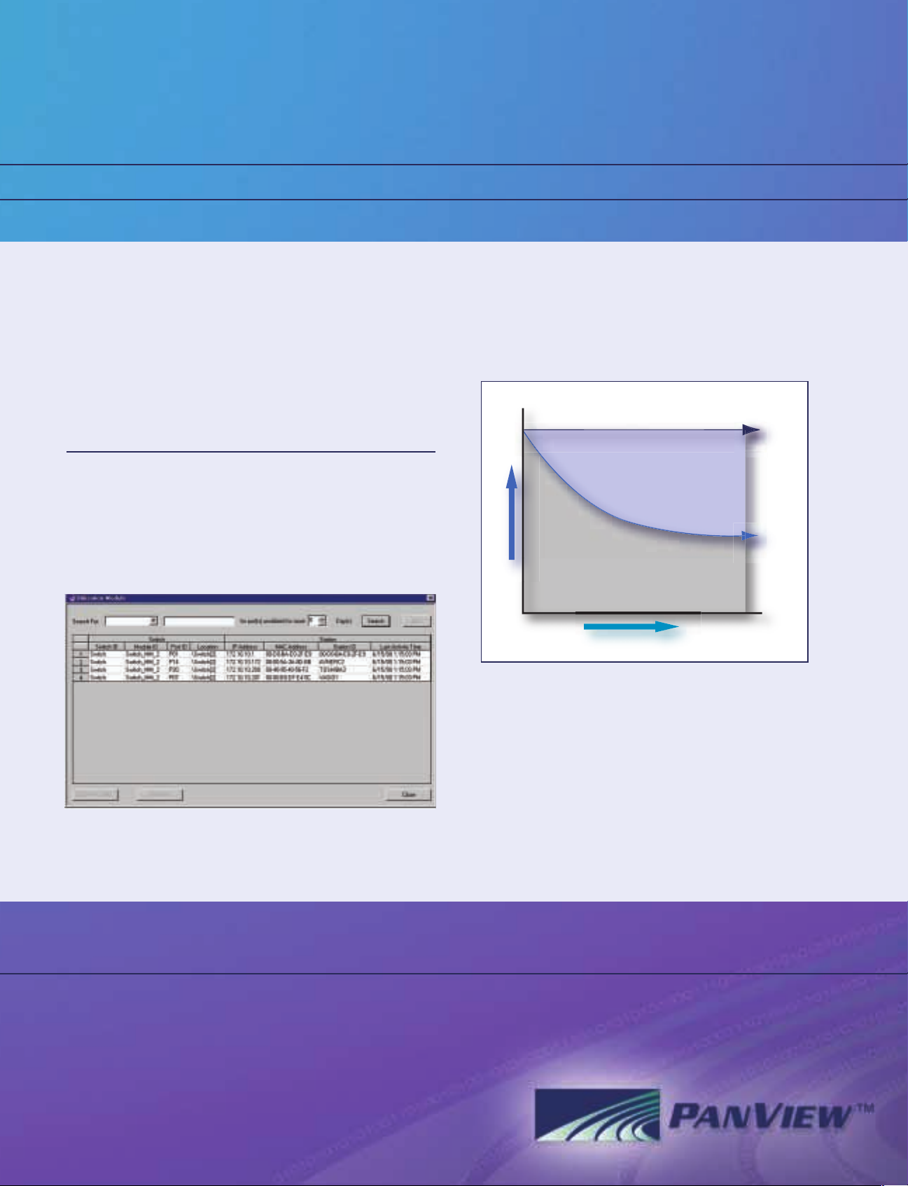
Utilization Module
Utilization Module
Normal Network Asset Utilization
over time
Network
Operations
with
PANVIEW
100%
Network
Operations
without
PANVIEW
Life of the Network (years)
Network Asset Savings
generated by
PANVIEW
Network Equipment
Network Asset Utilization
For feasibility study assistance contact
PANDUIT
®
at 866-405-6654.
76
Page 8

The
PANVIEW
software is based on client/server
architecture, and provides valuable information in an
easy to use format. The software ensures the
information is 100% accurate by automatically
updating the database whenever there is a
connectivity change. It has several different modules
that allow single user changes or complete
department moves with just a few clicks. In addition,
the software provides seamless integration into select
network management programs, documents asset
utilization, and tracks the movement of network assets
using the
PANMAP
™
module.
P
ANVIEW
electronic scanners are the connectivity data
collectors of the
PANVIEW
system. The scanners monitor
on-site patch panel connectivity, and provide realtime information on the status of all network
connections monitored by the system. The
PANVIEW
system includes both Master and Satellite Scanners.
Scanners are mounted in racks in the
telecommunication room at various sites adjacent to
enabled patch panels.
PANVIEW
Enabled Patch Panels perfor m two functions
in the telecommunications room. Their primary
facilitates data transfer throughout the network.
However, by adding a circuit board and an additional
connectivity point to the panel design; they become
an integral component of the
PANVIEW
physical layer
management system.
Each patch panel is connected to the scanner through
an attachment cord. This cord allows the scanner to
transmit and monitor the status of the connectivity. An
additional contact in the
PANVIEW
patch cord plug
provides the connection to close the loop between
connected ports making a complete circuit for the
scanners to monitor. The scanners then collect all the
connectivity information and report it over the LAN to
the network management station running the
PANVIEW
software. There are LEDs above each patch panel port
that guide the technician through patch cord
changes. A blinking LED indicates that the patch cord
should be disconnected, while a solid LED indicates
that the patch cord should be connected.
The Accessory Controller enables the
PANVIEW
Management Station to monitor the status of various
sensors and activate remote-controlled devices. A
change in status to any of the connected sensors (e.g.
temperature) is immediately noted and sent to the
PANVIEW
Management Station through the Accessory
Controller. The control pad is a portable handheld
device that is connected to the first scanner in each
room. It allows the person performing the MAC to
begin the process under the guidance of the LEDs
above each port.
II. PANVIEW Scanners
II. P
ANVIEW Scanners
System Components
••
Software • Scanners • Enabled Patch Panels
I. Software
I. Software
III. Enabled Patch Panels,
P
ANVIEW Patch Cords
and Accessories
III. Enabled Patch Panels,
P
ANVIEW Patch Cords
and Accessories
Page 9

PHYSICAL LAYER MANAGEMENT SYSTEM
I. Software
Switch
Work Station
II. ScannersIII. Enabled Patch Panels and
PANVIEW
™
Patch Cords
94
Page 10

PAN
VIEW
™
Scanners
PANVIEW Patch Panels
PVMSO
PVSSO
PVEDP246B
PART NUMBER DESCRIPTION
STD.
PKG.
QTY.
NO. OF
RACK
SPACES^
STD.
CTN.
QTY.
PVMSO Master Scanner 2 1 1
PVMSEO Master Scanner with extended memory 2 1 1
PVSSO Satellite Scanner 1 1 1
PVSSEO Satellite Scanner with extended memory 1 1 1
P
ANVIEW Patch Cords
PART NUMBER DESCRIPTION
STD.
PKG.
QTY.
COLORLENGTH
STD.
CTN.
QTY.
PVUTPCTG3BBU Cat 6 UTP patch cord 3 ft. Blue 1 10
PVUTPCTG5BBU 5 ft. Blue 1 10
PVUTPCTG7BBU 7 ft. Blue 1 10
PVUTPCTG9BBU 9 ft. Blue 1 10
PVUTPCTG14BBU 14 ft. Blue 1 10
PVUTPCTG20BBU 20 f t. Blue 1 10
PART NUMBER DESCRIPTION
STD.
PKG.
QTY.
NO. OF
RACK
SPACES^
STD.
CTN.
QTY.
^ One rack space = 1.75" (44.45mm)
^ One rack space = 1.75" (44.45mm)
PVUTPCTG7BBU
PVEDP246B Cat 6 24 port UTP patch panel 1 1 1
Page 11

Software Version
1.0
PVCP
PVSCP
PVACSC
P
ANVIEW
™
Accessories
PART NUMBER DESCRIPTION
STD.
PKG.
QTY.
NO. OF
RACK
SPACES^
STD.
CTN.
QTY.
PVACSC Rack Mount Accessory Controller 1 1 1
PVCP Control Pad — 1 1
PVFACB1.5M 1.5 meter Attachment Cord — 1 10
PVFACB2.5M 2.5 meter Attachment Cord — 1 10
CORD-S* US Power Cord — 1 1
(one required per scanner)
^ One rack space = 1.75" (44.45mm)
* International power cords are also available.
PANVIEW Software
PART NUMBER DESCRIPTION
STD.
PKG.
QTY.
FORMAT
STD.
CTN.
QTY.
PVSCP
P
ANVIEW
Core Software CD ROM 1 1
PVSAMM
PANVIEW
Asset Management Software CD ROM 1 1
PVSWOM
PANVIEW
Work Order Module CD ROM 1 1
PVSAUC
PANVIEW
Core Software Additional User CD ROM 1 1
PVSAUWOM
PANVIEW
Work Order Module Additional CD ROM 1 1
User
For installation design and technical assistance contact
PANDUIT
®
at 866-405-6654
or your authorized
PANVIEW
Systems Integrator.
PHYSICAL LAYER MANAGEMENT SYSTEM
112
Page 12

Copyright © 2002
PANDUIT
Corp. All rights reserved. Printed in the U.S.A.
SA-NC07BR01A
™
NETWORK CONNECTIVITY GROUP
PANDUIT
NETWORK CONNECTIVITY GROUP. The information contained in this literature is based on our experience to date and is believed to be reliable. It
is intended as a guide for use by persons having technical skill at their own discretion and risk. We do not guarantee favorable results or assume any liability in
connection with its use. Dimensions contained herein are for reference purposes only. For specific dimensional requirements consult the factory. This publication
is not to be taken as a license to operate under, or a recommendation to infringe any existing patents. This supersedes and voids all previous literature, etc.
PANDUIT
®
Corp.
(Worldwide HQ)
17301 Ridgeland Avenue
Tinley Park, Illinois 60477-3091, USA
Telephone +1 708 532 1800
Fax +1 708 532 1811
PANDUIT
Corp.
(Network Connectivity Group HQ)
10500 West 167th Street
Orland Park, Illinois 60467, USA
Telephone +1 708 460 1800
Fax +1 708 460 9211
PANDUIT
Europe Ltd
(EMEA HQ)
West World, Westgate
London W5 1XP, United Kingdom
Telephone +44 (0) 208 601 7200
Fax +44 (0) 208 601 7319
PANDUIT
Australia
(National Office)
30-36 Kitchen Road, Dandenong
Victoria 3175, Australia
Telephone +61 (0) 3 9794 9020
Fax +61 3 9794 7101
PANDUIT
Corp.
(Japan Branch)
31-5, Omori-Kita, 6-Chome Ota-Ku
Tokyo, Japan 143-0016
Telephone +81 3 3767 7011
Fax +81 3 3767 7033
PANDUIT
Mexico
(Guadalajara Corp. Offices)
Ave. Lazaro Cardenas 2785
Col. Alamo Industrial, Tlaquepaque
Jal 44490, Mexico
Telephone +52 3 666 2501
Fax +52 3 666 2510
PANDUIT
Asia Pacific Pte Ltd
60 Tuas Avenue 11, Singapore
Republic of Singapore 639106
Telephone +65 379 6700
Fax +65 379 6759
PANDUIT
Canada
140 Amber Street, Markham
Ontario, Canada L3R 3J8
Telephone +1 905 475 6922
Fax +1 905 475 6998
 Loading...