

Panduit NET-ACCESS N21SPH, NET-ACCESS N51SPH, NET-ACCESS N22SPH, NET-ACCESS N52SPH Instructions Manual
Page 1
NET-A
(Split/Hinged Side Panels - N21SPH, N22SPH, N51SPH, N52SPH
© Panduit Corp. 2012
CCESS
INSTRUCTIONS CM606
N-Type Network Cabinets
)
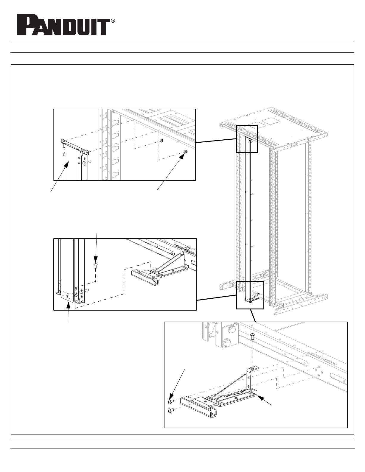
Split/Hinged Side Panels Installation
• VIEW 3 Secure Bottom Support Bracket to cabinet frame with [3] M5 Torx Screws
• VIEW 1, 2 Secure Vertical Support Bracket to cabinet frame and bottom support bracket with [1] M5 Torx Screw and [2] Hex Nuts
• See Page 2 for Side Panel Installation Instructions
VIEW 1
Vertical Support Bracket
(Top)
Vertical Support Bracket
(Bottom)
[2] Hex Nuts
(use 6mm Socket
Wrench)
[1] M5 Torx Screw
(use T25 Torx bit)
VIEW 2
[3] M5 Torx Screws
(use T25 Torx bit)
Bottom Support Bracket
(Part of bracket cut away to
VIEW 3
FOR TECHNICAL SUPPORT www.panduit.com/resources/install_maintain.asp
Page 1 of 2
show detail)
Page 2

INSTRUCTIONS CM606
Split/Hinged Side Panels Installation
• Open Side Panel to approximately 90º
• VIEW 1 Lift Top Hinge Point of Side Panel onto top pin of Vertical Support Bracket
• VIEW 2 Lower Bottom Hinge Point of Side Panel onto bottom pin of Vertical Support Bracket
• VIEW 3 Close Side Panel and secure top and bottom of Side Panel to cabinet frame with [2] Spring Loaded Hinge Pins
VIEW 1
Lift Top Hinge Point of Side Panel onto Top
Pin of Vertical Support Bracket
VIEW 3
Lower Bottom Hinge Point of Side Panel onto Bot-
tom Pin of Vertical Support Bracket
For Instructions in Local Languages
and Technical Support:
www.panduit.com/resources/install_maintain.asp
VIEW 2
www.panduit.com
Page 2 of 2
Spring Loaded Hinge Pin
(Top and Bottom)
Hold Hinge Pin Open
E-mail:
techsupport@panduit.com
Phone:
866-405-6654
 Loading...