

Panduit NET-ACCESS CN3, NET-ACCESS CN7018-EXT, NET-ACCESS CNAE7018, NET-ACCESS CNPS7018 Instructions Manual
Page 1
© Panduit Corp. 2008
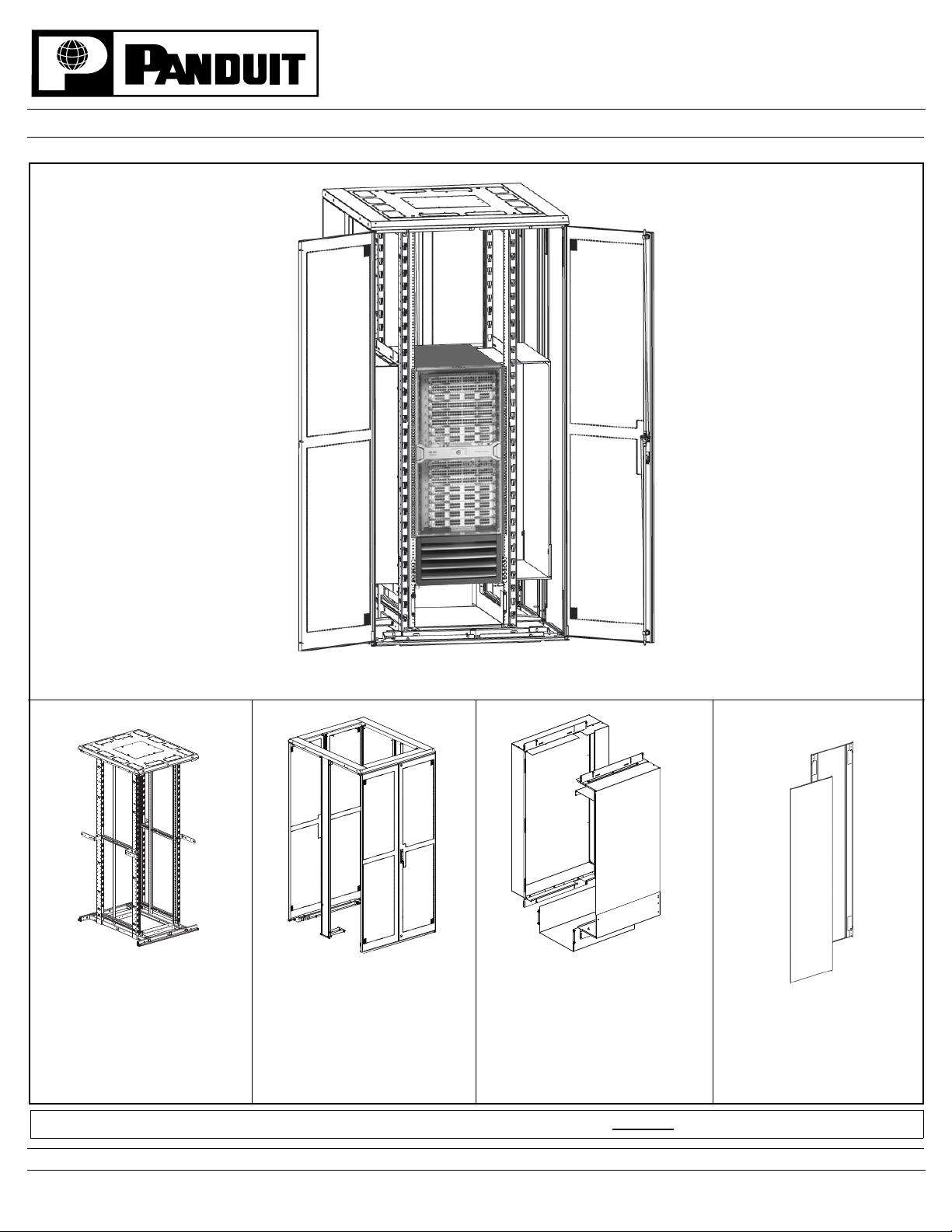
NET-ACCESS Cabinet for Cisco Nexus 7018 Switch
INSTRUCTIONS CM385
Component Guide
CN3
(1) Base Cabinet
(2) Cable Management Finger Kits
(1) Hardware Kit
(2) #12-24 Threaded Equipment Rail Sets
(2) Top Side Extensions
(2) Top Front/Rear Extensions
(2) Bottom Door Shoe Extensions
(2) Bottom Side Extensions
(2) Split Door Sets
(2) Vertical Side Supports
(1) Hardware Kit
For installation instructions for the CN3 cabinet, please reference
CN7018-EXT
CNAE7018
(1) Inlet Duct Assembly
(1) Exhaust Duct Assembly
(1) Bottom Duct Assembly
(5) Mounting Brackets
(1) Hardware Kit
instruction sheet CM317B.
CNPS7018
(2) Side Panels
(2) Lower Horizontal Supports
FOR TECHNICAL SUPPORT www.panduit.com/resources/install_maintain.asp
Page 1 of 8
Page 2
INSTRUCTIONS CM385
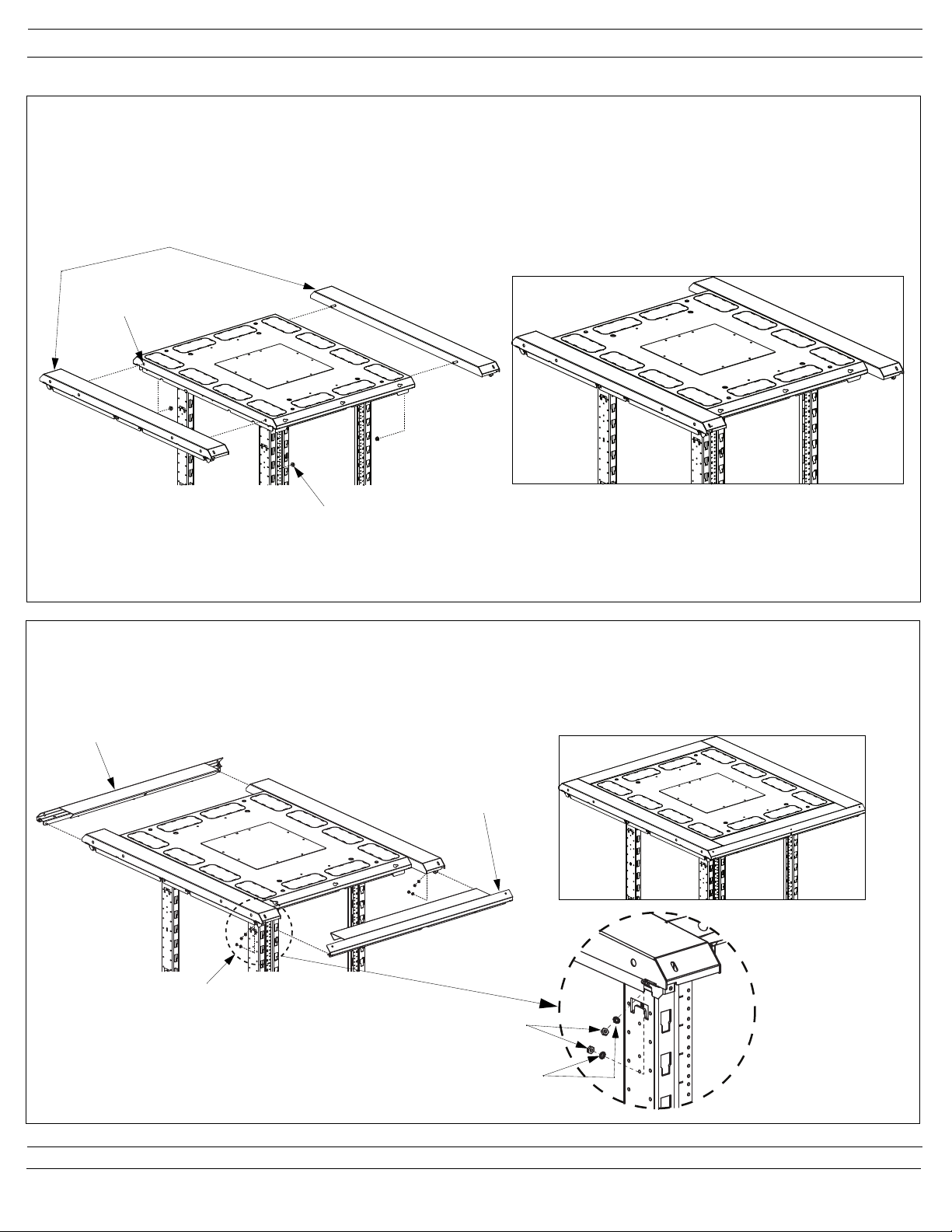
Top Cap Extension Assembly
Installation of Top Side Extensions
Install (2) top side extensions, using (2) 5/16” serrated flange lock nuts on each extension (there are pre-installed 5/16” press-studs in side
extensions). Remove knock-out feature from original top cap if necessary. Do not tighten side extensions until front and rear extensions are
mounted and aligned with original top cap. Top front and back extension installation is shown at the bottom of this page.
Side Extensions
Assembled
Remove Knock-outs
(if necessary)
5/16” Serrated Flange
Lock Nut
Installation of Top Front and Back Extensions
Attach (2) top front and rear extensions, using (4) #10-32 nuts and (4) #10 lockwashers per extension piece (there are (4) pre-installed #10
press-studs in each extension). Align all top extension parts, leaving a minimal gap between side and front/rear parts. Secure side extensions
by tightening (4) 5/16” serrated flange lock nuts.
Rear Extension
Front Extension
Assembled
See Detail View
#10-32 Nut
#10 Lockwasher
For Technical Support: www.panduit.com/resources/install_maintain.asp
Page 2 of 8
Page 3
INSTRUCTIONS CM385
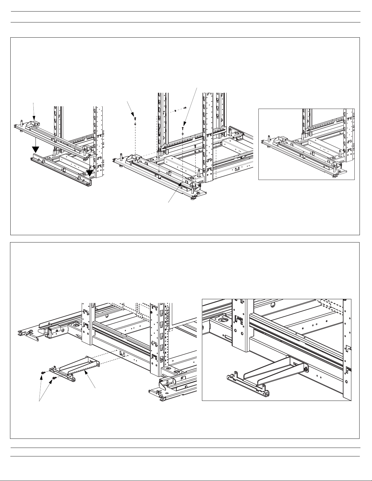
Door Shoe Extension Assembly
Installation of Front and Back Bottom Door Shoe Extensions
Install (2) door shoe extensions to existing cabinet door shoes using (6) #12-24 pan head phillips screws on each side and (6) #12 lockwashers;
(4) screws vertical on front and (2) screws horizontal from behind. Center extension by installing a screw through the centering hole first,
followed by installing the remaining screws through slots as shown.
#12-24 pan head
Door Shoe
Extension
Existing Cabinet
Door Shoe
phillips screws and
#12 lockwashers
Installation of Bottom Side Extensions
Centering Screw
Assembled
Centering Hole
Install (2) bottom side extensions as shown. Secure using (2) #12-24 serrated hex head screws on each extension.
Assembled
Bottom Side
Extension
#12-24 serrated
hex head screws
For Technical Support: www.panduit.com/resources/install_maintain.asp
Page 3 of 8
Page 4

INSTRUCTIONS CM385
Exhaust Duct Installation
Install (2) universal ducting brackets on the top and bottom surfaces of the exhaust duct using (6) #10-32 pan head phillips screws and
(6) #10 lockwashers. Mount duct assembly to cabinet posts using (7) #12-24 serrated hex head screws through ducting brackets and slotted
flange as shown. The top flange of duct assembly should be positioned above the top surface of switch.
See Detail View
Exhaust Duct
#10-32 Pan Head
Phillips Screws
#10 Lockwashers
Universal Ducting
Bracket
Assembled
#12-24 serrated
hex head screws
For Technical Support: www.panduit.com/resources/install_maintain.asp
Page 4 of 8
Page 5

INSTRUCTIONS CM385
Inlet Duct and Bottom Duct Installation
Install (2) universal ducting brackets on the top and bottom surfaces of the inlet duct using (6) #10-32 pan head phillips screws and
(6) #10 lockwashers. Mount inlet duct assembly to cabinet posts using (4) #12-24 serrated hex head screws through ducting brackets as
shown. The top flange of duct assembly should be positioned above the top surface of switch. Mount bottom duct to equipment rails using
(4) #12-24 serrated hex head screws as shown. Attach rear mounting bracket to bottom duct using (2) #10-32 hex nuts and (2) #10 lockwashers
(there are (2) pre-installed press studs on the bottom duct. Secure the bracket to rear equipment rails using (2) #12-24 serrated hex head
screws as shown.
NOTE: if using bottom duct, loosen (2) wing nuts inside inlet duct assembly and fully extend the bottom flange. Mount inlet duct assembly to
cabinet posts in the same manner listed above.
#10-32 Pan Head
Phillips Screws
#10 Lockwashers
Universal Ducting
Bracket
Inlet Duct
#12-24 serrated
hex head screws
Extend inlet duct
when also using
bottom duct
Bottom Duct
#12-24 serrated
hex head screws
REAR OF CABINET
Rear Mounting
Bracket
#10-32 hex nuts and
#10 lockwashers
Assembled
#12-24 serrated
hex head screws
For Technical Support: www.panduit.com/resources/install_maintain.asp
Page 5 of 8
Page 6

INSTRUCTIONS CM385
Vertical Side Support Installation
Mount (2) vertical side supports using (4) #10-32 nuts per post; (2) at top and (2) at bottom (there are (4) pre-installed press studs in each post).
Assembled
Vertical Side Supports
#10 Lockwashers
#10-32 Nuts
For Technical Support: www.panduit.com/resources/install_maintain.asp
Page 6 of 8
Page 7

INSTRUCTIONS CM385
Side Panel Installation
Installation of Lower Horizontal Supports
Mount (4) lower horizontal supports, using (2) #10-32 flat head screws and (2) #10 lockwashers (at bottom side extension) and (1) 1/4-20 hex
head screw (at door shoe extension) per lower horizontal support as shown.
1/4-20 Hex Head Screw
#10-32 Flat Head Screws
and #10 Lockwashers
1/4-20 Hex Head Screw
#10-32 Flat Head Screws
and #10 Lockwashers
Lower Horizontal Supports
Installation of Side Panels and Split Doors
Side Panels
Pull down the lever of the top spring loaded hinge pin and lock into
position. Lift side panel and align bottom pin with the hinge point in the
lower horizontal support. Swing door up and align pin with the hinge
point in top cap extension. Release locked hinge pin lever. Pull
and lock remaining spring loaded hinge pins and move side panel into
position. Release levers when aligned. Reverse steps to remove side
panels.
Hinge Pin
Unlocked Position
Top Spring
Loaded Hinge Pin
Assembled
Split Doors
Lift split door and align fixed hinge pin with the bushing in the bottom
door shoe extension. Swing door up and pull down the lever of the
spring loaded hinge pin and align pin with the bushing in top cap
extension. Release lever when aligned. Reverse steps to remove door.
Spring Loaded
Hinge Pin
Bottom Spring
Loaded Hinge Pin
Hinge Pin
Locked Position
Fixed Hinge Pin
For Technical Support: www.panduit.com/resources/install_maintain.asp
Page 7 of 8
Page 8

INSTRUCTIONS CM385
Adjustment of Side Panel
Adjust side panels by loosening the (2) hex head screws securing the bottom side extension to the cabinet frame as shown. Reposition the
bottom side extension as necessary. Tighten the (2) hex head screws.
See Detail View
Loosen these
screws
Reposition
Bottom Side
Extension as
necessary
For Instructions in Local Languages
and Technical Support:
www.panduit.com/resources/install_maintain.asp
www.panduit.com
Page 8 of 8
E-mail:
cs@panduit.com
Fax:
(708)444-6448
 Loading...