

Page 1
INSTALLATION INSTRUCTIONS CM296A
© Panduit Corp. 2004
For Technical Support: www.panduit .com/resources/install_maintain.asp
Industrial Automation Enclosure
Part Number: IAEIP66, IAEFK54
Page 1 of 5
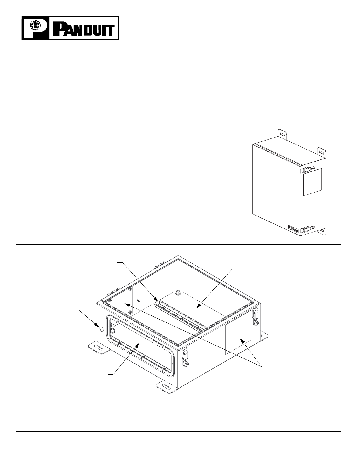
(view shown with door removed)
List of Components:
(1) 24 VDC Power Supply
(3) T
AK-TYS
(6) Adhesive Backed Mounts
(6) P
AN-TYS
(1) Electrical Hole Se al
(1) Port ID Label
(3) 10 AWG Grounding Cables
(1) 12 AWG Grounding Cable
(1) 35mm DIN Rail
(1) #10-32 x 1/2" Pan Head Screw
(3) #10 Spring Lock Washer
(2) #10-32 Hex Nut
IAEIP66
35mm DIN Rail
Cover Plates for Fan
and Exhaust Filter
Openings
Opening for 1/2"
Conduit Fitting
Opening for Industrial
Enclosure Gland Plate
Inner Panel
Important Notice:
Should Fan Kit P/N IAEFK54 be integrated into the enclosure, P/N IAEIP66, the IP rating of the enclosure
shall be reduced to IP54. If the enclosure and any active equipment is located in an environment containing conductive
particles that have the potential to cause sparks and shorts, or the enclosure is placed in an environment that contains
ignitable dust or explosive gases, in this scenario the IP rating of the enclosure shall be reduced to IP44. Before any
application in these last cases, the installer should insure that all requirements, legal and industry, are met and
precautions are taken to meet the installation requirements of the equipment placed inside the enclosure.
Page 2
INSTALLATION INSTRUCTIONS CM296A
For Technical Support: www.panduit .com/resources/install_maintain.asp
(8) #10 Split Lock Washers
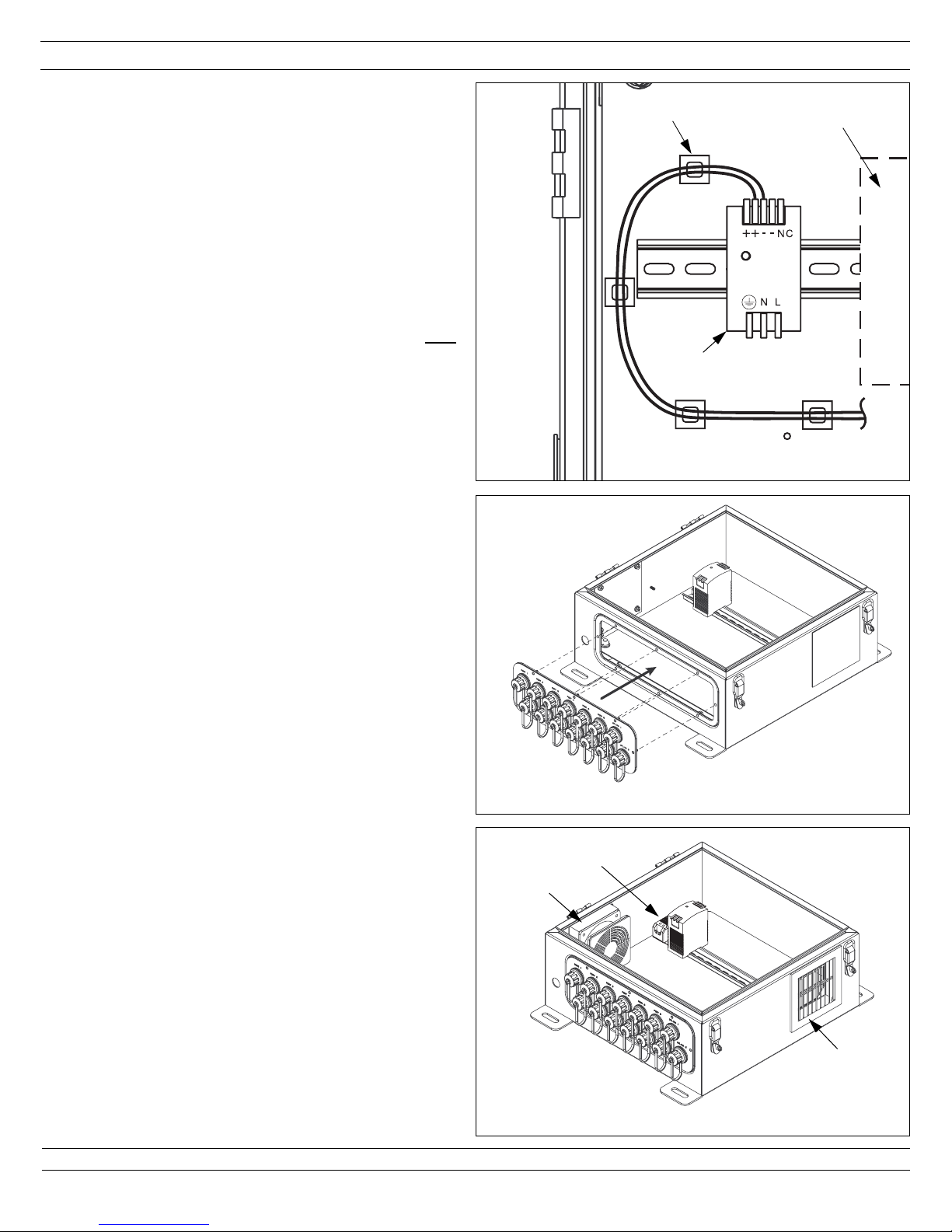
Step 1: Power Supply Installation
1.1 Install the 24 VDC Power Supply to the 35mm DIN rail.
Refer to the power supply instruction sheet for proper
wiring techniques and safety.
1.2 Run a lead from the inside "+" position on the output
side of the power supply to the switch.
1.3 Run a lead from the inside "-" position on the output
side of the power supply to the switch.
1.4 Terminate the leads to the switch per the instructions
provided by the switch manufacturer.
Note: Verify the switch being installed is 24 VDC.
1.5 If installing the optional fan, complete the following after
the fan has been installed and wired.
Use the Adhesive Backed Mounts and P
AN-TYS to
manage the wires and secure them to the inner panel.
Save a couple adhesive mounts and P
AN-T YS to
manage and secure the incoming power lines to the
inner panel.
Note: Refer to figure 1 for an example of how the wires
can be routed.
Power
Supply
1
Area for Switch
Adhesive Mount
2
(Previously installed cables removed from view for clarity)
2.1 Insert the studs of the gland plate through the holes
on the enclosure.
2.2 Verify the gland gasket is flat and positioned evenly
between the plate and the enclosure.
2.3 Secure the plate to the enclosure using the supplied
#10 Flat Washers, #10 Split Lock Washers and #1032 Nuts. Torque the nuts to 5 in-lbs.
Step 2: Gland Plate Installation (sold separately)
PANDUIT Part #’s:
IAECGP - Industrial Automation Enclosure Connector Gland Plate
IAEBGP - Industrial Automation Enclosure Blank Gland Plate
Page 2 of 5
3.1 Remove the cover plates from the enclosure.
3.2 Snap the IP54 Fan from the outside into the bottom
opening near the gland plate. Make sure the louvers
are angled toward the bottom of the enclosure.
3.3 Snap the IP54 Exhaust Filter from the outside into the
top opening of the enclosure. Make sure the louvers
are angled toward the bottom of the enclosure.
3.4 Install the Thermostat to the DIN rail of the enclosure.
Step 3: Optional Fan Kit Installation (sold separately)
PANDUIT Part #:
IAEFK54 - Industrial Automation Enclosure Fan Kit
3
Fan
Exhaust
Filter
Thermostat
(Previously installed cables removed from view for clarity)
(1) Gland Pl ate
(1) Gland Plate Gasket
(14) IP67 Bulkheads
(14) Patch Cords
(1) Blank Gland Plate
(1) IP54 Fan
(1) IP54 Exhaust Filter
(1) Thermostat
(8) #10-32 Nuts
(8) #10 Flat Washers
(1) Gland Plate Gasket
(8) #10 Flat Washers
(8) #10 Split Lock Washers
(8) #10-32 Nuts
Page 3

INSTALLATION INSTRUCTIONS CM296A
For Technical Support: www.panduit .com/resources/install_maintain.asp
Page 3 of 5
4
4.1 Refer to the power supply instruction sheet for proper
wiring techniques and safety.
4.2 Run a lead from the outside "+" position on the output
side of the power supply to the 1 position of the
thermostat.
4.3 Run the positive lead of the fan to the 2 position of the
thermostat.
4.4 Run the negative lead of the fan to the outside " -"
position on the output side of the power supply.
4.5 Use the adhesive mounts and P
AN-TYS to manage the
wires and secure them to the inner panel. Save a
couple adhesive mounts and P
AN-TYS to manage and
secure the incoming power lines to the inner panel.
Step 4: Wiring Optional Thermostat and Fan
5.1 Refer to the power supply instruction sheet for proper
wiring techniques and safety. If the power supply is not
being connected to the incoming power at this time,
cover the hole using the provided Electrical Hole Seal.
5.2 Connect the hot wire to the "L" on the input side of the
power supply.
5.3 Connect the neutral wire to the "N" on the input side of
the power supply.
5
Step 5: Wiring the Input Side of Power Supply
Page 4

INSTALLATION INSTRUCTIONS CM296A
For Technical Support: www.panduit .com/resources/install_maintain.asp
Page 4 of 5
6A
(Previously installed cables removed from view for clarity)
BaseDoor
10 AWG
Ground Cable
Incoming
Ground Cable
6.1 Connect the incoming ground cable to the ground stud
on the base of the enclosure. Use the remaining
adhesive mounts to manage and secure the hot wire,
neutral wire and incoming ground cable to the inner
panel.
6.2 Using one of the supplied 10 AWG Grounding Cables,
attach one end to the grounding stud on the base, on
top of the incoming ground, and the other end to the
grounding stud on the door.
6.3 A second 10 AWG Grounding Cable is to be attached to
the grounding stud on the base, on top of the other two
cables, and the other end will be secured to the inner
panel as shown in Figure 6B.
6.4 Secure the cable ends to the grounding studs on the
base and the door using the supplied #10 Spring Lock
Washers and #10-32 Hex Nuts.
6.5 The third 10 AWG Grounding Cable is to be attached to
the grounding position on the switch and the other end
will be secured to the inner panel.
6.6 The 12 AWG Grounding Cable is to be attached to the
power supply and the inner panel. The end without a
terminal should be attached to the power supply. Refer
to the power supply instruction sheet for proper wiring
techniques and safety.
6.7 Secure the three grounding cables (base, switch and
power supply) to the inner panel using the supplied
#10-32 x 1/2" Pan Head Screw and #10 Spring Lock
Washer.
Step 6: Grounding Cable Installation
6B
10 AWG
Ground
Cable
Inner Panel
12 AWG
Ground
Cable
10 AWG
Ground
Cable
Secure
Cables
Here
Page 5

INSTALLATION INSTRUCTIONS CM296A
E-mail:
cs@panduit.com
Fax:
(708) 444-6993
For Instructions in Local Languages
and Technical Support:
www.panduit.com/resources/install_maintain.asp
www.panduit.com
Page 5 of 5
7.1 Insert the connector end of the patch cord into an IP67
bulkhead.
7.2 Insert the plug end of the patch cord into the
corresponding port on the switch.
7.3 Insert the provided T
AK-TYS through the shear forms on
the inner panel to manage and secure the patch cords
within the enclosure.
Step 7: Patch Cord Installation
7
Patch
Cord
TAK-TY
(Switch)
 Loading...