

Page 1
SmartZone™ Gateway EPA126
Firmware v.2.04.xx
User Manual
IM011
Release 1.0
Issue 1
Page 2

SmartZone Gateway EPA126 User Manual
SmartZone Gateway EPA126 User Manual
Copyright © 2017 Panduit Corp. All rights reserved. No part of this book shallbe reproduced, stored in a retrieval system, or transmitted
by any means, electronic, mechanical, photocopying, recording or otherwise, without written permission from Panduit. No patent liability
is assumed with r espect to the use of the information contained herein.
Although every precaution has been taken in the preparation of thisbook, Panduit assumes no responsibilityfor errors or omissions.
Neither is any liabilityassumed for damages resulting from the use of the information contained herein.
- 2 -
Page 3

SmartZone Gateway EPA126 User Manual
Table of Contents
Introduction 8
Remote Temperature and Humidity Sensing 8
PDU Monitoring 8
EPA126 Package 9
Front of Gateway EPA126 9
LEDs 9
Network 9
Status 9
Power 10
Buttons 10
Back of Gateway EPA126 10
Output Relays 11
Installation Requirements 12
Rack Mounting 12
Equipment Required 12
Before You Begin 12
Installation Warning Statements 12
Rack-Mount the EPA126 13
Initial Setup 14
Default Settings 14
Connecting to the Web Management Interface 14
Changing your PC's IP Address 14
Connecting to the SmartZone Gateway Web Management Interface 19
Initial Network Setup 21
Entering NMS Details 21
Entering Trap Receiver Details 23
Adding Users 24
Changing the Unit IP Address 24
HID Reader 26
HID 26 Bit Cards 26
HID Corporate 1000 Cards 27
Web Management Interface 29
Network Setup - Overview 29
Setup - IP Configuration 30
System Name 30
System Location 30
Contact Name 31
IP Address 31
Subnet Mask 31
Gateway 31
Config. Protocol 31
- 3 -
Page 4

SmartZone Gateway EPA126 User Manual
Upgrade Port 32
Setup - HTTP 32
Setup - Certificates 33
Setup - SNMP NMS 37
SNMP Version 37
Community String 37
NMS Access 37
SNMP v3 38
Security Mode 38
USM Access Privilege 38
User Name 39
Authentication Password 39
Privacy Password 39
Setup - SNMP Receivers 40
Receiver IP Address 40
Trap Version 40
Receive Traps 41
Setup - Users 41
Username 41
Password 41
Level 42
Setup - Email Alerts 42
Setup - Events 43
Setup - Syslog Servers 43
Setup - Time Settings 44
Time Adjustments 45
Setup - Preferences 46
Setup – Restart 47
Restart Unit 47
Restart Now 47
Reset to Factory Defaults 47
Input Sensors – Configuration and Status 48
Status 48
Status Indicators 48
Input Sensors – Defaults 49
Calibration Offset 49
Hysteresis Value 49
Limits and Traps 49
Repeat Timer 50
Normal State 50
Trigger Type 50
Level 50
Normal to Non-Normal (Positive Edge) 51
Non-Normal to Normal (Negative Edge) 51
- 4 -
Page 5

SmartZone Gateway EPA126 User Manual
Input Sensors - Configure 51
Name 52
Type 52
Outputs – Status 52
Control 53
Outputs – Configure 54
Outputs - Configure - Config 56
Input Selection 56
Invert 56
Logic Operator 57
Logical AND Inputs 57
Logical OR Inputs 57
Delay Timer On 57
Delay Timer Off 57
Final Invert 57
Access Control – Configure 58
ACU 58
Type 58
Name 58
Timeouts - Door Latch 58
Timeouts – Return to Standby 59
ACU In Use Trap 59
Access Code Length 59
Hide PIN Code 59
In Use Trap Text 59
Remote Authentication Server 59
Access Control – Codes 59
Name 60
Access Code 60
Applied To 60
Access Control – Override 60
Power – Configuration and Status 62
Power - Status, Status 3-Phase, and Thresholds 62
Status Indicators 63
Power - Circuit Breakers 63
PDU Name: 64
Circuit Breaker: 64
Rating: 64
Circuit Name: 64
Amps: 64
UCL, UWL, LWL, LCL: 64
Outlets: 65
Power Strips - Configure 65
Control Method 65
- 5 -
Page 6

SmartZone Gateway EPA126 User Manual
HTTP + SNMP 65
HTTP Only 66
SNMP Only 66
RS232 Only 66
Cycle Up/Down Delay 66
Repeat Timer (on Comms Failure) 66
Reboot Delay 66
Abort Cycle Delay 66
Power – Configure Menu 66
Circuit Name 67
RMS Volts 68
Repeat Timer 68
RMS Current 69
Total Power 69
PDU Outlets 69
Power Strips – Control 69
Switching Individual Sockets 70
Switching an Entire Strip 70
EPAX18 Expansion Unit 71
Front of Gateway EPAX18 71
LEDs 71
Network 71
Status 71
Power 72
Installation 72
Gateway Web Management Interface PDU Display 74
Temperature Sensor Adapter Installation 76
New Installations 76
Existing Installations. 77
Fitting the Adapter In-line. 78
Troubleshooting 79
Resetting the SmartZone Gateway to Factory Default Settings 79
Problem: The NMS Cannot Poll the SmartZone Gateway Unit 79
Technical Support 80
Appendix A: Technical Details 81
Factory Default Settings 81
Operating Information 81
Appendix B: Hysteresis Demystified 82
Appendix C: Networking Reference 84
Reference 84
Communities 84
IP Addresses 84
Subnetting and Subnet Masks 85
Gateways 86
- 6 -
Page 7

SmartZone Gateway EPA126 User Manual
Appendix D: Pressure to Voltage Conversion 87
Appendix E: Encryption and Security 88
Appendix F: Upgrade with Usable Memory Space 89
Upgrade 89
Application and Bootloader Configurations and Resulting Memory Enabled Size 89
- 7 -
Page 8

SmartZone Gateway EPA126 User Manual
Introduction
The SmartZone™ Gateway EPA126 is a compact device used to monitor and control up
to 6 PDUs and 12 multifunction inputs (temperature, humidity, voltage, and digital
inputs).
The unit comprises both an SNMP interface and a secure web-based interface for monitoring and management.
Some of the main features of the EPA126 unit are:
l Secure web management and configuration interface.
l SNMP enabled.
l 12 monitoring channels.
l Monitoring of up to 6 PDUs.
l Optional LCD Status module.
Remote Temperature and Humidity Sensing
The Gateway EPA126 has the capability to monitor temperature and humidity and raise
alarms or take action if a user-configured threshold is crossed.
PDU Monitoring
The EPA126, via intelligent PDUs, allows around-the-clock monitoring of the electrical
power environment of the rack.
- 8 -
Page 9
SmartZone Gateway EPA126 User Manual
EPA126 Package
The standard EPA126 package contains a EPA126 unit with supporting hardware,
including a localized mains lead.
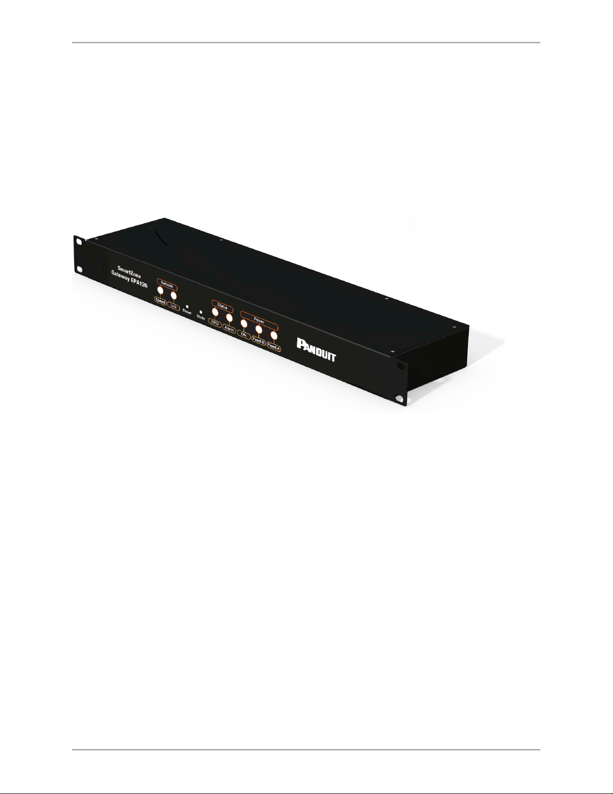
Front of Gateway EPA126
The following image shows the front panel of the EPA126 unit:
LEDs
LEDs can be found on the front of the EPA126 unit. Their purpose is described below.
Network
l Link (green): Embedded in RJ45 Ethernet connection. Illuminates when an Eth-
ernet link is established. Flashes with network activity.
l Speed(amber): Illuminates when 100mbps connection is used.
Status
l CPU: Indicates system activity.
l Alarm: Indicates any alarm condition.
- 9 -
Page 10
SmartZone Gateway EPA126 User Manual
Power
l On: Illuminates when unit is powered.
l Feed B (amber): Illuminates when mains power is present to input Feed B.
l Feed A (amber): Illuminates when mains power is present to input Feed A.
Buttons
There are two buttons on the front of the EPA126 unit:
l Reset: Allows the user to reboot the unit.
l Mode: The mode select switch is used to reset the unit to factory defaults. See the
section for details.
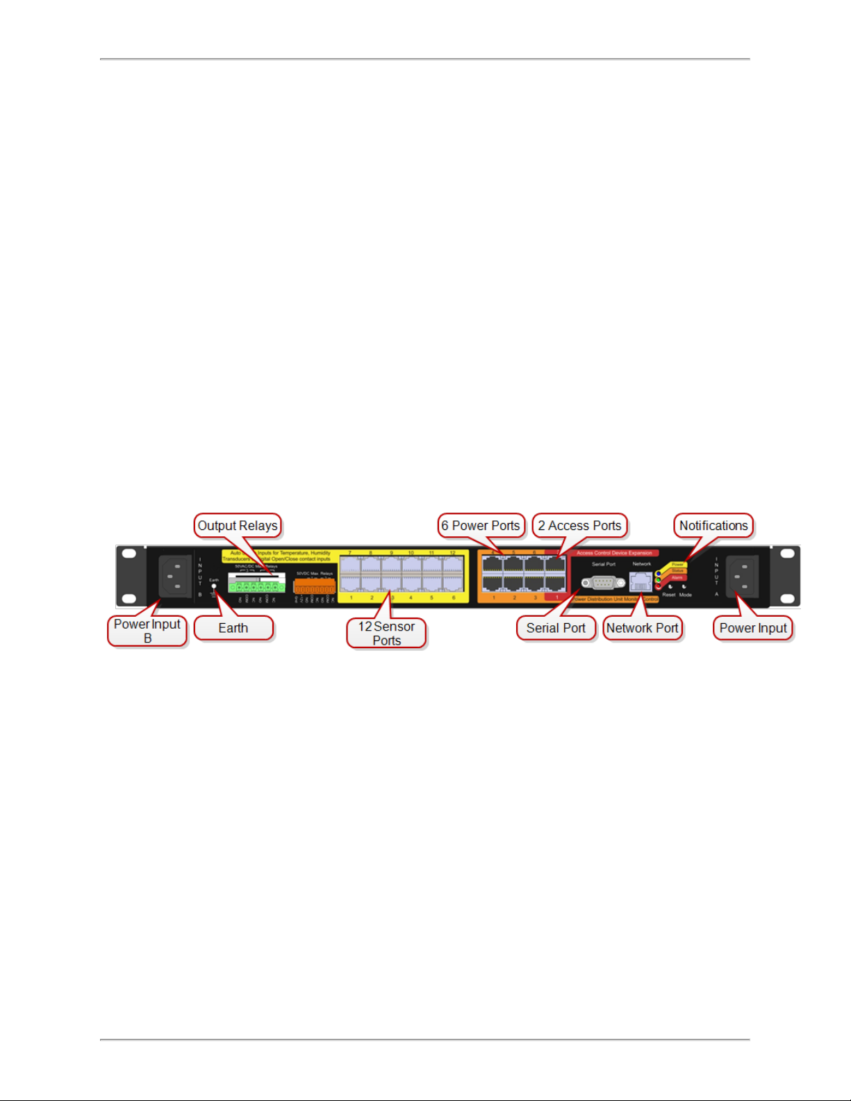
Back of Gateway EPA126
l Power Input B: Redundant mains or -48v DC voltage power feed.
l Earth: Grounding stud.
l Output Relays: Connect up to four output devices (such as Front and Back Elec-
tronic Swing Handles, and more).
l Sensor Ports 1 through 12: Connect up to 12 sensors (such as Temperature,
Humidity, Water, Door Contacts, and more).
l PDU Ports 1 through 6: Connect up to six power devices (such as Gateway-
Enabled Rack PDUs, Inline Meters, and Clamp Meters).
l Access Ports: Connect up to two access and control devices (such as Keypads or
HID Card Readers). Must select one type (not mix and match).
l Serial Port: Attach optional devices (such as LCD Status Monitor Unit).
l Network Port: An RJ-45 port to connect Gateway to LAN/Network.
- 10 -
Page 11
SmartZone Gateway EPA126 User Manual
l Notifications: Reset/Mode/Power/Status/Alarm notifications duplicated from the
Front Panel.
l Power Input A: Mains or -48v DC voltage.
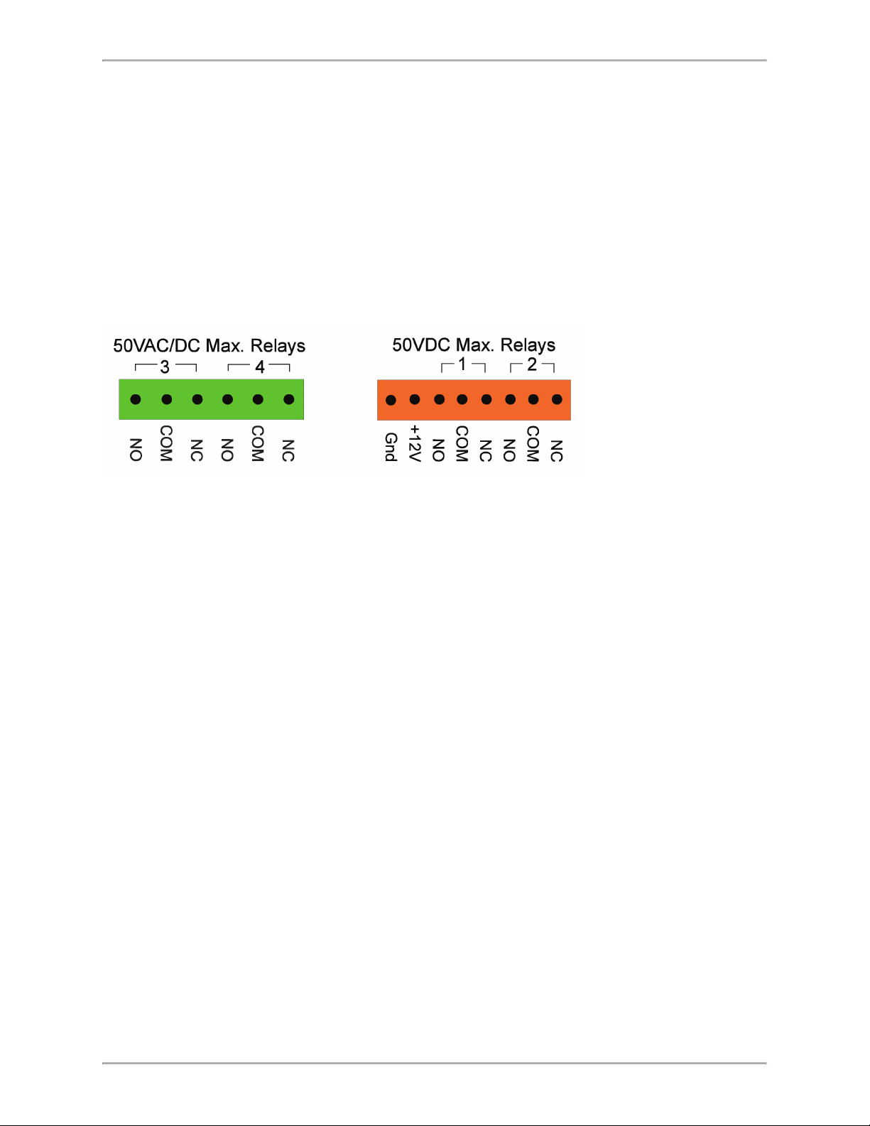
Output Relays
Use the Output Relays to connect up to four output devices (such as Front and Back
Electronic Swing Handles, and more).The following diagram shows the output relays of
the EPA126 unit:
- 11 -
Page 12

SmartZone Gateway EPA126 User Manual
Installation Requirements
l SmartZone Gateway EPA126 unit.
l IEC mains lead (supplied localized).
l Ethernet or Fast Ethernet network connection.
l Network-connected computer system to setup the EPA126 Unit.
Rack Mounting
This section covers the basic 19-inch rack-mounting of the Gateway EPA126 unit.
Equipment Required
You need to supply a number-1 and a number-2 Phillips screwdriver to rack-mount the
Gateway EPA126 unit.
Before You Begin
When determining where to install the Gateway EPA126 unit, please verify that these
guidelines are met:
l Airflow around the Gateway EPA126 is unrestricted.
l Clearance to the front and rear panels meet these conditions:
l Front-panel LEDs can be easily read.
l Access to ports is sufficient for unrestricted cabling.
l AC power cord from the power supply can reach the AC power outlet and the Gate-
way EPA126.
l The 10/100 network cabling does not exceed 100 meters from the Gateway
EPA126 to the Network switch.
l Temperature around the EPA126 does not exceed 40° C.
l Humidity around the Gateway EPA126 does not exceed 90%.
Installation Warning Statements
Note: Only trained and qualified personnel should be allowed to install, replace or ser-
vice this equipment
- 12 -
Page 13
SmartZone Gateway EPA126 User Manual
l To prevent the Gateway unit from overheating, do not operate in an area that
exceeds the maximum recommended ambient temperature of 40° C.
l Installation of the Gateway unit must comply with local and national electrical
codes.
l To prevent personal injury when mounting or servicing the Gateway unit, ensure
that the rack or cabinet is adequately secured so that the system remains stable.
l Circuit Overloading - Consult the equipment nameplate ratings when connecting
the equipment to the supply circuit to avoid overloading of circuits. Overloading circuits can adversely affect current protection and supply wiring.
l Maintain reliable grounding of rack-mounted equipment. Particular attention should
be given to supply connections other than direct connections to the branch circuit
(for example, the use of PDUs).
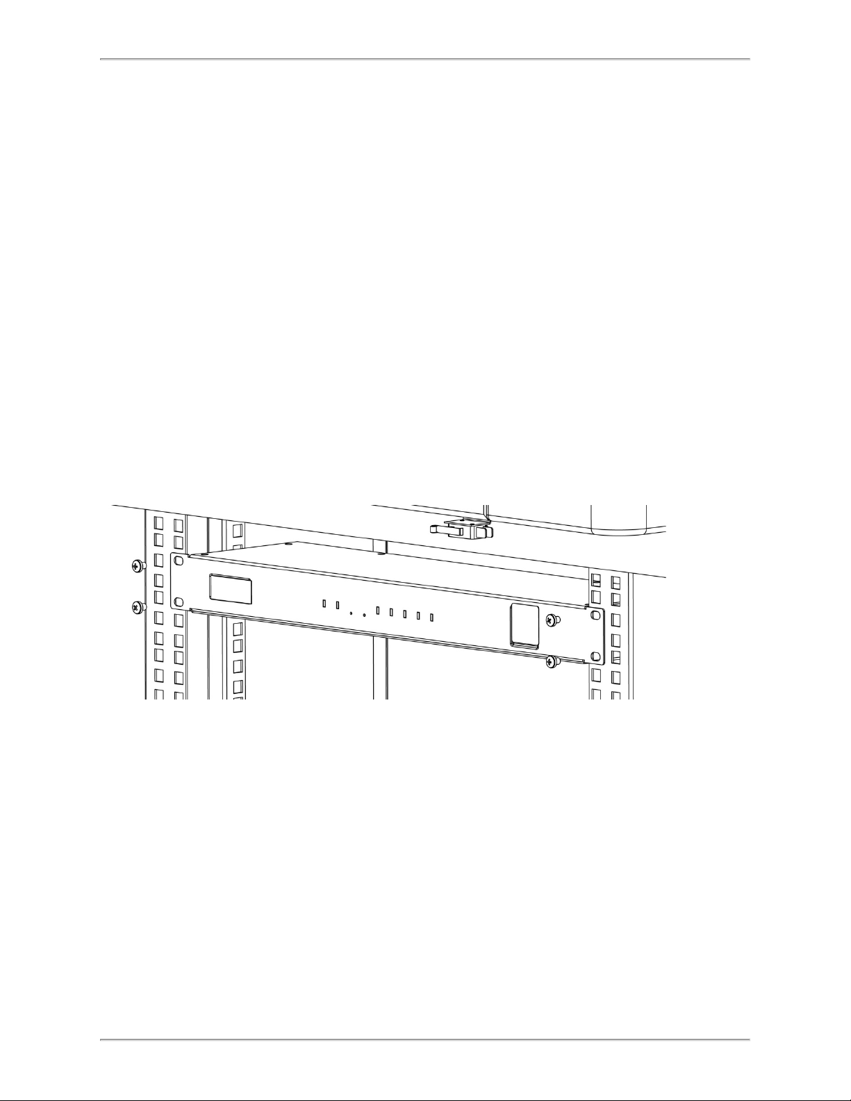
Rack-Mount the EPA126
Hold the Gateway EPA126 and attach the bracket to rack using two 12-24 screws.
- 13 -
Page 14

SmartZone Gateway EPA126 User Manual
Initial Setup
Default Settings
The SmartZone Gateway unit in factory default condition has the following network configuration. Advanced users may wish to make use of these settings to access the Gateway unit's Web Management Interface immediately and proceed with configuration.
Users who do not know how to do this should proceed through this section for information on how to configure the Gateway unit.
IP Address 192.168.0.253
Subnet Mask 255.255.255.0
Default Gateway 192.168.0.1
Web Management Address http://192.168.0.253/
Default username admin
Default password admin
Note: Password entries are case-sensitive.
Connecting to the Web Management Interface
The SmartZone Gateway monitoring solution can be configured entirely using the builtin Web Management Interface.
You may need to change the IP address of the PC to connect to the Web Management
Interface for the first time. The following section details how to change the IP address
and connect to the Web Management Interface.
Changing your PC's IP Address
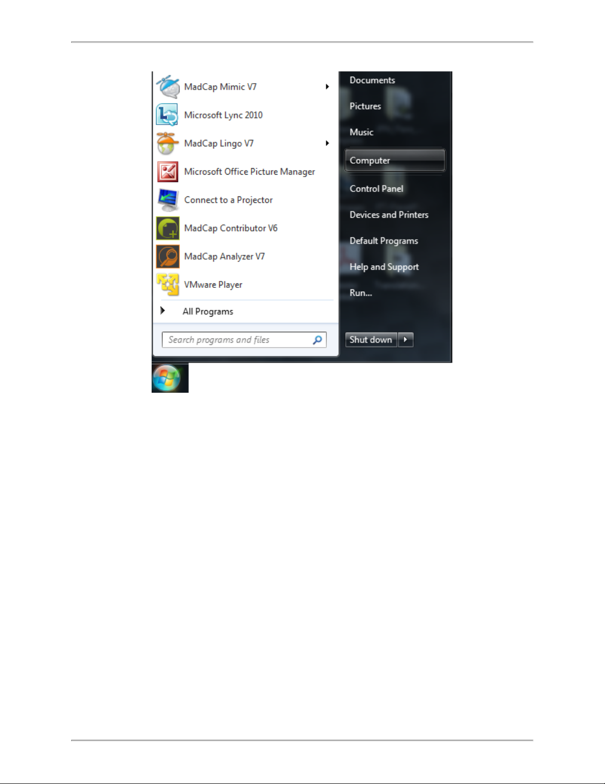
Note: Instructions refer specifically to Windows 7. Please refer to your operating system
documentation if you are not using Windows 7.
1. Click the Windows button and select Control Panel.
- 14 -
Page 15
SmartZone Gateway EPA126 User Manual
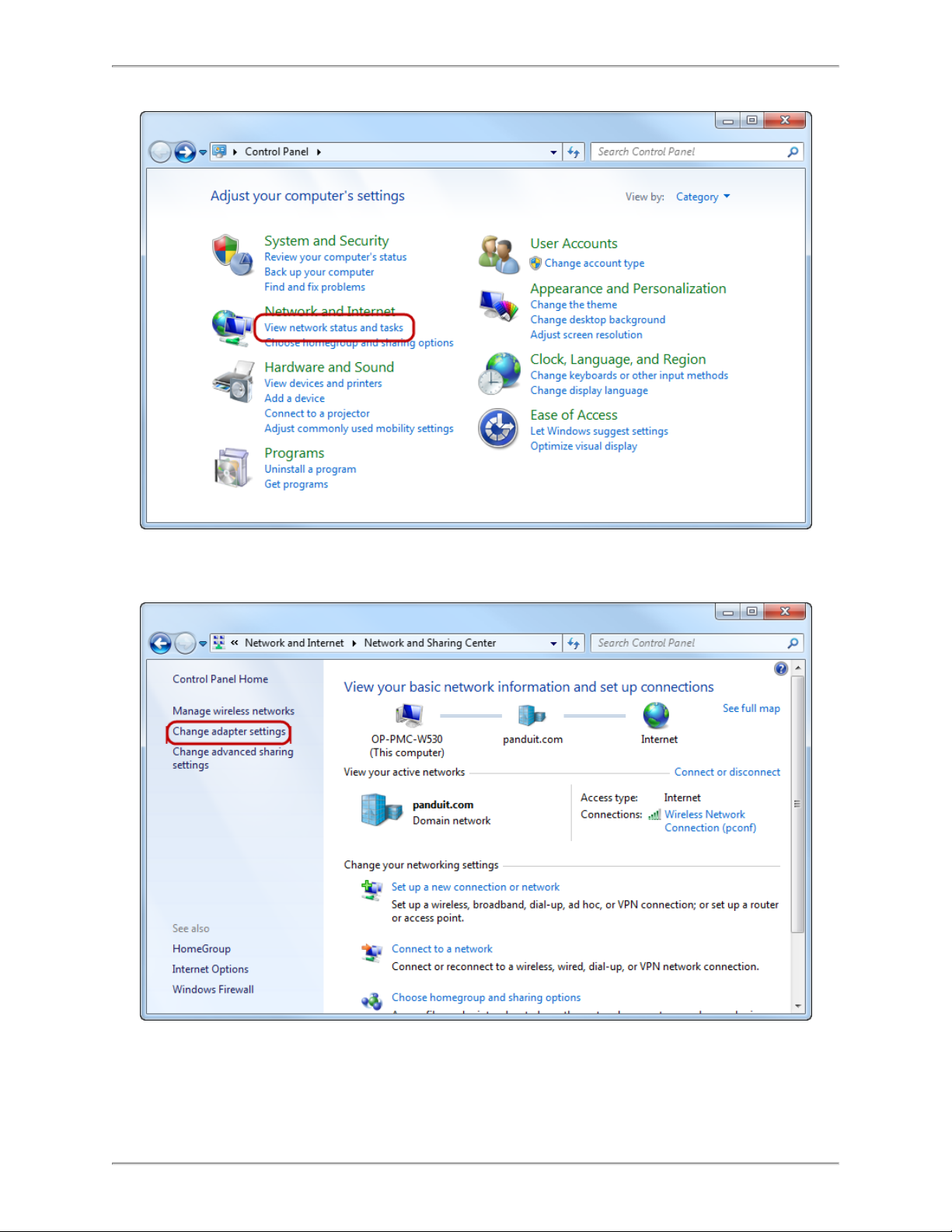
2. In the Control Panel window, select View network status and tasks under the Network and Internet heading.
- 15 -
Page 16
SmartZone Gateway EPA126 User Manual
3. Select Change adapter settings from the menu on the left.
- 16 -
Page 17
SmartZone Gateway EPA126 User Manual
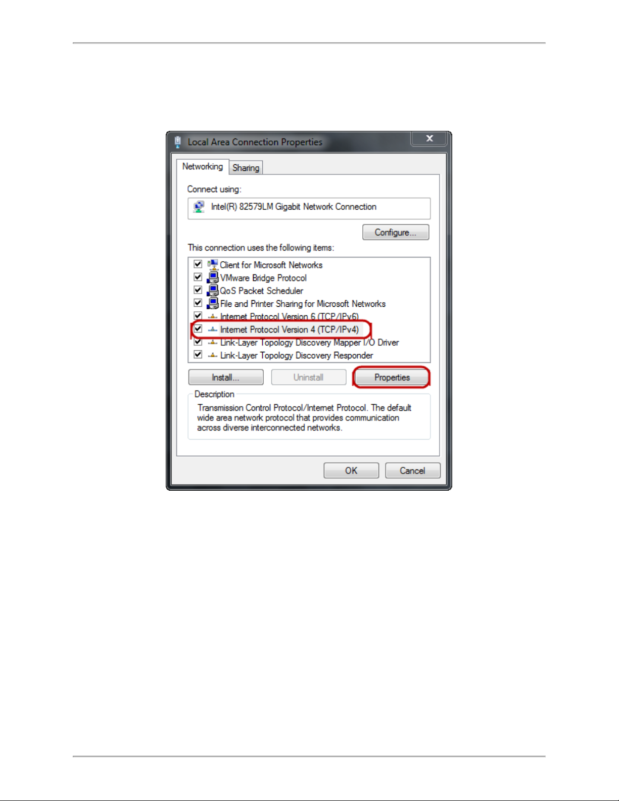
4. Select Local Area Connection.
5. Select Internet Protocol (TCP/IP) Version 4 (you may need to scroll down). Then
click the Properties button.
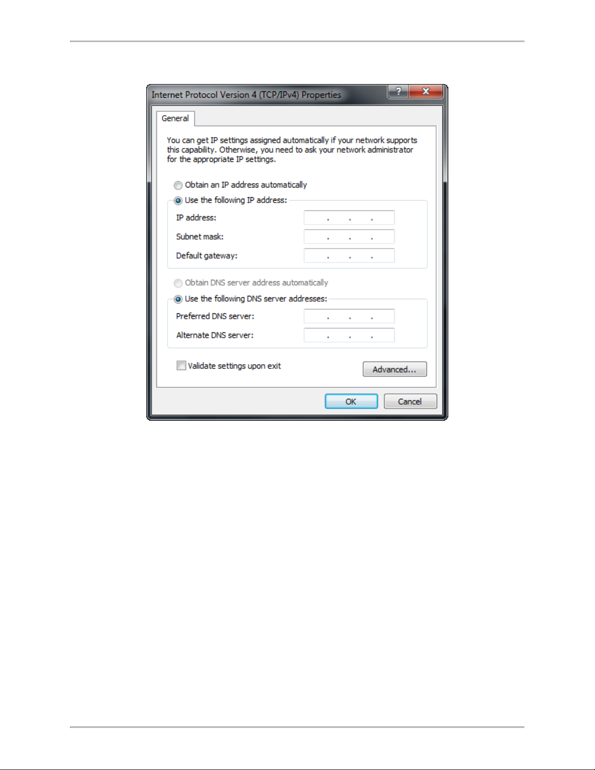
6. Select the Use the following IP address radio button.The Use the following
DNS server addresses radio button then selects automatically.
- 17 -
Page 18
SmartZone Gateway EPA126 User Manual
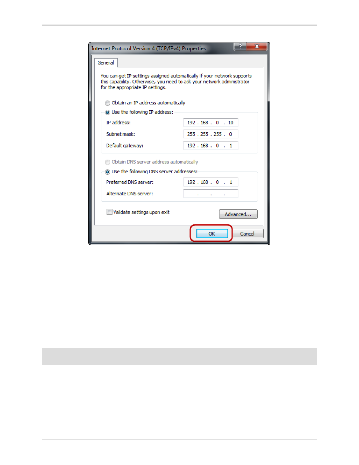
Enter the following details into the appropriate boxes.
l IP address: 192.168.0.10
l Subnet mask: 255.255.255.0
l Default Gateway: 192.168.0.1
l Preferred DNS server: 192.168.0.1
7. Click OK to accept the entries.
- 18 -
Page 19
SmartZone Gateway EPA126 User Manual
8. On the Local Area Connection Properties, click OK to return to the desktop.
Connecting to the SmartZone Gateway Web Management Interface
1. Connect the SmartZone Gateway unit's network connection directly to a PC's Ethernet network card using a patch cable.
Note: A crossover cable must be used when directly connecting the Gateway unitto a
PC's network card.
2. Power the Gateway unit.
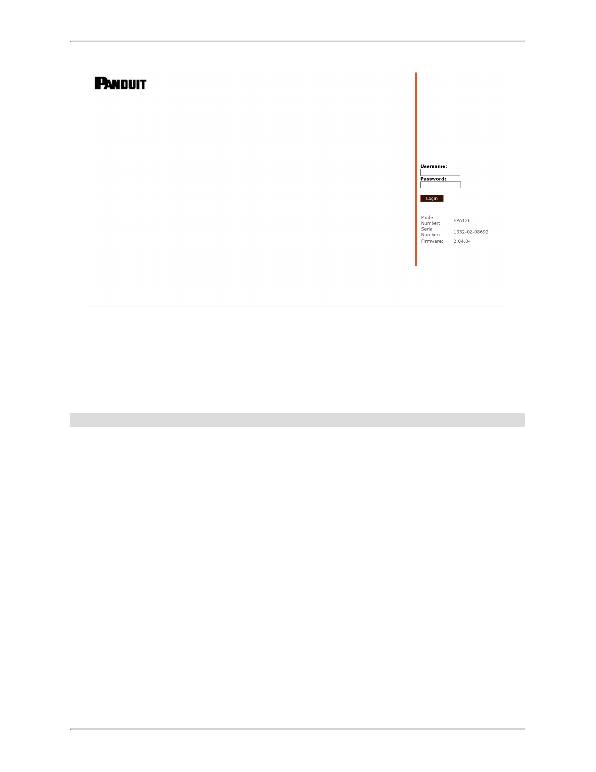
3. Open a web browser.
4. Enter the following in the address field: http://192.168.0.253.
5. The Web Management Interface loads.
- 19 -
Page 20
SmartZone Gateway EPA126 User Manual
6. Click login and enter the username and password. The unit defaults are:
l Login: admin
l Password: admin
Note: Password entries are case sensitive.
- 20 -
Page 21
SmartZone Gateway EPA126 User Manual
Initial Network Setup
This section provides details on preparing the unit for network access and allowing
Simple Network Management Protocol (SNMP) network management.
Connection to the Web Management Interface is required.
Entering NMS Details
1. Click the Setup tab on the top menu bar, and then select the SNMP NMS link on
the left menu bar.
2. If you select SNMPv2, select the version of SNMP agent to be supported. Then set
the SNMPv2 parameters (your chosen community string) and required Network
Management Station (NMS) access permissions of the NMSs to be used.
3. Click Save to confirm the changes.
4. If you select SNMPv3, then you will need to enter additional parameters.
- 21 -
Page 22
SmartZone Gateway EPA126 User Manual
5. Security mode:
l AuthNoPriv – In this mode, access is granted only if the NMS is authorized (has a
User Name and knows the password). The transfer of data between the gateway
and the NMS is not encrypted in this mode.
l AuthPriv - In this mode, access is granted only if the NMS is authorized (has a user
name and knows the password). The data transferred between the gateway and
the NMS is encrypted. The encryption uses a shared secret “Privacy Password”
which must be set in both the gateway and the NMS.
6. USM Access privilege:
l Read Only - In this mode, the NMS user will have read-only access to the SNMP
MIB data objects.
l Read / Write - In ths mode, the NMS user will have read and write access to the
SNMP MIB data objects.
7. User Name:
l Enter a user name to be associated with the Security/USM access model that has
been defined for this user.
8. Authentication Password
- 22 -
Page 23
SmartZone Gateway EPA126 User Manual
l Enter an authentication password for the user.
9. Privacy Password
l Enter a pass phrase to be shared with the NMS. This pass phrase is used to gen-
erate the encryption/decryption keys used for encrypting the SNMP data between
the gateway and NMS.
Entering Trap Receiver Details
1. Click the Setup tab on the top menu bar.
2. Select the SNMP Rec’rs link on the left menu bar.
3. Enter the IP address.
4. Select the required trap version to v2 traps for v2.04.04 firmware.
l v1 SNMP Traps currently NOT supported.
l v2 SNMP Traps is the RECOMMENDED setting.
l v3 Notifications do not support encryption or authentication.
- 23 -
Page 24
SmartZone Gateway EPA126 User Manual
5. Choose whether to enable traps, disable traps, or enable traps including authorization failures (meaning the unit will issue traps if an unauthorized IP address
attempts to access the unit's SNMP functions) for each receiver.
6. Click Save to confirm the changes.
Adding Users
1. Click the Setup tab on the top menu bar.
2. Select the Userslink on the left menu bar.
3. You can set usernames, passwords, and access levels here. Unique usernames
can be set for individuals who require web management access to the Gateway
unit.
4. Click Save to confirm the changes.
Changing the Unit IP Address
1. Click the Setup tab on the top menu bar.
2. Select the IP Config link on the left menu bar.
- 24 -
Page 25
SmartZone Gateway EPA126 User Manual
3. Set the IP Stack Selection to Dual – this is the only mode currently supported.
Note: Selecting either of the other options is not supported.
4. Enter the IP Address, Subnet Mask, and the Gateway address that the SmartZone
Gateway unit will use (required). Contact your network administrator if you do not
know the values that you must enter here.
5. Select the Config. Protocol (Static or DHCP).
6. Enter the SNMP System Name, System Location , and Contact Name if required.
These fields will be added to all SNMP traps generated by the unit.
7. Click Save to confirm the changes.
8. To prevent the firmware from being updated using the insecure TFTP, configure
Upgrade Port (69) to Disabled.
9. Click Restart ,and then select Restart Now to reboot the unit and implement the
changes.
Note: Once the IP configuration has changed, the Gateway unit will no longer be accessible via the default IP address, because the new address will be operational.
The Gateway unit should now be connected to the main network and any further
required configuration will be done via the unit's new IP address.
- 25 -
Page 26
SmartZone Gateway EPA126 User Manual
HID Reader
The SmartZone EPA Series Gateways include Smart Card readers that support HID 26
bit cards and HID Corporate 1000 cards.
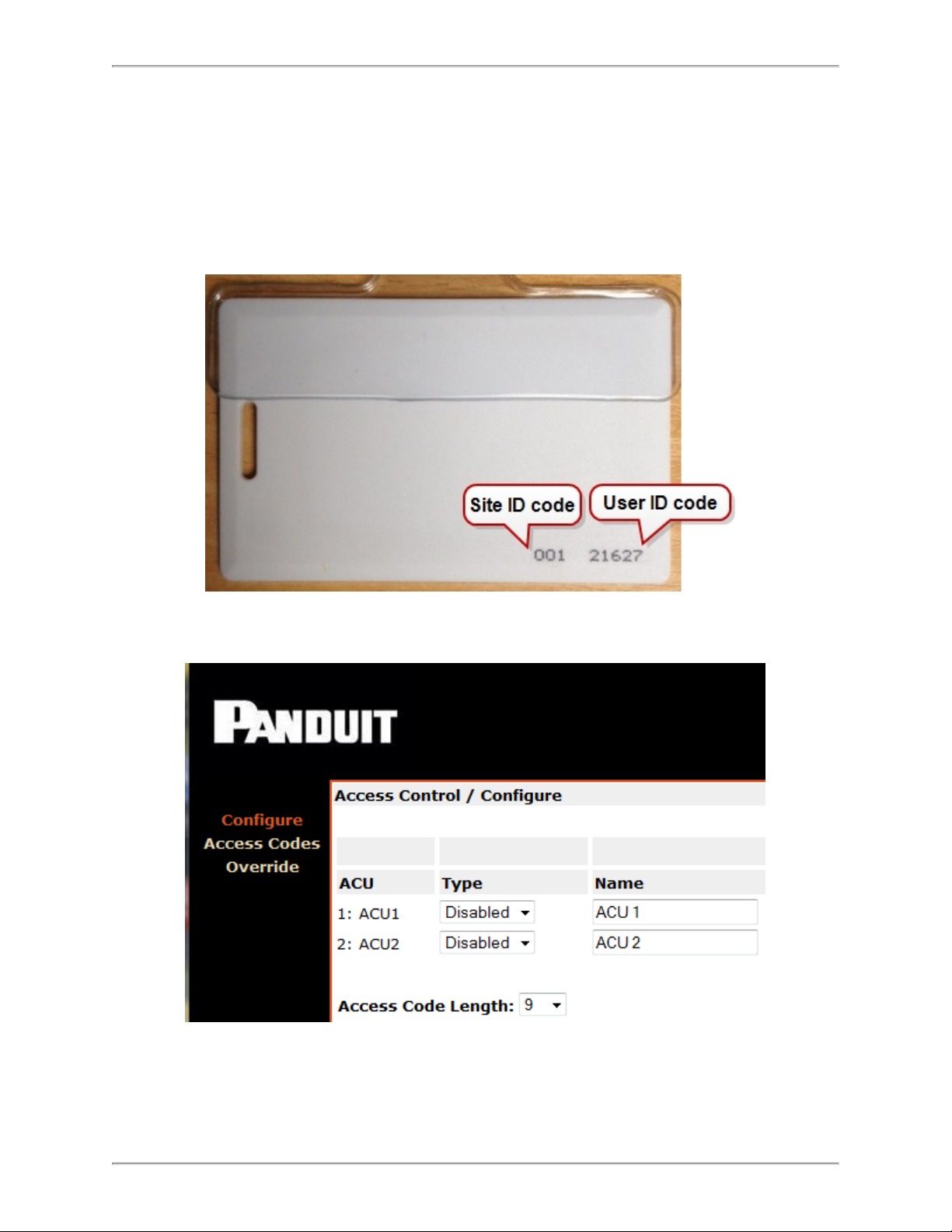
HID 26 Bit Cards
For 26 Bit cards the Gateway interface must be programmed for nine digits.
These nine digits consist of the following:
- 26 -
Page 27
SmartZone Gateway EPA126 User Manual
l 3-digit site code
l 1 hyphen
l 5-digit User ID code
Example: 001-21627
Note: The hyphen character must be input (it is included in the length).
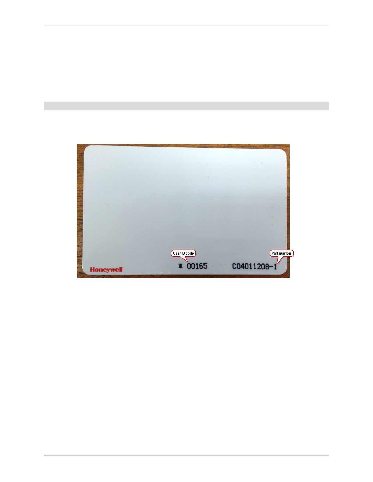
HID Corporate 1000 Cards
Corporate Site IDs are not normally printed on HID Corporate 1000 cards. This is confidential to each organization. You will need to ask the security office of the organization
or supply company for the Site ID code, which is a four-digit number.
For 34 Bit Corporate 1000 cards, the Gateway interface must be programmed for 12
digits.
- 27 -
Page 28

SmartZone Gateway EPA126 User Manual
These 12 digits consist of the following:
l 4-digit site code
l 1 hyphen
l 7-digit User ID code
Example: 0001-2162731
Note: The hyphen character must be input (it is included in the length).
If the user ID code does not have seven digits, then the ID number must be padded out
with leading zeros. Thus an ID code of “00165” becomes: “0000165”.
Example for a card with a 2033 Site ID: 2033-0000165
- 28 -
Page 29
SmartZone Gateway EPA126 User Manual
Web Management Interface
The SmartZone Gateway unit has a built-in Web Management Interface that can be
accessed securely. The interface permits complete configuration and monitoring of the
Gateway unit.
Windows where changes can be made have a Save button in the lower right-hand area.
Click Save to activate and save any changes made.
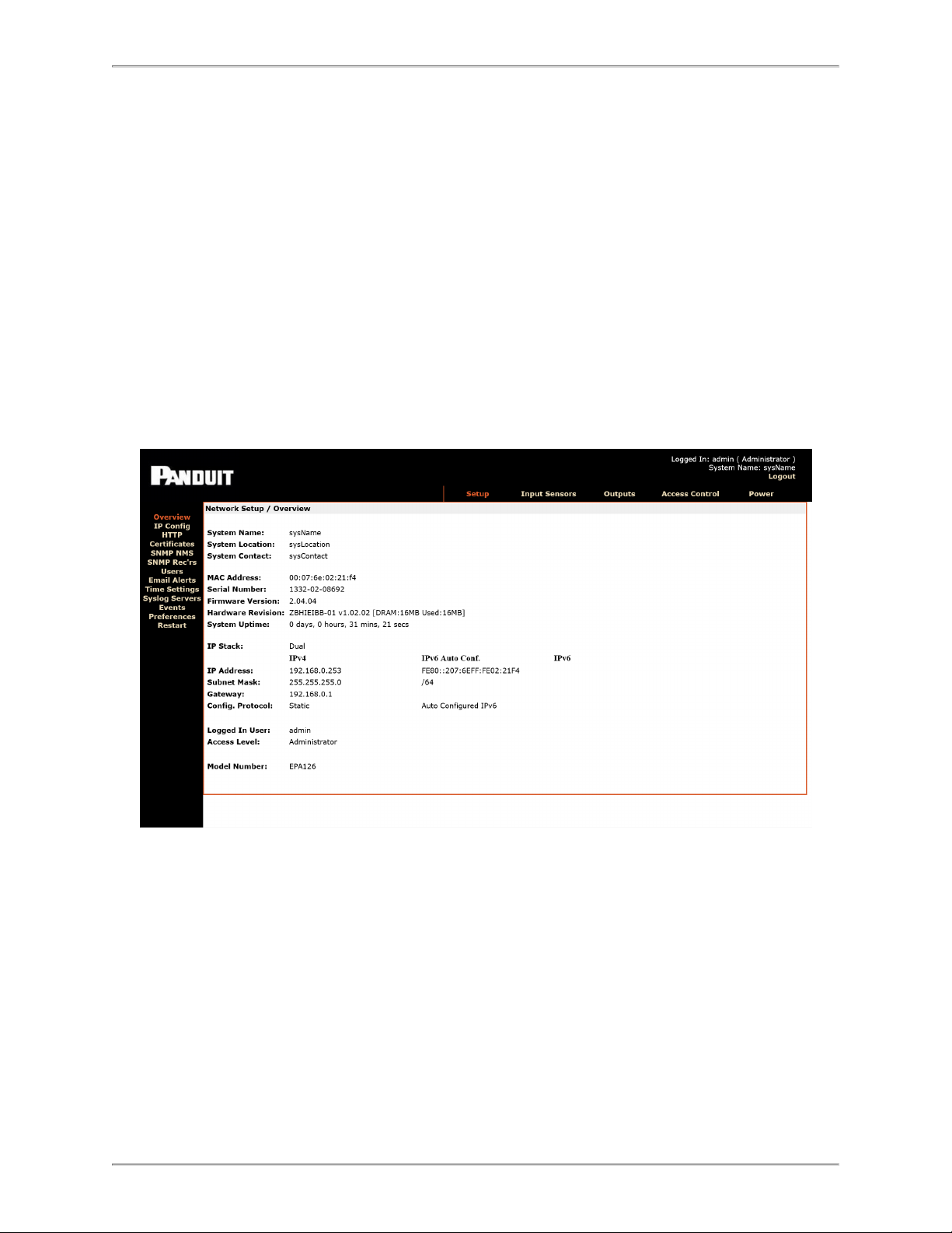
Network Setup - Overview
The Overview page is the first page displayed and provides the user with an overview of
the Gateway unit’s current status.
System name, MAC address, serial number, firmware version, and other system details
can be found here.
- 29 -
Page 30

SmartZone Gateway EPA126 User Manual
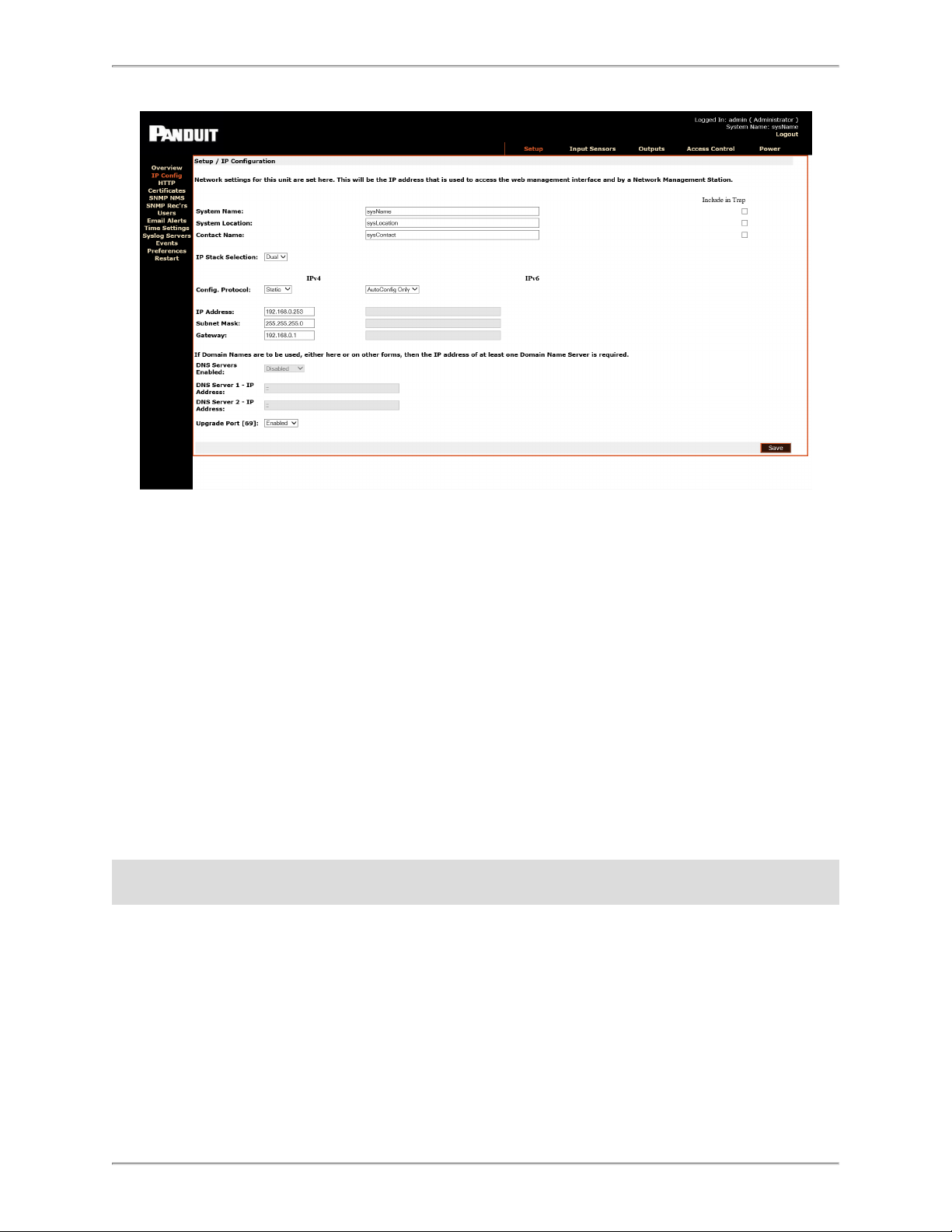
Setup - IP Configuration
The IP Config page allows you to set the SmartZone Gateway unit's own management
IP address.
System Name
You can specify the system name here. This is normally the Fully Qualified Domain
Name (FQDN) of the device, but this is not enforced.
You can retrieve the value specified here by querying the sysName node via SNMP.
This allows SNMP management platforms to obtain unique names for units where specified. This value has no effect on network communications, and the unit will function correctly with or without a value.
System Location
You can specify the system location here.
You can retrieve the value specified here by querying the ‘sysLocation’ node via SNMP.
This allows SNMP management platforms to obtain location names for units where specified. This value has no effect on network communications, and the unit will function correctly with or without a value.
- 30 -
Page 31

SmartZone Gateway EPA126 User Manual
Contact Name
You can retrieve the unit support contact name by querying the ‘sysContact’ node via
SNMP. This value has no effect on network communications and the unit will function
correctly with or without a value.
IP Address
You can enter a standard IP address here. The address is entered in decimal format (for
example: 192.168.0.44 or 22.10.45.33). The address entered here will be the address by
which the Gateway unit is accessed and managed.
Subnet Mask
The subnet mask is used to determine what part of the IP address is the network portion
and what part is the host portion.
It is often 255.255.0.0 or 255.255.255.0. The correct setting is essential for correct operation.
The subnet mask is entered in decimal format (for example: 255.255.255.0 or
255.255.224.0).
Gateway
The Gateway setting specifies the IP address of the machine/router that the Gateway
unit uses to communicate with different networks.
The Gateway address is entered in decimal format (for example: 192.168.0.1 or
11.2.24.103).
Most networks will have a Gateway. Correct setting is important for correct network communications.
Config. Protocol
Select the configuration protocol. Choices include:
l Static
l DHCP
- 31 -
Page 32

SmartZone Gateway EPA126 User Manual
Upgrade Port
Upgrade Port provides a method for upgrading the Gateway firmware when a new version becomes available. Because this uses the TFTP protocol, users may wish to disable the port to prevent unauthorized updates.
Note: Once you enter the IP Configuration options and click Save, the changes take
effect. If incorrect entries are made, this may result in loss of communication. If this happens, reset the Gateway unit's network configuration. Details of how to do this can be
found in the Troubleshooting section.
Setup - HTTP
Select the access method for the Web Management Interface here. Both HTTP and
HTTPS access modes are available by default. Selecting the HTTPS Only radio button
will allow only HTTPS configuration.
Use of HTTPS is recommended for security, because the connections will be encrypted.
Additionally, you can specify the TCP port for connection to the Web Management Interface here. If you have specific requirements for default ports, these can be left at their
default settings (for example, port 80 for HTTP and port 443 for HTTPS).
Note: Changing the selection to HTTP or HTTPS requires a reboot for the selection to
take effect.
- 32 -
Page 33

Setup - Certificates
SmartZone Gateway EPA126 User Manual
This web page will enable users to upload their own certificates (self-signed or CA certificates). The file names restrictions are listed on the web page.
The file naming restrictions are:
1. The certificate filename must be: "ServerCertificate.pem"
2. The key filename must be: "ServerKey.pem" Note: RSA key length must be 2048.
3. The CA certificate filename must be: "CA.pem"
Application requires following CA (Certificate Authority) issued certificates:
1. CA.pem - CA certificate required for client certificate verification.
2. ServerCertificate.pem - CA signed server certificate with public key. This certificate
will be sent to client during authentication.
3. ServerKey.pem - Server's RSA encrypted private key, required to decrypt client's
random key.
The CA certificates can be issued by a public or private Certificates Authority. The client
browser must be configured to connect to the CA server to validate the certificate.
- 33 -
Page 34

SmartZone Gateway EPA126 User Manual
When uploading CA certificates, you must upload three files:
When uploading self-signed certificates, CA.pem is not required:
- 34 -
Page 35

SmartZone Gateway EPA126 User Manual
When using a self-signed certificate, the connection will be encrypted but a warning message will pop-up notifying the user that the certificate cannot be trusted.
After uploading the certificates, the gateway will validate them and it will display the
either success message:
Or the failure message:
- 35 -
Page 36

SmartZone Gateway EPA126 User Manual
After successfully uploading the certificates, restart the gateway to restart the web server
using the new uploaded certificates. When contacting the device in secure mode, the
user must make sure to add ‘https://’ in front of the IP address:
These are the commands to generate a self-signed certificate:
openssl genrsa -out ServerKey.pem 2048
openssl req -new -sha256 -key ServerKey.pem -out csr.csr -subj
"/C=UK/ST=Wales/L=Usk/O=Panduit/CN=192.168.0.253"
openssl req -x509 -sha256 -days 7300 -key ServerKey.pem -in
csr.csr -out ServerCertificate.pem
openssl req -in csr.csr -text -noout | grep -i "Signature.*SHA256" && echo "All is well" || echo "This
certificate will stop working in 2037!”
- 36 -
Page 37

SmartZone Gateway EPA126 User Manual
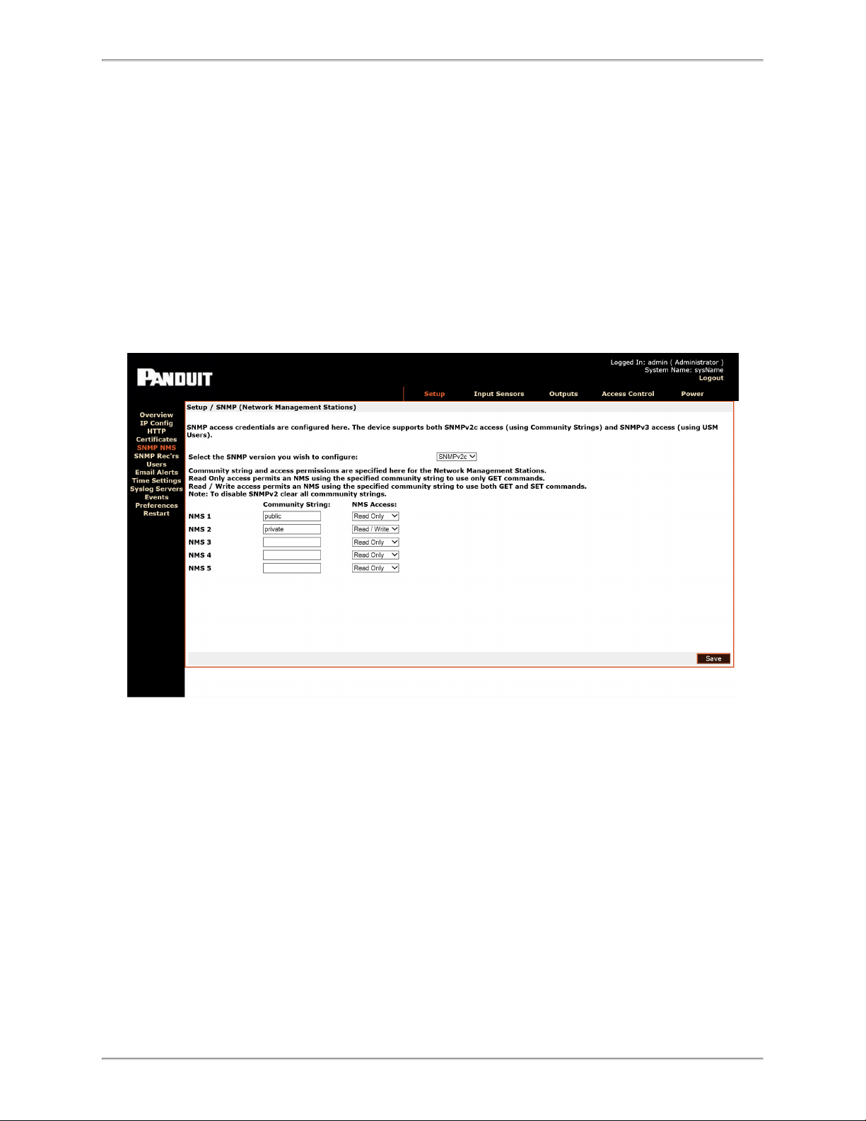
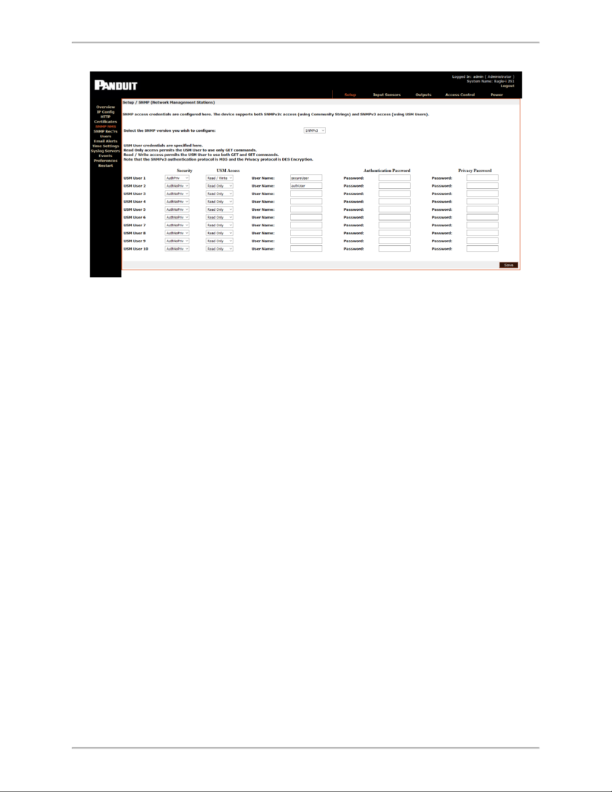
Setup - SNMP NMS
Specify the SNMP version, community string, and access permissions for up to five Network Management Stations here.
Any machine that needs to access the unit’s SNMP functions must be entered here.
SNMP Version
Enter the SNMP version of the NMS machine here. If you select SNMP v3, follow the
instructions in SNMP v3
Community String
You must enter the required community string here. The default for many devices is public. It is recommended that the community string be changed, because it serves as an
access password.
NMS Access
Read-only access permits the NMS to use only GET commands. Read/Write access permits the NMS to use both GET and SET commands.
- 37 -
Page 38

SmartZone Gateway EPA126 User Manual
SNMP v3
If you select SNMPv3, then additional parameters must be entered.
Security Mode
l AuthNoPriv – In this mode, access is granted only if the NMS is authorized (has a
User Name and knows the password). The transfer of data between the gateway
and the NMS is not encrypted in this mode.
l AuthPriv - In this mode, access is granted only if the NMS is authorized (has a
user name and knows the password). The data transfers between the gateway and
the NMS are encrypted. The encryption will use a shared secret “Privacy Password” which must be set in both the gateway and the NMS.
USM Access Privilege
l Read Only - In this mode, the NMS user will have read only access to the SNMP
MIB data objects.
l Read/Write - In this mode, the NMS user will have read and write access to the
SNMP MIB data objects.
- 38 -
Page 39

SmartZone Gateway EPA126 User Manual
User Name
l Enter a user name to be associated with the Security/USM access model that has
been defined for the user.
Authentication Password
l Enter an authentication password for the user.
Privacy Password
l Enter a pass phrase that will be shared with the NMS. This pass phrase is used to
generate the encryption/decryption keys used for encrypting the SNMP data
between the gateway and NMS.
- 39 -
Page 40

SmartZone Gateway EPA126 User Manual
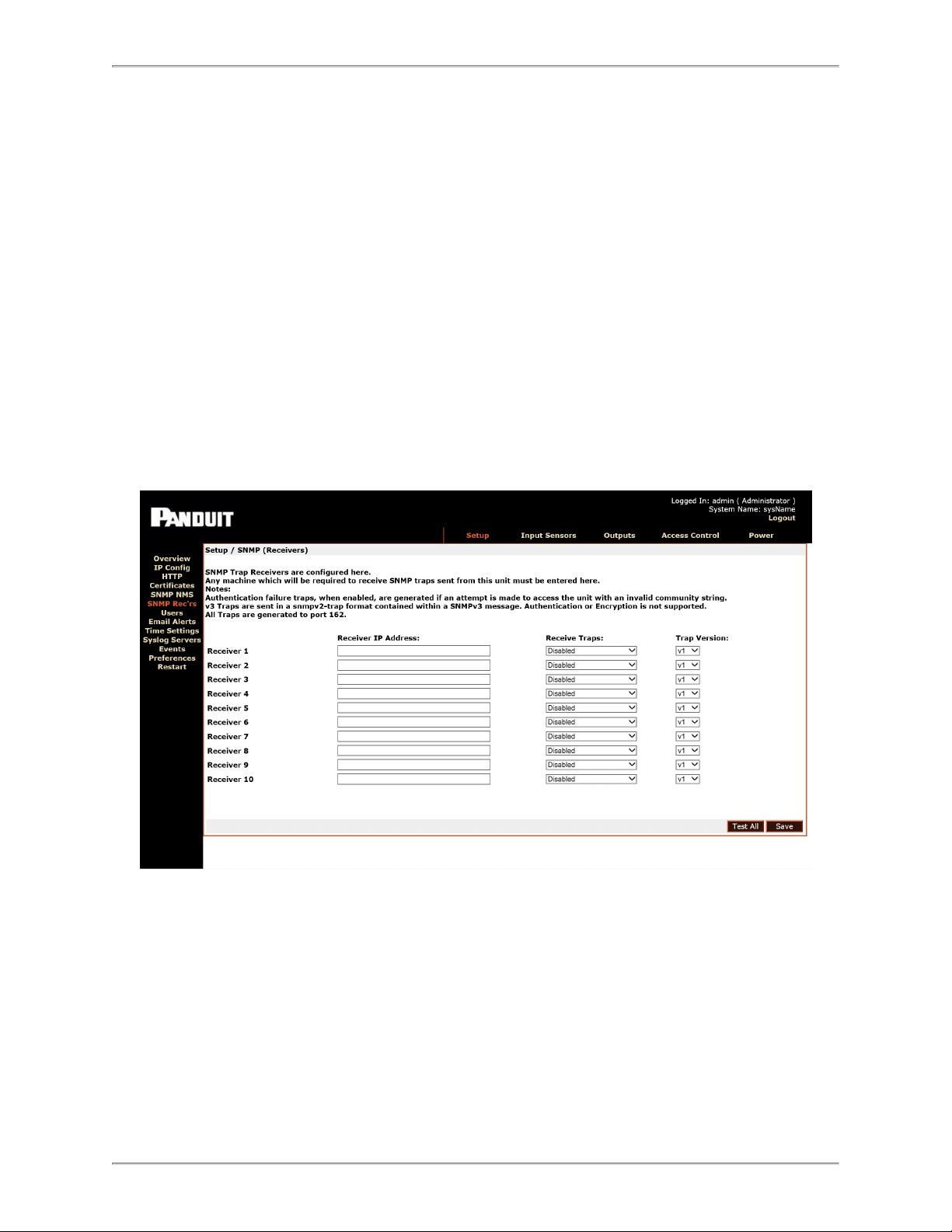
Setup - SNMP Receivers
Specify the IP address, community string, and access permissions for up to 10 Network
Management Stations here.
Receiver IP Address
You must enter any machine that is required to receive SNMP traps sent from this unit.
Usually any SNMP NMS entries should also be entered.
Trap Version
The required trap version must be selected here.
Select the required trap version to v2 traps for v2.04.04 firmware.
Notes:
l v1 SNMP Traps currently NOT supported.
l v2 SNMP Traps is the RECOMMENDED setting.
l v3 Notifications do not support encryption or authentication
- 40 -
Page 41

SmartZone Gateway EPA126 User Manual
Receive Traps
The Receive Traps Enabled setting allows the specified NMS to receive the unit's standard range of traps. Receive Traps Enabled (incl Auth fails) will cause the unit to issue
traps if an unauthorized IP address attempts to access the unit's SNMP functions.
Receive Traps Disabled prevents traps from being sent to the specified NMS IP
address.
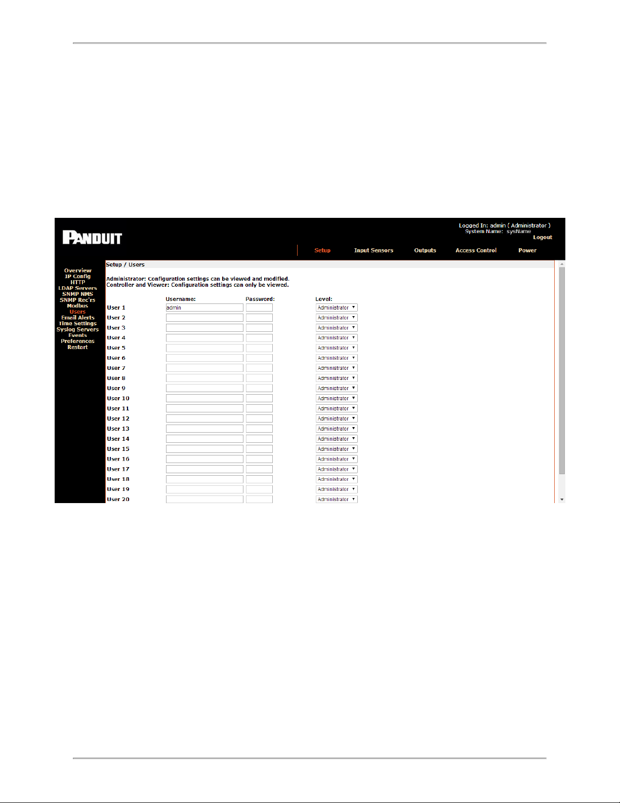
Setup - Users
You can add users with permission to access the Web Management Interface here.
Access passwords are also specified along with users' access permissions.
Username
Enter the required username. This is the username that will be required to login to the
Web Management Interface.
Password
Enter access passwords on a per-user basis.
- 41 -
Page 42

SmartZone Gateway EPA126 User Manual
Level
Three user levels are available for assignment.
l Administrator : Administrators have full control of SmartZone Gateway con-
figuration settings.
l Controller : Controllers can view configuration settings.
l Viewer : Viewers can view configuration settings.
Warning: User 1 / admin is the master administrator. It is possible to remove administrator rights from the admin user. Doing this is not recommended as it may result in no
one having administrator access. In this situation, a reset to factory defaults is the only
solution. Details on how to do this can be found in the Troubleshooting section.
Setup - Email Alerts
On this page, you can edit email alert settings for traps. You may set up to 10 email
receivers.
Email Alerts
SMTP Relay Server The IP Address of the SMTP Server
From Address Address from which the alert emails are sent
- 42 -
Page 43

SmartZone Gateway EPA126 User Manual
Email Alerts
Reply-To Address Address to which the email receivers can reply
Destination Address Address that will receive the email alerts
Enabled Toggle the check box to enable or disable alerts to each address
Repeat Timer Number of minutes after which the email alert will repeat
Setup - Events
The Events page shows a history of events that have occurred, along with specific
details about each event.
To specify a range of events to view, select the desired year and month from the dropdown menus, then click Show.
Date/Time, Type, User, and Event Data for each event are displayed.
Events can be ordered Latest First or Earliest First by clicking the corresponding radio
button.
Setup - Syslog Servers
This page allows you to view or edit information about the Syslog Servers currently
being used.
- 43 -
Page 44

SmartZone Gateway EPA126 User Manual
From the Enabled drop-down menu, you can choose which syslog servers are enabled.
Fill in the following fields for each Syslog server.
Syslog Server Setup
Display Name The name of the Syslog server
IP Address The IP address of the Syslog server
Port The number of the port being used
Log Event Types Click the check boxes to choose which events to log
Setup - Time Settings
The Time Settings page allows you to view or edit the current date and time.
- 44 -
Page 45

SmartZone Gateway EPA126 User Manual
Select the correct day, month, and year from the dropdown menus, and verify the local
time. If you want to change the time, you must check the Update time checkbox.
Time Adjustments
Select the correct time zone from the drop-down menu.
l Daylight Saving can be enabled or disabled by clicking the check box. If Daylight
Saving is enabled, select start/stop dates from the subsequent drop-down menus.
l Date Format allows the administrator to choose whether the date is displayed with
the day or month first. For example, the date August 20, 2013 can be displayed in
one of two ways:
20/08/2013 (DD / MM / YYYY)
or
08/20/2013 (MM / DD / YYYY)
Select the desired format from the dropdown menu.
l SNTP Servers - Simple Network Time Protocol synchronizes the clocks of com-
puter systems over a network. Enter the IP address of an SNTP server, and specify
(in hours) how often the time should be updated.
- 45 -
Page 46

SmartZone Gateway EPA126 User Manual
Setup - Preferences
The Preferences page allows you to edit system preferences.
Preferences
From the dropdown menu, select the first page you want to open
Default Page
when a user logs in. The preset default page is the Overview
page.
Choose from the dropdown menu where the timestamp will be
found on traps. There are three options:
Time stamp Traps
l Prefix – timestamp at the beginning
l Append – timestamp at the end
l None – no timestamp
User Session
Timeout
Enter a number of minutes, after which a session will be timed
out if the user is inactive.
Temperature Scale Select Celsius, Fahrenheit, or Kelvin from the drop-down menu.
Page Refresh Period
Enter a number of seconds, after which the page will automatically refresh. If 0 is entered, the page will not refresh automatically.
- 46 -
Page 47

SmartZone Gateway EPA126 User Manual
Preferences
Browser Auto-
complete
If this feature is Enabled, the browser assists with text field entry
by presenting previously used values for user selection. If Dis-
abled, no such values are presented.
Setup – Restart
A unit may be rebooted or reset to factory defaults here.
Restart Unit
Restart Now
Selecting Restart Now commands the unit to reboot. Rebooting the unit will cause any
outstanding configuration changes to take effect.
Reset to Factory Defaults
See Troubleshooting for instructions on resetting the factory default settings for the unit.
- 47 -
Page 48

SmartZone Gateway EPA126 User Manual
Input Sensors – Configuration and Status
Status
The Input Sensors status page presents an overview of the input ports. This page displays the input channel number, name, type of input sensor, status, current readings, and
thresholds.
Status Indicators
Three status indicators are displayed next to input channels to allow quick determination
of normal, warning, and critical alarm statuses:
Channel reading currently within threshold limits.
Upper or lower Warning limit reached or exceeded.
Upper or lower Critical limit reached or exceeded.
- 48 -
Page 49

SmartZone Gateway EPA126 User Manual
Input Sensors – Defaults
The Input Sensor Defaults menu allows configuration parameters for input sensors of
specific types to be defined and applied to all inputs of that type.
The types of input sensors are:
l Temperature
l Humidity
l Analog (Voltage)
l Open/Close Contacts (digital inputs)
The configurable defaults are described below.
Calibration Offset
The value entered here alters the actual reading of a sensor by the amount specified.
For example, if a Calibration offset of 6 was used and a sensor's true reading was 36,
the indicated reading used for display and alarm purposes would be 42. This works the
same way for both temperature and humidity sensors.
Hysteresis Value
The hysteresis default value to be applied to sensors is specified here. The value specified is an offset from a sensor's threshold values.
For example, a hysteresis value of 5 would mean that, in the case of an Upper Control
Limits alarm, the alarm value would have to reduce to 5 below the threshold value before
another alarm is issued.
Please see Appendix B: Hysteresis Demystified for detailed information.
Limits and Traps
You can set default values for sensor alarm thresholds here. You also can set the default
settings for alarm threshold traps here.
The following thresholds can be set:
- 49 -
Page 50

SmartZone Gateway EPA126 User Manual
l Upper Control Limit
l Upper Warning Limit
l Lower Control Limit
l Lower Warning Limit
You can apply default trap settings for all of these thresholds. With the trap box deselected, no SNMP alarm traps will be generated, even when an alarm condition exists for
that threshold.
Repeat Timer
The repeat timer causes alarm traps to be reissued after a specified amount of time if the
alarm condition persists.
Setting the repeat timer to zero will disable the repeat traps.
The defaults that can be set for Open/Close contacts differ from the Temperature and
Humidity settings.
Normal State
Normal state specifies the condition in which a contact is considered to be in a Normal,
Non-alarmed state.
Devices such as smoke alarms and air conditioning units often have normally open contacts. To receive alarm indications from these types of units would cause alarms to be
issued when a monitored contact closes.
Setting normally closed in the case of a rack or cabinet door would cause an alarm condition when the door was opened.
Trigger Type
The trigger type defaults for Open/Close sensors are specified here.
The three available options for trigger types are:
Level
Level triggering is the default mode. When an input physically transitions from a Normal
to Non-Normal state, an alarm is triggered. However, the alarm persists only while the
- 50 -
Page 51

SmartZone Gateway EPA126 User Manual
input remains in a Non-Normal state. When the input returns to a normal state, the alarm
is cleared.
Normal to Non-Normal (Positive Edge)
This type of triggering may be used in situations where a momentary type input (for
example, a shock sensor or PIR) is used. Since these types of inputs are momentary,
any alarm condition that occurs will persist until manually cleared.
Positive Edge triggering is used when an alarm is required to persist after an input
changes from the Normal state to the Non-Normal state.
Non-Normal to Normal (Negative Edge)
This type of triggering may be used in situations where a momentary type input (for
example, a shock sensor or PIR) is used. Since these types of inputs are momentary,
any alarm condition that occurs will persist until manually cleared.
Negative Edge triggering is used when an alarm is required to persist after an input
changes from the Non-Normal to the Normal state.
Input Sensors - Configure
You can configure the individual sensor channels in this window.
Select the Config option to open a detailed configuration page for the selected sensor.
- 51 -
Page 52

SmartZone Gateway EPA126 User Manual
The difference between the menus presented here and the menus presented on the
Defaults page is that settings are applied to individual channels.
The submenus contain all the options in the Defaults menu, plus two additional options:
Name
Sensor channels can be assigned names for ease of identification (for example, “Server
Room Sensor” or “UPS Battery Fail”).
Type
The type of connected sensor is specified here. The sensor channels can be set to auto
detect, temperature, humidity, contact, or disabled.
Note: Occasionally, clear traps will be sent to the NMS trap receivers while a sensor is
being connected to a device. This is considered normal behavior, because some voltage
surges may be produced when input sensors are physically connected to the gateway.
In normal operation, the sensors will always be connected to the device and the sensor
voltages will stay within normal expected values
Outputs – Status
The Outputs Status page provides an overview and direct control of the EPA126 unit's
four output relays.
- 52 -
Page 53

SmartZone Gateway EPA126 User Manual
Control
l Activate: Commands the selected relay to energize.
l Deactivate: Commands the selected relay to de-energize.
l Use Logic: Commands the selected relay to enter logic-controlled mode. In logic-
controlled mode, the activation and deactivation is governed by any configured
and enabled logic.
- 53 -
Page 54

SmartZone Gateway EPA126 User Manual
Outputs – Configure
Relay and logic configuration is performed via two pages.
l Name: The relay output name is specified here. (for example, Fan_Tray or Door_
1).
l Normal State: Normal State specifies the ‘normal’ or ‘non-alarm’ state of a relay.
l Not Active: Specifies that a output relay in a ‘Not Active’ (‘not-energized)
state is normal.
l Active: Specifies that an output relay in an ‘Active’ (‘Energized) state is nor-
mal.
l Trap Alarm Enabled: Toggles alarm trap generation. An alarm trap will be gen-
erated when the relay is in an alarm state with this enabled.
l Repeat Timer (Seconds): Specifies an interval in which a trap for an existing
alarm condition will be regenerated. This will be a duplicate of the original trap. A
repeat timer is not necessary in NMS systems employing intelligent trap handling.
Setting zero (0) disables repeat traps.
l Controlled: This toggle acts as a master control to any logic configured for a relay.
When selected Use Logic may be enabled on the Status page.
It is only possible to select this option if logic has been specified in the Relay
Specific Configuration page.
- 54 -
Page 55

SmartZone Gateway EPA126 User Manual
l Configure: Click on the Config link for the desired output to open the Outputs -
Configure - Config window.
- 55 -
Page 56

SmartZone Gateway EPA126 User Manual
Outputs - Configure - Config
Actual Digital Output Relay logic configurations are specified here.
Input Selection
Select Inputs into the logic on the left-hand side by clicking one of the Click to Enable
boxes.
Here you can choose a sensor type, sub-type, and name to feed into logic.
Invert
The Invert check box allows the logic inversion of an input into the logic.
For example, when an upper warning limit is breached, the following input logic is used.
No Invert Invert
Threshold breached 1 (Logic Triggering) 0 (Not Logic Triggering)
Threshold within limit 0 (Not Logic Triggering) 1 (Logic Triggering)
- 56 -
Page 57

SmartZone Gateway EPA126 User Manual
Logic Operator
The Logic Operator provides options that control the evaluation of inputs to logic.
Logical AND Inputs
Logical AND requires ALL of the selected inputs to the logic to be in a triggering state to
activate the relay logic.
Logical OR Inputs
Logical OR requires only ONE of the selected inputs to be in a triggering state to activate
the relay logic.
Delay Timer On
Delay Timer On specifies the time in seconds that must elapse before the logic activates
in a situation where it would otherwise activate immediately.
This is useful in a situation where you want a delay to be added before a logic controlled
relay is switched on.
If the logic triggering condition clears before the specified time has elapsed then the
logic will not activate at all.
Delay Timer Off
Delay Timer Off specifies the time in seconds which must elapse before the logic deactivates in a situation where it would otherwise deactivate immediately.
This is useful in a situation where you want a delay to be added before a logic controlled
relay is switched off from a current on state. If the logic triggering condition returns before
the specified time has elapsed then the logic will not deactivate at all.
Final Invert
A final invert check box is provided. This allows the final output logical state to the relay
to be inverted.
Any conditions that produce a relay on output will produce the reverse.
- 57 -
Page 58

SmartZone Gateway EPA126 User Manual
Access Control – Configure
Configure keypad devices physically attached to the unit at this screen.
ACU
ACU KP1 and KP2 refer to the two physical keypad connection ports found on the rear
of the EPA126 unit.
Type
Two types of supplied keypads are supported by the EPA126 unit: 2x5 and 3x4.
Name
A keypad name can be specified here for alarm logging and notification reasons. Front_
Door or Rear_Door are common choices.
Timeouts - Door Latch
Since the most common use of the keypad is to activate a solenoid to provide rack
access, a door latch timer is provided. The time in seconds specified here controls how
long a valid keypad entry will provide a positive input to relay logic. In most situations,
- 58 -
Page 59

SmartZone Gateway EPA126 User Manual
this controls how long a door solenoid remains activated after a valid keypad code is
entered.
Timeouts – Return to Standby
This parameter specifies the time in seconds that must elapse before the keypad returns
to standby after an incomplete code is entered.
ACU In Use Trap
Selecting this option causes a keypad-in-use trap to be produced when any button is
pressed on the keypad. This trap will be produced regardless of the entered code's validity.
Access Code Length
An Access Code Length of between 1 and 15 digits can selected here. This Access
Code Length applies to all pin codes defined on the Access Control – Pin Codes screen.
Any pin codes that do not match the length specified here will be unusable.
Hide PIN Code
This setting causes the Access Code to be obscured from the user. Note that once this
option is selected, Access Codes cannot be read from any interface, and disabling this
feature will cause all Access Codes stored on the Gateway to be deleted.
In Use Trap Text
Configures the text to be carried on the ACU In Use trap.
Remote Authentication Server
Identifies the server to be used to authenticate ACU requests.
Access Control – Codes
Access Codes are specified and applied to one or both keypads here.
- 59 -
Page 60

SmartZone Gateway EPA126 User Manual
Name
A user or group name can be specified here for association with an Access Code.
Access Code
Pin codes can be entered here. Pin code length can range from 1 to 15 digits.
Regardless of PIN length used here, only Pin codes of the length specified by the
Pin Code Length setting on the Access Control – Configure page will be usable.
Applied To
The check boxes allow PIN codes to be associated with a given keypad or both.
A PIN Code line must have a check box selected for a given keypad if the code is to be
considered valid for that pad.
Access Control – Override
This page allows a valid entry to be sent to a keypad remotely. This function is useful in
a situation where it may be necessary to grant access to a rack remotely.
- 60 -
Page 61

SmartZone Gateway EPA126 User Manual
The Override buttons for each enabled keypad direct a ‘valid PIN Code’ command
without the need to enter one physically at the keypad.
- 61 -
Page 62

SmartZone Gateway EPA126 User Manual
Power – Configuration and Status
Power - Status, Status 3-Phase, and Thresholds
The Power -Status, Status 3-Phase, and Thresholds pages present an overview of connected SmartZone Rack PDUs. The page displays the PDU channel number, name,
voltage, and current thresholds.
- 62 -
Page 63

SmartZone Gateway EPA126 User Manual
NOTE: When the SmartZone™ Gateway EPAX18 expansion unit is connected to the
EPA126, the 24 PDUs are displayed across four screens, each displaying six PDUs.
See EPAX18 Expansion Unit for details.
Status Indicators
Three status indicators are displayed next to PDU channels to allow quick determination
of normal, warning, and critical alarm statuses:
Channel reading currently within threshold limits.
Upper or lower Warning limit reached or exceeded.
Upper or lower Critical limit reached or exceeded.
Power - Circuit Breakers
The ‘Power – Circuit Breakers page presents an overview of the status information about
the circuit breakers and branch circuits within a PDU.
- 63 -
Page 64

SmartZone Gateway EPA126 User Manual
PDU Name:
Displays the name of the PDU for which the circuit breaker and branch circuit information is being displayed.
Circuit Breaker:
Displays the name of the circuit breaker for which information is being displayed.
Rating:
Displays the current rating of the circuit breaker in amps.
Circuit Name:
Displays the name describing the phases that are associated with the circuit breaker.
Amps:
Displays the total current being measured through the circuit breaker in amps.
UCL, UWL, LWL, LCL:
Displays the alarm thresholds for the circuit breaker. Upper control, upper warning, lower
warning, and lower control, in amps.
- 64 -
Page 65

SmartZone Gateway EPA126 User Manual
Outlets:
Displays the PDU outlets that are protected by the circuit breaker as a comma-separated
list.
Note: Status indicators are as described elsewhere.
Power Strips - Configure
The Power Strips - Configure menu provides the ability to configure individual PDU
options. You can configure the two PDU channels individually by selecting the Config
option next to each channel.
A summary of several current configuration parameters is displayed on a per-PDU channel basis.
Control Method
The Control Method parameter specifies which control methods are available to control
the outlets on PDUs attached to the unit.
HTTP + SNMP
The Web Management Interface and SNMP can be used to command PDU outlets.
- 65 -
Page 66

SmartZone Gateway EPA126 User Manual
HTTP Only
This option allows only the Web Management Interface to command PDU outlets. This
effectively disables SNMP PDU outlet control.
SNMP Only
This option allows only SNMP to command PDU outlets.
This effectively disables the Web Management Interface PDU outlet control.
RS232 Only
This option allows PDU control commands to be issued directly to a unit via the onboard
RS232 port. This option disables the Web Management Interface and SNMP control.
Cycle Up/Down Delay
This parameter specifies the interval in seconds between switching on and switching off
outlets when an entire PDU strip is cycled (all outlets commanded on or off).
Repeat Timer (on Comms Failure)
This parameter specifies the interval in seconds between when an initial PDU comms
failure trap is produced and a repeat trap is issued.
Reboot Delay
This parameter specifies how long (in seconds) an outlet remains off after a reboot
before switching back on.
Abort Cycle Delay
This parameter specifies how many seconds must elapse before a commanded cycle
begins on a PDU. This delay gives the user time to reverse the decision to cycle a PDU
before any outlet states are changed.
If you do not want to use this functionality, set the delay to zero.
Power – Configure Menu
This menu allows all the available options for a specific PDU to be specified.
- 66 -
Page 67

SmartZone Gateway EPA126 User Manual
Circuit Name
Individual PDUs can be assigned names for ease of identification (for example, “Rack 5
PDU Sensor” or “Comm Room”).
Device Type
Specify the type of PDU connected to a channel here. This setting takes precedence if it
is set to a simpler PDU model than is actually connected. Otherwise, the parameters
reported by the PDU will be used.
Disabled
No monitoring or control will be performed on this PDU channel.
Monitor Only
The monitoring of power values will be performed on this PDU channel.
Monitor and Control
Both outlet control and power monitoring will be enabled on this PDU channel.
Per Outlet Monitor
This option enables PDU-level monitoring and monitoring of each individual PDU outlet.
Per Outlet Monitor and Control
This option enables PDU-level monitoring and monitoring of each individual PDU outlet,
plus outlet control.
- 67 -
Page 68

SmartZone Gateway EPA126 User Manual
Number of Outlets
This parameter specifies the number of controllable outlets present on a PDU. This is
required when the Control Only or Monitor and Control options have been selected.
For example, if you have a PDU consisting of 24 Outlets, one of which is a permanent
live (non-switching) outlet, 23 outlets would be specified.
Warning: Failure to specify the correct number of outlets can lead to the incorrect outlet
being switched on or off.
During unit setup and deployment, you should select the Control Only or Monitor and
Control options before critical loads are connected to outlets.
Cycle Password
This field specifies the password required to set a power cycle of outlets on a controllable strip. This password is used when switching outlets using SNMP, not when
switching via the web interface.
Power on Mode
In the event that power to the PDU is lost, this parameter specifies how the outlets will be
switched back on once power is restored.
RMS Volts
Limits and Traps
You can specify values for voltage, current, and total power thresholds here. You also
can enable or disable traps for each threshold.
The following thresholds can be set:
l Upper Control Limit
l Upper Warning Limit
l Lower Warning Limit
l Lower Control Limit
Note: There are no lower limits for total power, because total power consumption can
only go up, not down.
Repeat Timer
In the event of a communications failure with a connected PDU, this entry specifies how
often (in seconds) Comm Fail traps will be generated.
- 68 -
Page 69

SmartZone Gateway EPA126 User Manual
RMS Current
(See options for RMS Volts above)
Total Power
(See options for RMS Volts above)
PDU Outlets
(See options for RMS Volts above)
Power Strips – Control
Individual outlets or all outlets on a given PDU can be switched on and off using this
screen.
The display consists of a visual representation of PDUs that have Control or Monitor
and Control enabled on the Configure page.
PDUs that are Disabled or in Monitor Only status do not display any outlet graphics
and are displayed with appropriate text.
PDU inputs are numbered 1 to 2 in ascending order. PDU numbers correspond to the
physical input ports on the rear of the SmartZone Gateway unit.
- 69 -
Page 70

SmartZone Gateway EPA126 User Manual
Switching Individual Sockets
When you click on a socket, a control menu above the socket displays further information. Three control options are also presented:
On
Selecting this option commands the selected outlet to switch On. If the outlet is already
on this will have no effect.
Off
Selecting this option commands the selected outlet to switch Off.
If the outlet is already off this will have no effect.
Reboot
The reboot option commands the selected outlet to switch off. After the time specified by
the Reboot Delay timer has elapsed, the outlet will automatically switch itself back On.
Switching an Entire Strip
You can switch all the outlets on any strip Off or On with a single command by clicking
the Lightning Bolt symbol on the end of a PDU graphic.
A small dialog displays, offering the following options:
On
This option commands all outlets on a selected PDU to switch on. Any outlets already
on will remain on; any currently off will be switched on.
Off
This option commands all outlets on a selected PDU to switch off. Any outlets already off
will remain off; any currently on will be switched off.
Abort!
Once a command has been issued to turn all outlets on a PDU on or off, you can click
the Abort! button to abort the command.
The Abort Cycle delay option on the PDUs – Configure – Config menu specifies the time
allowed in seconds for an abort to be issued.
- 70 -
Page 71

SmartZone Gateway EPA126 User Manual
EPAX18 Expansion Unit
The SmartZone™ Gateway EPAX18 is an expansion unit that connects directly to an
EPA126 to expand its monitoring capabilities from 6 to a total of 24 power devices.
When combined with an EPA126, this expansion unit allows up to 12 dual-fed cabinets
to be fully monitored from the EPA126's IP address.
The EPAX18 supports up to 18 power distribution units or power monitoring devices,
including the following:
l Single-Phase PDUs/Clamp Meters
l 3-Phase PDUs (Monitored)
l Single-Phase Monitored per Outlet PDUs
l Single-Phase Switched per Outlet PDUs
Front of Gateway EPAX18
The following image shows the front panel of the EPAX18 unit:
LEDs
Network
l Link (green): Embedded in the RJ-45 connection. Illuminates when the Ethernet
link is established. Flashes with network activity.
Status
l CPU: Indicates system activity.
- 71 -
Page 72

SmartZone Gateway EPA126 User Manual
Power
l On: Illuminates when unit is powered.
l Feed A (amber): Illuminates when main present to input Feed A.
l Feed B (amber): Illuminates when main present to input Feed B.
Installation
To install the EPAX18, perform the following steps.
1. Link the EPAX18 to the EPA126 unit and connect a ground wire (not supplied).
2. Connect the power cords.
- 72 -
Page 73

SmartZone Gateway EPA126 User Manual
3. Connect the network and sensor cables (not supplied).
- 73 -
Page 74

SmartZone Gateway EPA126 User Manual
Gateway Web Management Interface PDU Display
With the EPAX18 expansion connected to the EPA126, the 24 PDUs are displayed
across four screens, each displaying six PDUs, as in the examples below.
- 74 -
Page 75

SmartZone Gateway EPA126 User Manual
- 75 -
Page 76

SmartZone Gateway EPA126 User Manual
Temperature Sensor Adapter Installation
Follow the instructions below to install the ZAHTLADT-02 v1.01.01 temperature sensor
adapter module. This adapter allows legacy sensors to provide more accurate temperature readings.
Note: This adapter does not work with the ZETHL-14 temperature sensor.
New Installations
Follow these instructions when you are installing a standard temperature sensor, but the
upgraded sensor input is required.
1. Plug the adapter directly into the back of the gateway, at the sensor port to be used
for temperature.
2. Plug the temperature sensor connector into the adapter.
3. Update the gateway firmware to the latest release.
- 76 -
Page 77

SmartZone Gateway EPA126 User Manual
Existing Installations.
Follow these instructions when the sensor is already installed along with the gateway.
1. Unplug the current temperature sensor from the gateway, noting the location where
it resided.
2. Insert the adapter into that location.
3. Plug the sensor into the end of the adapter.
4. Perform these steps for all other temperature sensors to be changed.
5. The gateway firmware must be updated to the latest firmware.
Before the adapter is fitted:
After the adapter is fitted:
- 77 -
Page 78

SmartZone Gateway EPA126 User Manual
Fitting the Adapter In-line.
This procedure is not recommended, but it may be the only solution in some cases.
1. Using a patch lead from the gateway and an RJ45 Jack to Jack through connector
on its non-gateway end, plug the adapter RJ45 Plug into the through connector.
2. Plug either the RJ45 plug of a temperature sensor into the jack on the adapter or a
patch lead with the temperature sensor on the end.
- 78 -
Page 79

SmartZone Gateway EPA126 User Manual
Troubleshooting
Resetting the SmartZone Gateway to Factory Default Settings
To reset the Gateway unit to factory defaults, perform the following steps:
1. Press and release the Reset button on the front of the unit. The Alarm LED will
flash twice (off/on, off/on).
2. Immediately press and hold the Mode button until the alarm LED goes off.
3. Immediately press and release the Reset button.
NOTE: The unit will now restart. The Status LED will start flashing after around 1 minute.
The reset process is complete, and the IP address is set to the default 192.168.0.253.
Problem: The NMS Cannot Poll the SmartZone Gateway Unit
l Solution: Make sure the network is properly connected to the Gateway unit.
l Solution: Make sure the cable is in good condition.
l Solution: Try pinging the Gateway unit from another computer on the same net-
work segment as the Gateway unit.
l Solution: Ensure that the NMS IP Address is in the NMS table of the Gateway unit.
l Solution: Ensure that the community string has been set for the NMS via the Web
Management Interface.
- 79 -
Page 80

SmartZone Gateway EPA126 User Manual
Technical Support
For technical support for the SmartZone Gateway system, please contact Panduit Technical Support using one of the following methods:
l 1-866-721-5302 (toll-free)
l USA: 6:30 a.m. – 8:00 p.m. CST
l India: 6:30 a.m. – 5:00 p.m. IST (8:00 p.m. – 6:30 a.m. CST)
l On Call Support on Weekends
l systemsupport@panduit.com
- 80 -
Page 81

SmartZone Gateway EPA126 User Manual
Appendix A: Technical Details
Factory Default Settings
IP Address: 192.168.0.253
Subnet Mask: 255.255.255.0 (/24)
Default Gateway: 192.168.0.1
Web Management Address: http://192.168.0.253/
Default username: admin
Default password admin
Operating Information
Input Power: 100-240 VAC (45W) 50-60 Hz
Operating Temperature: 0OC to 40OC
Storage Temperature: -10OC to 70OC
Operating Humidity: 5% to 90% RH
Storage Humidity: 5% to 100% RH
CAUTION: There is a risk of explosion if the battery is replaced by an incorrect type. Dispose of used batteries according to the instructions.
- 81 -
Page 82

SmartZone Gateway EPA126 User Manual
Appendix B: Hysteresis Demystified
When a temperature or humidity limit is reached and the relevant limit has its OFF to ON
Trap enabled, an alarm trap is issued by the SmartZone Gateway unit.
With a zero hysteresis setting, the traps will continue to be generated each time the limit
is reached.
This may be undesirable in a situation where the temperature or humidity level measure
has reduced by only a small amount before rising again and triggering further traps.
The hysteresis function is provided to prevent further alarm traps from being generated
until the measured value has fallen to a satisfactory level.
As shown in image above, the humidity first rises past its upper warning threshold, which
generates an alarm trap.
The humidity then reduces slightly but does not reduce to the hysteresis level, which is
1.5% relative humidity lower than the alarm setting (1.5% relative humidity lower as an
absolute measured value, rather than 1.5% of currently measured value).
Humidity then increases and decreases again. However, on the second decrease of
humidity the level drops below the hysteresis level. The Humidity falling below the hysteresis level re-enables alarm traps for the next alarm event. An upper limit of 25 and a
hysteresis threshold of 1.5 yield a threshold limit of 23.5.
The humidity level again begins to rise and again exceeds the upper limit, however this
time an alarm trap is generated again.
- 82 -
Page 83

SmartZone Gateway EPA126 User Manual
The Hysteresis feature acts on the following Temperature and Humidity thresholds:
l Upper Control Limit (UCL)
l Lower Control Limit (LCL)
l Upper Warning Limit (UWL)
l Lower Warning Limit (LWL)
The inverse of the above description is true when applied to Temperature and Humidity
lower control and warning limits.
You can configure the hysteresis threshold by using the menu options.
- 83 -
Page 84

SmartZone Gateway EPA126 User Manual
Appendix C: Networking Reference
Reference
This section discusses SNMP communities, IP addressing, subnet masking, routers and
Gateways.
Communities
A community is a string of printable ASCII characters that identifies a user group with the
same access privileges. For example, a common community name is “public”.
For security purposes, the SNMP agent validates requests before responding. The agent
can be configured so that only managers that are members of a community can send
requests and receive responses from a particular community.
This prevents unauthorized managers from viewing or changing the configuration of a
device.
IP Addresses
Every device on an internetwork must be assigned a unique IP (Internet Protocol)
address. An IP address is a 32-bit value comprised of a network ID and a host ID.
The network ID identifies the logical network to which a particular device belongs. The
host ID identifies the particular device within the logical network.
IP addresses distinguish devices on an internetwork from one another so that IP packets
are properly transmitted.
IP addresses appear in dotted decimal (rather than in binary) notation. Dotted decimal
notation divides the 32-bit value into four 8-bit groups, or octets, and separates each
octet with a period.
For example, 199.217.132.1 is an IP address in dotted decimal notation.
To accommodate networks of different sizes, the IP address has three divisions Classes A for large, B for medium, and C for small.
The difference among the network classes is the number of octets reserved for the network ID and the number of octets reserved for the host ID:
- 84 -
Page 85

SmartZone Gateway EPA126 User Manual
Class
Any value between 0 and 255 is valid as a host ID octet except for those values reserved
by the IPv4 standard for other purposes:
224-254 IGMP multicast and other special protocols
Value of First
Octet
A 1-126 first octet last three octets 16,387,064
B 128-191 first two octets last two octets 64,516
C 192-223 first three octets last octet 254
Value Purpose
0, 255 Network Number & Broadcast
127
Loopback testing and interprocess communication on local devices
Network ID Host ID Number of Hosts
Subnetting and Subnet Masks
Subnetting divides a network address into subnetwork addresses to accommodate more
than one physical network on a logical network.
For example: A Class B company has 100 LANs (Local Area Networks) with 100 to 200
nodes on each LAN.
To classify the nodes by its LANs on one main network, this company segments the network address into 100 subnetwork addresses (If the Class B network address is
150.1.x.x, the address can be segmented further from 150.1.1.x through 150.1.100.x.).
A subnet mask is a 32-bit value that distinguishes the network ID from the host ID for different subnetworks on the same logical network.
Like IP addresses, subnet masks consist of four octets in dotted decimal notation.
You can use subnet masks to route and filter the transmission of IP packets among your
subnetworks.
The value “255” is assigned to octets that belong to the network ID, and the value “0” is
assigned to octets that belong to the host ID.
- 85 -
Page 86

SmartZone Gateway EPA126 User Manual
NetworkMask Routing and Filtering
Class A network. First octet defines network number. Final three octets
255.0.0.0
255.255.0.0
255.255.255.0
define host address. Valid Class A network numbers are in the range 1
to 126.
Class B network. First 2 octets define network number. Final two octets
define host address. Valid class B network numbers are in the range
128.0.x.x to 191.255.x.x
Class C network. First 3 octets define network number. Final octet
defines host address Valid class C network numbers are in the range.
192.0.0.x 223.255.255.x
Gateways
Gateway, also sometimes referred to as a router, is any device with two or more network
adapters connecting to different physical networks.
Gateways allow for transmission of IP packets between different networks on an internetwork.
- 86 -
Page 87

SmartZone Gateway EPA126 User Manual
Appendix D: Pressure to Voltage Conversion
This appendix covers pressure-to-voltage conversion based on using the following
equipment and settings:
l ZEDIFFPRESS-03
l Pressure Range: -0.625 to 0.625
l Voltage Output: 0 to 5V
Conversion equation:
Voltage = 4 * pressure +2.5
Note: Pressure is measured in units of H2O.
Based on the above information, here are the alarm points.
Measure Upper Warning Limit Upper Control Unit
Pressure 0.15 0.3
Voltage 3.1 3.7
- 87 -
Page 88

SmartZone Gateway EPA126 User Manual
Appendix E: Encryption and Security
The Gateways support HTTPSencryption, and they support the following cipher configurations.
l TLS_RSA_WITH_3DES_EDE_CBC_SHA
l TLS_RSA_WITH_DES_CBC_SHA
l TLS_RSA_WITH_AES_128_CBC_SHA
l TLS_RSA_WITH_AES_256_CBC_SHA
- 88 -
Page 89

SmartZone Gateway EPA126 User Manual
Appendix F: Upgrade with Usable Memory Space
Upgrade
Bootloader version ≥ 1.02.02 ≤ 1.11.11
Application version 1.xx.xx 2.02.xx
Memory size 16MB or 32MB 16M or 32MB
Upgrade to ≥ v2.04.04 Supported Supported
Enabled memory 16M 16M
Application and Bootloader Configurations and Resulting Memory Enabled Size
Bootloader ≥ 1.02.02 ≤ 1.11.11 ≥ 1.11.12 ≥ 1.11.12
Application ≥ 1.xx.xx ≥ 2.04.xx 2.04.xx ≥ 2.04.04
Physical memory 16M 32M 16M 32M
Memory enabled 16M 16M 16M 32M
The available memory size for a gateway can be determined by the hardware serial number:
l EP042: Serial number 12109 or later supports 16MB.
l EPA064: Serial number 21243 or later supports 32MB.
l EPA126: Serial number 19637 or later supports 32MB.
- 89 -
 Loading...