

Page 1
SmartZone™ Gateway EP042
User Manual
Release 1.0
Issue 2
Page 2

SmartZone Gateway EP042 User Manual
Copyright © 2014 Panduit Corp. All rights reserved. No part of this book shallbe reproduced, stored in a retr ieval system, or transmitted
by any means, electronic, mechanical, photocopying, recording or otherwise, without written permission from Panduit. No patent liability
is assumed with respect to the use of the information contained herein.
Although every precaution has been taken in the preparation of this book, Panduit assumes no responsibility for errors or omissions.
Neither is any liabilityassumed for damages resulting from the use of the information contained herein.
- 2 -
Page 3

SmartZone Gateway EP042 User Manual
Table of Contents
Introduction 7
Overview 7
Safety and Installation Statement 7
Grounding 7
Servicing 8
Waste Electrical and Electronic Equipment (WEEE) Statements 8
Disposal of Waste Equipment by Users in Private Households in the European
Union 8
SmartZone Gateway Applications 10
Remote Temperature and Humidity Sensing 10
Power Monitoring 10
SmartZone Gateway EP042 Package 11
Front of Gateway EP042 11
LEDs 11
Buttons 11
Rear of Gateway EP042 12
110VAC ~ 230VAC Version 12
-48v DC Version 13
Ports 13
Installation Requirements 15
Rack Mounting 15
Additional Equipment Required 15
Before You Begin 15
Installation Warnings 15
Attaching the Brackets 16
Initial Setup 18
Default Settings 18
Connecting to the Web Management Interface 18
Changing your PC's IP Address 18
Connecting to the SmartZone Gateway Web Management Interface 23
Initial Network Setup 25
Entering NMS Details 25
Entering Trap Receiver Details 25
Adding Users 26
Changing the Unit IP Address 27
Setup - IP Configuration 29
System Name 29
System Location 29
Contact Name 30
IP Address 30
Subnet Mask 30
- 3 -
Page 4

SmartZone Gateway EP042 User Manual
Gateway 30
Setup - HTTP 31
Setup – LDAP Servers 32
Disabled 32
Primary 32
Secondary 33
Both 33
Credential Cache 33
Display Name 33
IP Address 33
Unit Base DN 33
Users Base DN 1 33
Users Base DN 2 33
Setup - SNMP NMS 34
IP Address 34
Community String 34
NMS Access 34
Setup - SNMP Trap Receivers 35
IP Address 35
Community String 35
Receive Traps 35
Setup - Modbus 36
Setup - Users 37
Username 37
Password 37
Level 37
Setup - Email Alerts 38
Setup - Time Settings 39
Time Adjustments 39
Setup - Syslog Servers 40
Setup - Preferences 40
Setup – Restart 41
Restart Unit 42
Restart Now 42
Reset to Factory Defaults 42
Sensor Inputs – Configuration and Status 43
Status 43
Status Indicators 43
Input Sensors – Defaults 43
Calibration Offset 44
Hysteresis Value 44
Limits and Traps 45
Repeat Timer 45
Normal State 46
- 4 -
Page 5

SmartZone Gateway EP042 User Manual
Trigger Type 46
Level 46
Normal to Non-Normal (Positive Edge) 46
Non-Normal to Normal (Negative Edge) 46
Input Sensors - Configure 47
Name 47
Type 47
PDUs – Configuration and Status 49
PDU Status 49
Status Indicators 49
Configuring PDUs 50
Control Method 51
HTTP + SNMP 51
HTTP Only 51
SNMP Only 51
RS232 Only 51
Cycle Up/Down Delay 51
Repeat Timer (on Comms Failure) 51
Reboot Delay 51
Abort Cycle Delay 51
Power – Configure Menu 52
RMS Volts 53
RMS Current 54
Total Power 54
PDU Outlets 54
PDUs – Control 54
Switching Individual Sockets 55
Switching an Entire PDU 56
LDAP 56
SmartZone Gateway LDAP Overview 56
SmartZone Gateway LDAP Structure 57
Group Membership and Access Level 58
Gateway AdminUsers 58
Gateway ControlUsers 59
Gateway ViewUsers 59
SmartZone Gateway Unit Configuration 59
Temperature Sensor Adapter Installation 61
New Installations 61
Existing Installations. 62
Fitting the Adapter In-line. 62
Troubleshooting 64
Resetting the SmartZone Gateway to Factory Default Settings 64
Problem: The NMS Cannot Poll the SmartZone Gateway Unit 64
Technical Support 65
- 5 -
Page 6

SmartZone Gateway EP042 User Manual
Appendix A: Technical Details 66
Factory Default Settings 66
Operating Information 66
Unit DimensionsAC) 67
Unit Dimensions (-48VDC) 67
Appendix B: Hysteresis Demystified 68
Appendix C: Encryption and Security 70
- 6 -
Page 7

SmartZone Gateway EP042 User Manual
Introduction
Overview
The SmartZone Gateway EP042 is a compact device used to monitor up to two PDUs
within a rack enclosure, along with four input sensors (Temperature, Humidity, and
Digital or Analog voltage).
The unit comprises an Simple Network Management Protocol (SNMP) interface and a
secure web-based interface for monitoring and management.
Gateway EP042 unit features include:
l Secure web management and configuration interface.
l SNMP enabled
l Four sensor channels
l Monitoring of up to two PDUs
l Optional LCD Status module
Safety and Installation Statement
Grounding
This is a Class II product that uses double insulation to provide electrical safety of the
product from the main power source.
To ensure correct operation, compliance with Class A and Class B electromagnetic emission standards, and optimal safety, connect the 4mm grounding stud (labeled “Earth” on
rear face of unit) to an electrical ground.
If the network covers an area served by more than one PDU, be sure their electrical
safety grounds are securely interconnected.
Network cabling may occasionally be subject to hazardous transient voltages (such as
lightning or disturbances in the electrical utilities power grid). Handle exposed metal
components of the installation with caution.
- 7 -
Page 8

SmartZone Gateway EP042 User Manual
Servicing
There are no user-serviceable parts inside these products. Any maintenance or repair
must be performed by approved service-trained personnel.
This product does not have a power switch; it is powered on when the adapter’s power
cord is plugged in.
Waste Electrical and Electronic Equipment (WEEE) Statements
Disposal of Waste Equipment by Users in Private Households in the European Union
This product must not be disposed of with your other household waste. It is your responsibility to dispose of your WEEE equipment by handing it over to a designated collection
point for the recycling of waste electrical and electronic equipment.
For more information about where you can drop off your waste equipment for recycling,
please contact your local city or council office, your household waste disposal service or
the organization where you purchased the product.
EC Declaration of Conformity
In accordance with EN ISO 17050-1:2005
In accordance with the following Directives:
2006/95/EC The Low Voltage Directive
2004/108/EC The Electromagnetic Compatibility Directive
2002/95/EC The Restriction of the Use of certain Hazardous Substances in Electrical
and Electronic Equipment (RoHS)
1907/2006/EC The Registration, Evaluation, Authorization & Restriction of Chemicals.
(REACH)
The equipment:SmartZone Gateway
Is in conformity with the applicable requirements of the following documents
- 8 -
Page 9
SmartZone Gateway EP042 User Manual
Ref No. Title
BS EN 55022:2010
BS EN 55024:2010
BS EN 60950-
1:2006+A12: 2011
Information technology equipment. Radio disturbance characteristics. Limits and methods of measurement. Class A.
Information technology equipment. Immunity characteristics.
Limits and methods of measurement.
Information technology equipment. Safety. General requirements.
- 9 -
Page 10

SmartZone Gateway EP042 User Manual
SmartZone Gateway Applications
Remote Temperature and Humidity Sensing
The SmartZone Gateway monitors temperature and humidity and raises alarms or takes
action if a user-configured threshold is crossed.
Power Monitoring
This equipment allows around-the-clock monitoring of the electrical power environment
of the rack.
- 10 -
Page 11
SmartZone Gateway EP042 User Manual
SmartZone Gateway EP042 Package
The standard Gateway EP042 package contains a Gateway EP042 unit with supporting
hardware:
l Gateway EP042 l Unit
l Mains voltage cable (AC version only)
l Rack mounting kit
l Supporting CD-ROM including MIB file and manuals
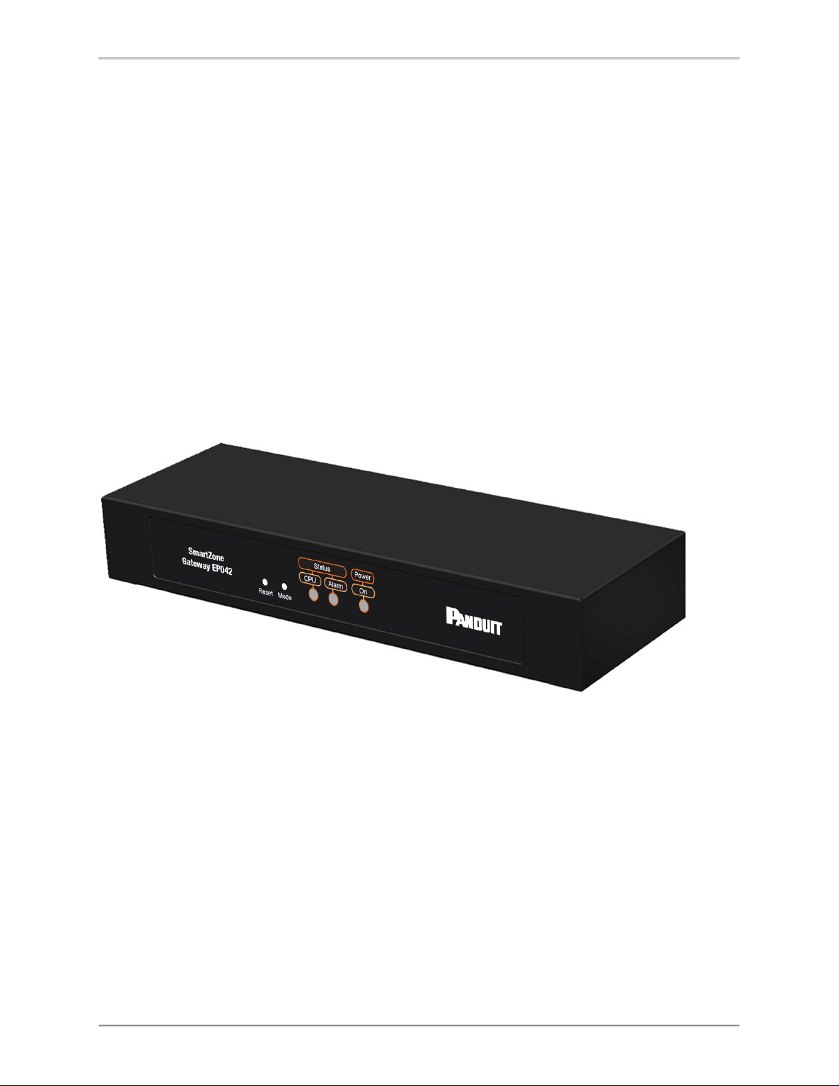
Front of Gateway EP042
LEDs
Three LEDs can be found on the front of the Gateway EP042.
l CPU: Indicates system activity.
l Alarm: Indicates that there is an alarm present on the unit.
l Power - On: Illuminates when unit is powered.
Buttons
Also found on the front of the Gateway EP042, are the following two buttons.
- 11 -
Page 12
SmartZone Gateway EP042 User Manual
l Reset: Allows the user to reboot the unit.
l Mode: The mode select switch is used to reset the unit to factory defaults.
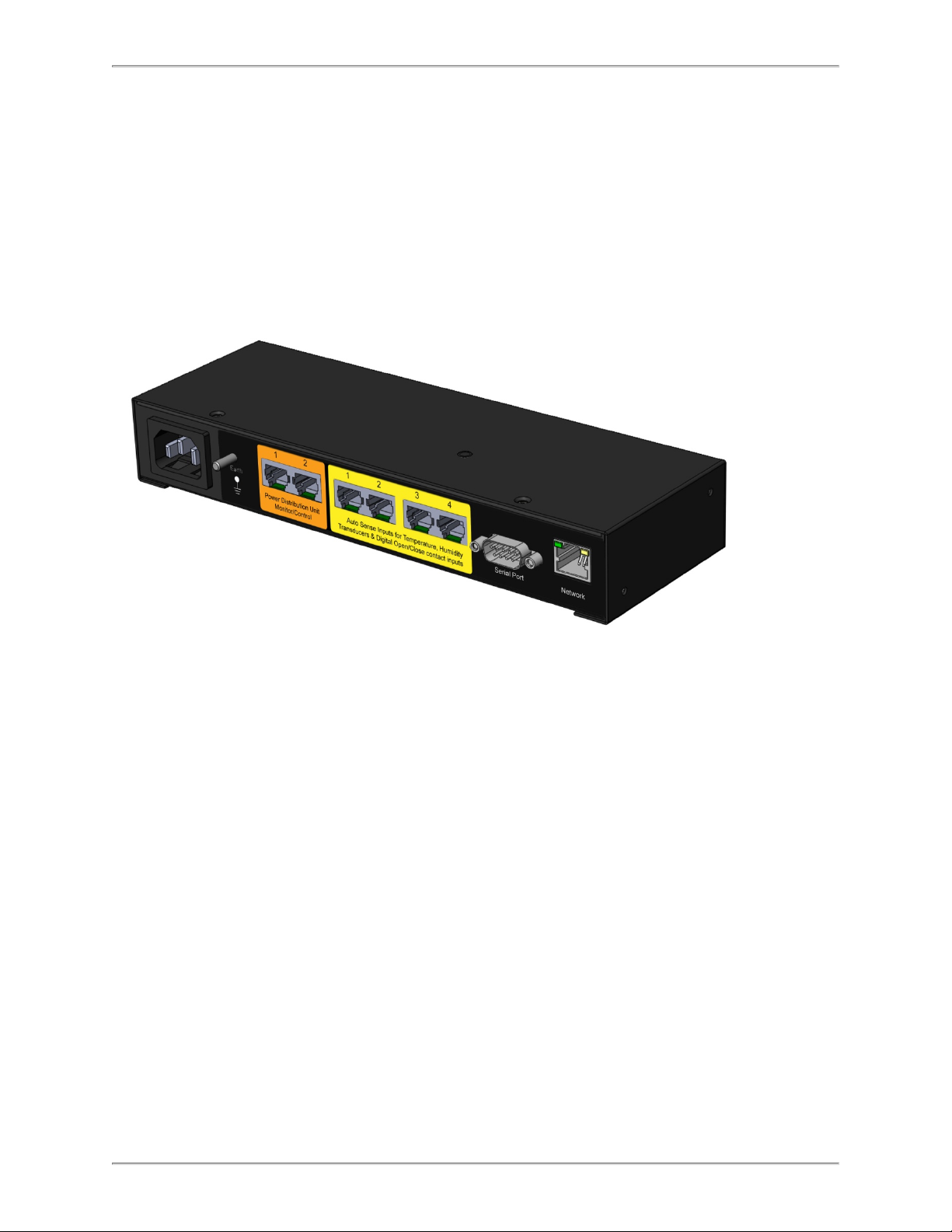
Rear of Gateway EP042
110VAC ~ 230VAC Version
The following images show the rear panel of the Gateway EP042 unit:
- 12 -
Page 13
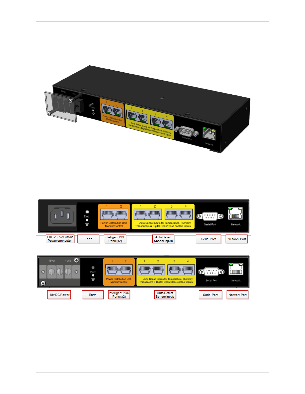
-48v DC Version
SmartZone Gateway EP042 User Manual
Ports
l Power Feed: Connection for Mains or -48v DC voltage.
l Earth: Grounding stud.
l Intelligent PDU Ports 1 and 2: Connect up to two power devices (such as Gate-
way-Enabled Rack PDUs, Inline Meters, and Clamp Meters).
- 13 -
Page 14

SmartZone Gateway EP042 User Manual
l Auto-Detect Sensors 1 through 4: Connect up to four sensors (such as Tem-
perature, Humidity, Water, Door Contacts, and more).
l Serial Port: Attach optional devices (such as an LCD Status Monitor Unit).
l Network Port: An RJ-45 connection provides Ethernet and Fast Ethernet con-
nectivity to the Gateway EP042.
- 14 -
Page 15

SmartZone Gateway EP042 User Manual
Installation Requirements
l SmartZone Gateway unit
l Main power cable (supplied)
l 10/100baseT network connection
l Network-connected computer system to setup the Gateway
l 1 x network crossover cable
l Screwdrivers
Rack Mounting
This section covers the rack-mounting of the SmartZone Gateway unit.
Additional Equipment Required
Along with the installation requirements listed above, you need a number-1 and a number-2 Phillips screwdriver to rack-mount the SmartZone Gateway unit.
Before You Begin
When determining where to install the Gateway, verify that these guidelines are met:
l Airflow around the Gateway unit is unrestricted.
l Front-panel LEDs can be easily read.
l Access to ports is sufficient for unrestricted cabling.
l AC/DCpower cord can reach the Gateway unit.
l The 10/100 network cabling does not exceed 100 meters from the Gateway unit to
the Network switch.
l Temperature around the Gateway unit does not exceed 40° C.
l Relative humidity around the Gateway unit does not exceed 90 %.
Installation Warnings
l Only trained and qualified personnel should be allowed to install, replace, or ser-
vice this equipment.
l To prevent the Gateway unit from overheating, do not operate in an area that
exceeds the maximum recommended ambient temperature of 40° C.
- 15 -
Page 16
SmartZone Gateway EP042 User Manual
l Installation of the Gateway unit must comply with local and national electrical
codes.
l To prevent personal injury when mounting or servicing the Gateway unit, ensure
that the rack or cabinet is adequately secured so that the system remains stable.
l Circuit Overloading - Consult the equipment nameplate ratings when connecting
the equipment to the supply circuit to avoid overloading of circuits, which can
adversely affect current protection and supply wiring.
l Maintain reliable grounding of rack-mounted equipment. Particular attention should
be given to supply connections other than direct connections to the branch circuit
(for example, the use of PDUs)..
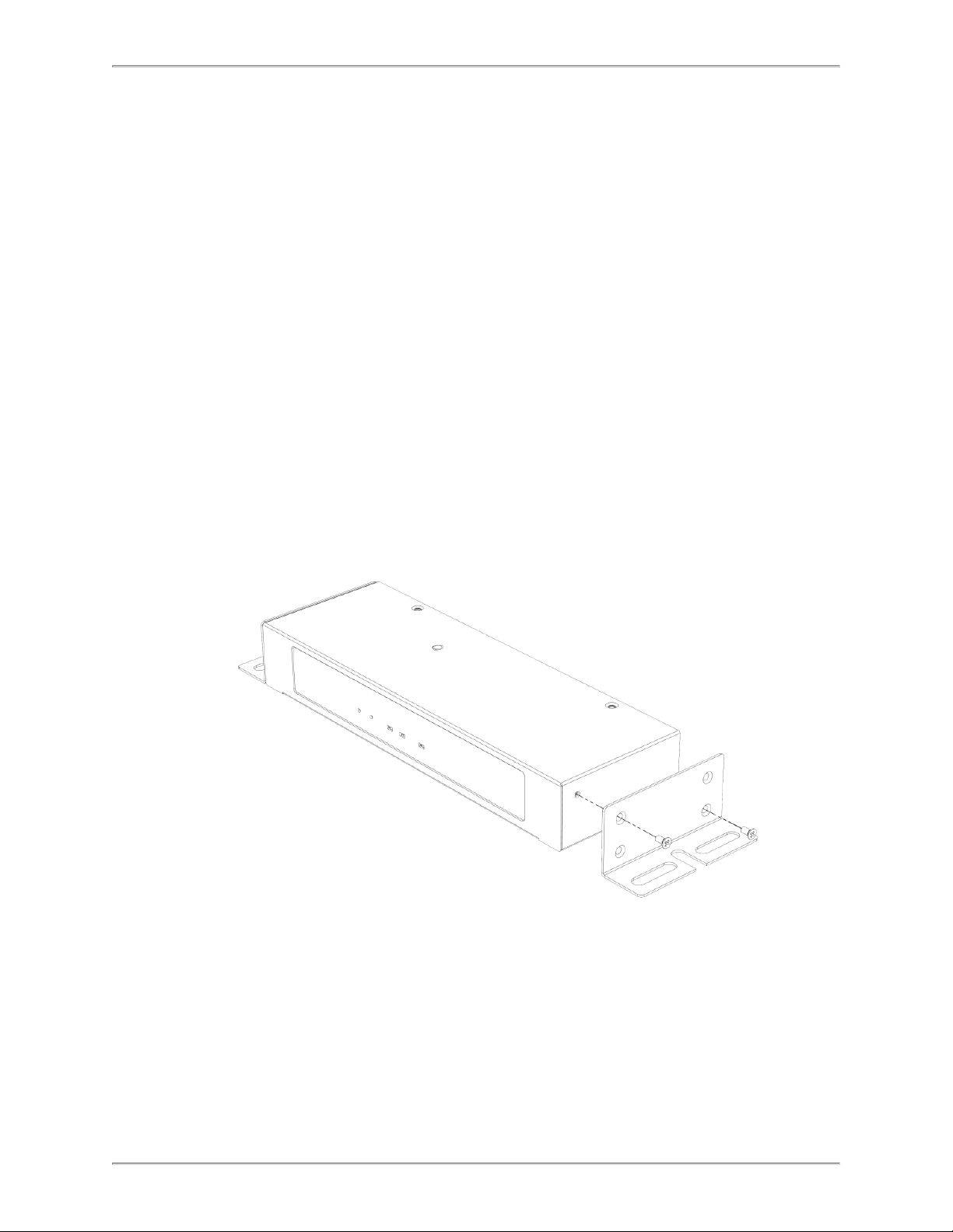
Attaching the Brackets
l The Gateway EP042 is not a full 1RU. It is recommended that the Gateway be
mounted to the rack vertically using mounting brackets.
l Using a Phillips number-1 screwdriver, use the screws supplied with the Gateway
EP042 bracket.Place the mounting bracket on the ends of the Gateway EP042
and secure using the two screws.
- 16 -
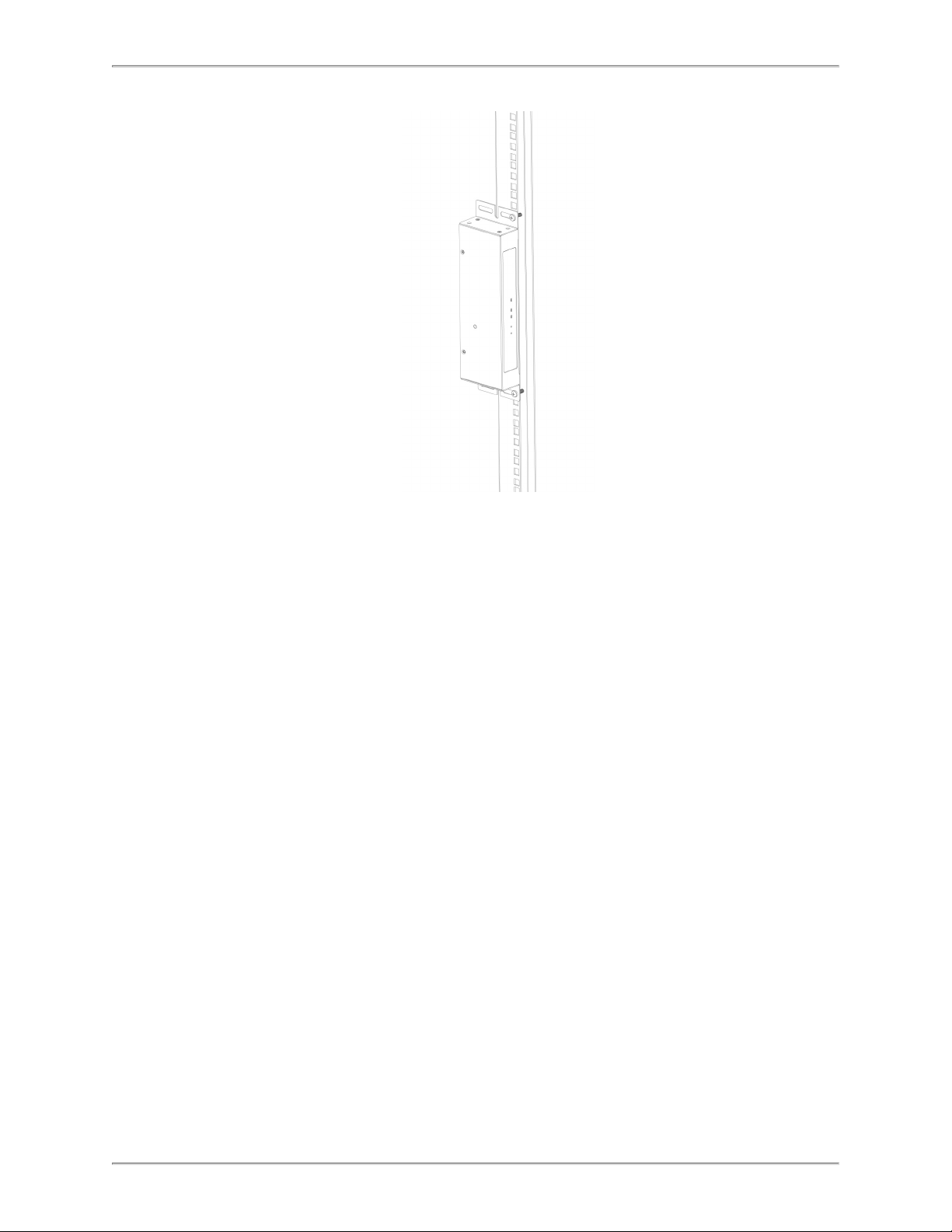
l Hold the Gateway EP042 and attach the bracket to the rack using two 12-24
screws.
Page 17
SmartZone Gateway EP042 User Manual
- 17 -
Page 18

SmartZone Gateway EP042 User Manual
Initial Setup
Default Settings
The SmartZone Gateway unit in factory default condition has the following network configuration. Advanced users may wish to make use of these settings to access the Gateway unit's Web Management Interface immediately and proceed with configuration.
Users who do not know how to do this should proceed through this section for information on how to configure the Gateway unit.
IP Address 192.168.0.253
Subnet Mask 255.255.255.0
Default Gateway 192.168.0.1
Web Management Address http://192.168.0.253/
Default username admin
Default password admin
Note: Password entries are case-sensitive.
Connecting to the Web Management Interface
The SmartZone Gateway monitoring solution can be configured entirely using the builtin Web Management Interface.
You may need to change the IP address of the PC to connect to the Web Management
Interface for the first time. The following section details how to change the IP address
and connect to the Web Management Interface.
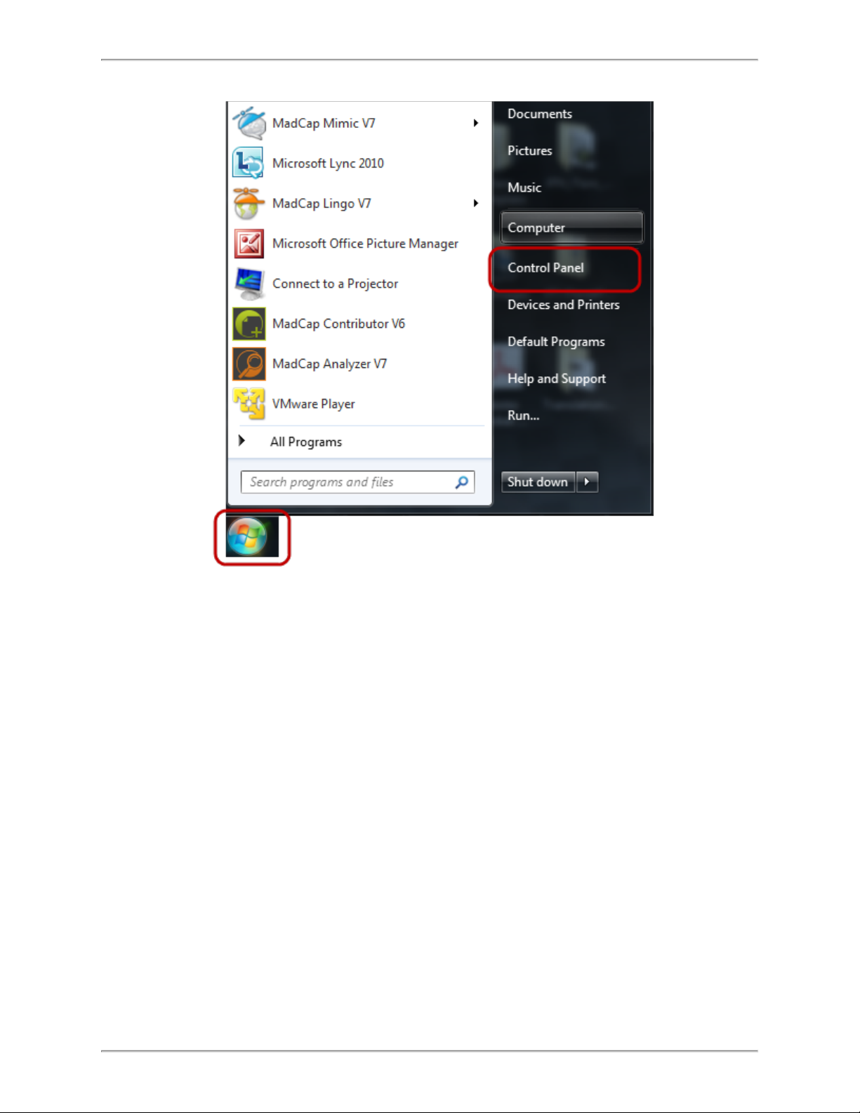
Changing your PC's IP Address
Note: Instructions refer specifically to Windows 7. Please refer to your operating system
documentation if you are not using Windows 7.
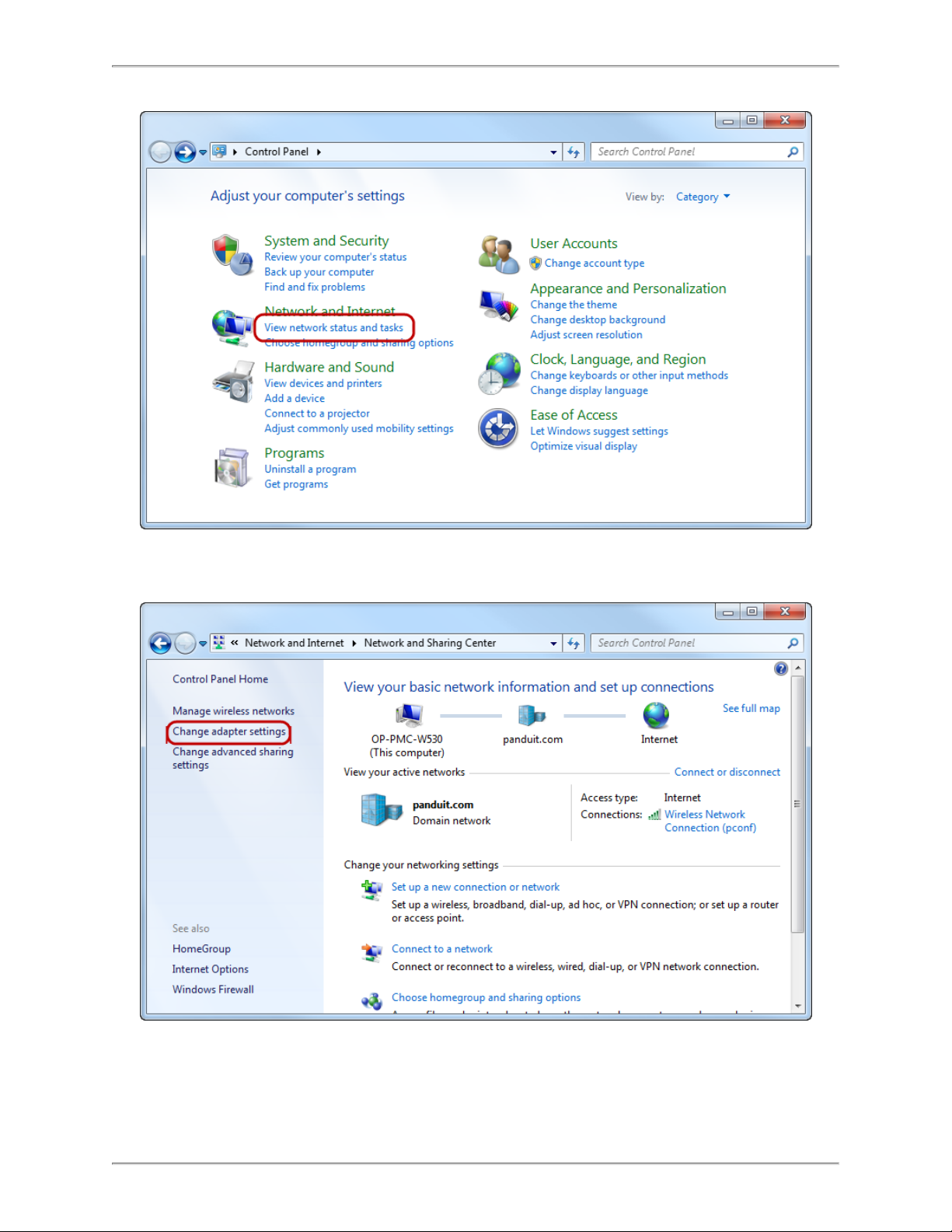
1. Click the Windows button and select Control Panel.
- 18 -
Page 19
SmartZone Gateway EP042 User Manual
2. In the Control Panel window, select View network status and tasks under the Network and Internet heading.
- 19 -
Page 20
SmartZone Gateway EP042 User Manual
3. Select Change adapter settings from the menu on the left.
- 20 -
Page 21
SmartZone Gateway EP042 User Manual
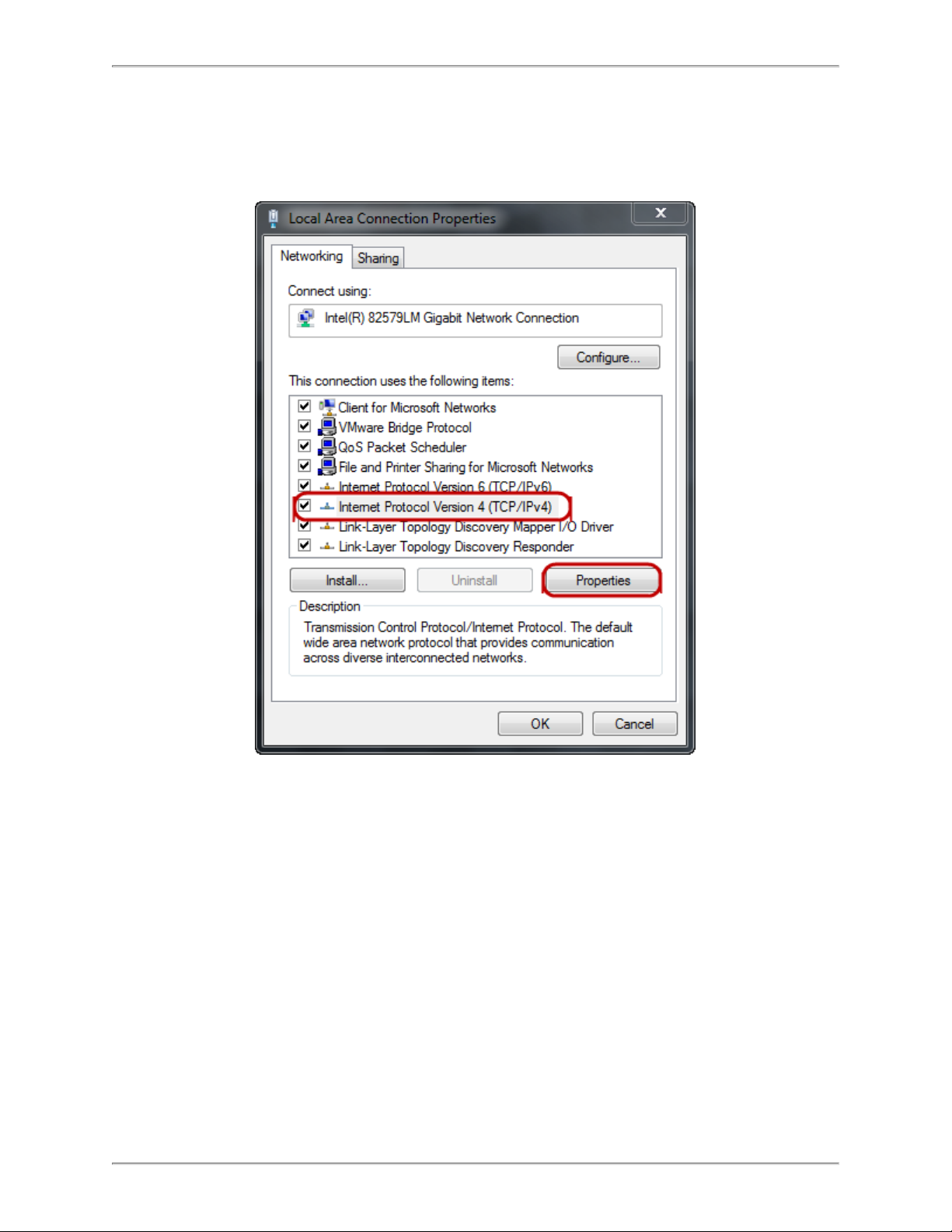
4. Select Local Area Connection.
5. Select Internet Protocol (TCP/IP) Version 4 (you may need to scroll down). Then
click the Properties button.
6. Select the Use the following IP address radio button.The Use the following
DNS server addresses radio button then selects automatically.
- 21 -
Page 22

SmartZone Gateway EP042 User Manual
Enter the following details into the appropriate boxes.
l IP address: 192.168.0.10
l Subnet mask: 255.255.255.0
l Default Gateway: 192.168.0.1
l Preferred DNS server: 192.168.0.1
7. Click OK to accept the entries.
- 22 -
Page 23

SmartZone Gateway EP042 User Manual
8. On the Local Area Connection Properties, click OK to return to the desktop.
Connecting to the SmartZone Gateway Web Management Interface
1. Connect the SmartZone Gateway unit's network connection directly to a PC's Ethernet network card using a patch cable.
Note: A crossover cable must be used when directly connecting the Gateway unitto a
PC's network card.
2. Power the Gateway unit.
3. Open a web browser.
4. Enter the following into the address bar: http://192.168.0.253.
5. The Web Management Interface loads.
- 23 -
Page 24

SmartZone Gateway EP042 User Manual
6. Click login and enter the username and password. The unit defaults are:
l Login:admin
l Password:admin
Note: Password entries are case sensitive.
- 24 -
Page 25

SmartZone Gateway EP042 User Manual
Initial Network Setup
This section provides details on preparing the unit for network access and allowing
SNMP network management.
Connection to the Web Management Interface is required.
Entering NMS Details
1. Click the Setup tab on the top menu bar then select the SNMP NMS link on the left
menu bar.
2. Enter the IP address, chosen community string, and required NMS access permissions of the Network Management Stations to be used.
3. Click Save to confirm the changes.
4. To disable an NMS, select the Disabled option from the NMS Access drop-down
list.
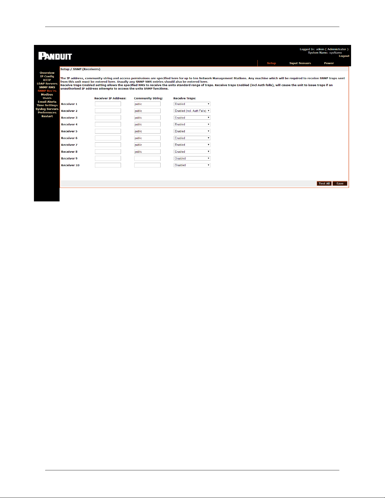
Entering Trap Receiver Details
1. Click the Setup tab on the top menu bar.
2. Select the SNMP Rec’rs link on the left menu bar.
- 25 -
Page 26
SmartZone Gateway EP042 User Manual
3. Enter the IP address, chosen community string, and required trap types for the Network Management Stations to be used.
4. Click Save to confirm the changes.
Adding Users
1. Click the Setup tab on the top menu bar.
2. Select the Userslink on the left menu bar.
- 26 -
Page 27

SmartZone Gateway EP042 User Manual
3. You can set usernames, passwords and access levels here. Unique usernames
can be set for individuals who require web management access to the Gateway
unit.
4. Click Save to confirm the changes.
Changing the Unit IP Address
1. Click the Setup tab on the top menu bar.
2. Select the IP Config link on the left menu bar.
- 27 -
Page 28

SmartZone Gateway EP042 User Manual
3. Enter the IP address, subnet mask, and the Gateway that the SmartZone Gateway
unit will use (required). Contact your network administrator if you do not know the
values that you must enter here.
Note: DHCP cannot be used for Rack Energy Kit Gateways. Select a Static
IP instead.
4. Enter the SNMP System Name, System Location , and Contact Name if
required. These fields will be added to all SNMP traps generated by the unit.
5. Click Save to confirm the changes.
6. Click Restart ,and then select Restart Now to reboot the unit and implement the
changes.
Note: Once the IP configuration has changed, the Gateway unit will no longer be accessible via the default IP address, because the new address will be operational.
7. The Gateway unit should now be connected to the main network and any further
required configuration will be done via the unit's new IP address.
- 28 -
Page 29

SmartZone Gateway EP042 User Manual
Setup - IP Configuration
The IP Config page allows you to set the SmartZone Gateway unit's own management
IP address.
System Name
You can specify the system name here. This is normally the Fully Qualified Domain
Name (FQDN) of the device, but this is not enforced.
You can retrieve the system name by querying the ‘sysName’ node via SNMP. This
allows SNMP management platforms to obtain unique names for units where specified.
The system name has no effect on network communications, and the unit will function
correctly with or without a value.
System Location
You can specify the system location here.
You can retrieve the system location name by querying the ‘sysLocation’ node via
SNMP. This allows SNMP management platforms to obtain location names for units
where specified.
- 29 -
Page 30

SmartZone Gateway EP042 User Manual
The system location name has no effect on network communications, and the unit will
function correctly with or without a value.
Contact Name
You can retrieve the unit support contact name by querying the ‘sysContact’ node via
SNMP. The contact name has no effect on network communications and the unit will
function correctly with or without a value.
IP Address
You can enter a standard IP address here. The address is entered in decimal format (for
example: 192.168.0.44 or 22.10.45.33).
The address entered here will be the address by which the Gateway unit is accessed
and managed.
Subnet Mask
The subnet mask is used to determine what part of the IP address is the network portion
and what part is the host portion.
It is often 255.255.0.0 or 255.255.255.0. The correct setting is essential for correct operation.
The subnet mask is entered in decimal format (for example: 255.255.255.0 or
255.255.0.0).
Gateway
The Gateway setting specifies the IP address of the machine/router that the Gateway
unit uses to communicate with different networks.
The Gateway address is entered in decimal format (for example: 192.168.0.1 or
11.2.24.103).
Most networks will have a Gateway. Correct setting is important for correct network communications.
Note: Once you enter the IP Configuration options and click Save, the changes take
effect. If incorrect entries are made, this may result in loss of communication. If this happens, reset the Gateway unit's network configuration. Details of how to do this can be
found in the Troubleshooting section.
- 30 -
Page 31
SmartZone Gateway EP042 User Manual
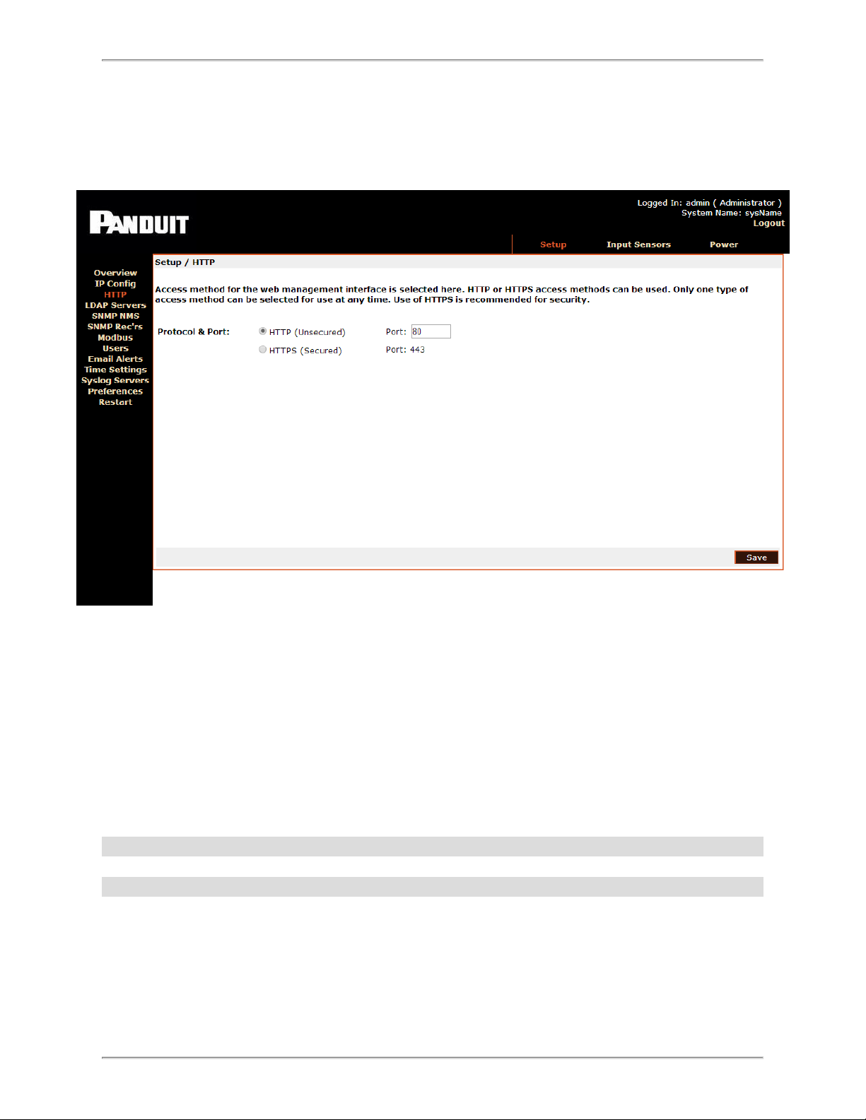
Setup - HTTP
Select the access method for the Web Management Interface here.
Both HTTP and HTTPS access modes are available by default. Selecting the HTTPS
radio button will allow only HTTPS configuration.
Use of HTTPS is recommended for security, because HTTPS will encrypt the connections.
Additionally, you can specify the TCP port for connection to the Web Management Interface here. If you have specific requirements for default ports, these can be left at their
default settings (for example, port 80 for HTTP and port 443 for HTTPS).
Note: Selecting HTTP or HTTPS requires a reboot for the selection to take effect.
Note: The Rack Energy Kit uses port 162.
- 31 -
Page 32

SmartZone Gateway EP042 User Manual
Setup – LDAP Servers
Note: LDAP information does not apply to the Gateway EP042 when used with a Rack
Energy Kit.
Lightweight Directory Access Protocol (LDAP) configuration options are specified here.
Configuration options for a Primary and Secondary server are provided with identical
configuration choices.
Disabled
No LDAP servers will be queried to verify user login credentials access and privileges.
Only internal users will be able to log in.
Primary
Only the Primary LDAP Server specified will be queried to verify user login credentials
access and privileges.
- 32 -
Page 33

SmartZone Gateway EP042 User Manual
Secondary
Only the Secondary LDAP Server specified will be queried to verify user login credentials access and privileges.
Both
Both LDAP Servers specified will be queried (with priority given to the Primary) to verify
user login credentials access and privileges.
Credential Cache
This configuration option specifies how long (in minutes) users successfully authenticated via LDAP will be allowed to access the unit without re-authenticating against
LDAP.
Display Name
You can create a display name for the specified LDAP server here. The Display Name is
for reference and logging purposes and has no direct effect on LDAP functionality.
IP Address
Specify the IP address of the LDAP server here.
Unit Base DN
You must provide the Distinguished Name (DN) of the directory object containing the
SmartZone Gateway LDAP authentication structure here. This field is required for LDAP
function.
See LDAP for configuration details.
Users Base DN 1
Provide the Distinguished Name (DN) of the directory object containing directory users
for authentication here. This field is required for LDAP function.
See LDAP for configuration details.
Users Base DN 2
You can specify the Distinguished Name (DN) of the directory object containing directory
users for authentication here. This field is optional for LDAP function providing Users
Base DN 1 has been specified.
- 33 -
Page 34

SmartZone Gateway EP042 User Manual
Setup - SNMP NMS
Specify the IP address, community string, and access permissions for up to five Network
Management Stations here.
Any machine that needs to access the unit’s SNMP functions must be entered here.
IP Address
Enter the IP address of the NMS machine here.
Community String
You must enter the required community string here. The default for many devices is public. It is recommended that the community string be changed, because it serves as an
access password.
NMS Access
Read-only access permits the NMS to use only GET commands. Read/Write access permits the NMS to use both GET and SET commands.
- 34 -
Page 35

SmartZone Gateway EP042 User Manual
Setup - SNMP Trap Receivers
Specify the IP address, community string, and access permissions for up to five Network
Management Stations here.
IP Address
You must enter any machine that is required to receive SNMP traps sent from this unit
here. Usually any SNMP NMS entries should also be entered here.
Community String
The required community string must be entered here. The default for many devices is
public. The community string should be changed, because it serves as an access password.
Receive Traps
The Receive Traps Enabled setting allows the specified NMS to receive the unit's standard range of traps. Receive Traps Enabled (incl Auth fails) will cause the unit to issue
traps if an unauthorized IP address attempts to access the unit's SNMP functions.
Receive Traps Disabled prevents traps from being sent to the specified NMS IP
address.
- 35 -
Page 36

SmartZone Gateway EP042 User Manual
Setup - Modbus
You can enable a Modbus communications protocol, specify the Modbus port number,
and enable relays control at this window.
- 36 -
Page 37

SmartZone Gateway EP042 User Manual
Setup - Users
You can add users with permission to access the Web Management Interface here. You
can specify users' access passwords and permissions.
Username
Enter the required username here. This is the name the user will have to enter to login to
the Web Management Interface.
Password
Enter access passwords on a per-user basis here.
Level
Three user levels are available for assignment.
l Administrator : Administrators have full control of SmartZone Gateway con-
figuration settings.
- 37 -
Page 38

SmartZone Gateway EP042 User Manual
l Controller : Controllers can view configuration settings.
l Viewer : Viewers can view configuration settings.
Warning: User 1 / admin is the master administrator. It is possible to remove administrator rights from the admin user. Doing this is not recommended, because it may result
in no one having administrator access. In this situation, a reset to factory defaults is the
only solution. Details on how to do this can be found in the Troubleshooting section.
Setup - Email Alerts
On this page, you can edit email alert settings for traps. You may set up to 10 email
receivers.
Email Alerts
SMTP Relay Server The IP Address of the SMTP Server
From Address Address from which the alert emails are sent
Reply-To Address Address to which the email receivers can reply
Destination Address Address that will receive the email alerts
Enabled Toggle the check box to enable or disable alerts to each address
Repeat Timer Number of minutes after which the email alert will repeat
- 38 -
Page 39

SmartZone Gateway EP042 User Manual
Setup - Time Settings
The Time Settings page allows you to view or edit the current date and time.
Select the correct day, month, and year from the dropdown menus, and verify the local
time. If you want to change the time, you must check the Update time checkbox.
Time Adjustments
Select the correct time zone from the drop-down menu.
l Daylight Saving can be enabled or disabled by clicking the check box. If Daylight
Saving is enabled, select start/stop dates from the subsequent drop-down menus.
l Date Format allows the administrator to choose whether the date is displayed with
the day or month first. For example, the date August 20, 2013 can be displayed in
one of two ways:
20/08/2013 (DD / MM / YYYY)
or
08/20/2013 (MM / DD / YYYY)
Select the desired format from the dropdown menu.
- 39 -
Page 40

SmartZone Gateway EP042 User Manual
l SNTP Servers - Simple Network Time Protocol synchronizes the clocks of com-
puter systems over a network. Enter the IP address of an SNTP server, and specify
(in hours) how often the time should be updated.
Setup - Syslog Servers
This page allows you to view or edit information about the Syslog Servers currently
being used.
From the Enabled drop-down menu, you can choose which syslog servers are enabled.
Fill in the following fields for each Syslog server.
Syslog Server Setup
Display Name The name of the Syslog server
IP Address The IP address of the Syslog server
Port The number of the port being used
Log Event Types Click the check boxes to choose which events to log
Setup - Preferences
The Preferences page allows you to edit system preferences.
- 40 -
Page 41

SmartZone Gateway EP042 User Manual
Preferences
From the dropdown menu, select the first page you want to open
Default Page
when a user logs in. The preset default page is the Overview
page.
Choose from the dropdown menu where the timestamp will be
found on traps. There are three options:
Time stamp Traps
l Prefix – timestamp at the beginning
l Append – timestamp at the end
l None – no timestamp
User Session
Timeout
Enter a number of minutes, after which a session will be timed
out if the user is inactive.
Temperature Scale Select Celsius, Fahrenheit, or Kelvin from the drop-down menu.
Page Refresh Period
Enter a number of seconds, after which the page will auto matically refresh. If 0 is entered, the page will not refresh automatically.
Setup – Restart
A unit may be rebooted or reset to factory defaults here.
- 41 -
Page 42

SmartZone Gateway EP042 User Manual
Restart Unit
Restart Now
Selecting Restart Now commands the unit to reboot. Rebooting the unit will cause any
outstanding configuration changes to take effect.
Reset to Factory Defaults
See Troubleshooting for instructions on resetting the factory default settings for the unit.
- 42 -
Page 43

SmartZone Gateway EP042 User Manual
Sensor Inputs – Configuration and Status
Status
The Input Sensors status page presents an overview of the input ports. This page displays the input channel number, name, type of input sensor, status, current readings, and
thresholds.
Status Indicators
Three status indicators are displayed next to the input channels to allow quick determination of normal, warning, and critical alarm statuses:
Channel reading currently within threshold limits.
Upper or lower Warning limit reached/exceeded.
Upper or lower Critical limit reached/exceeded.
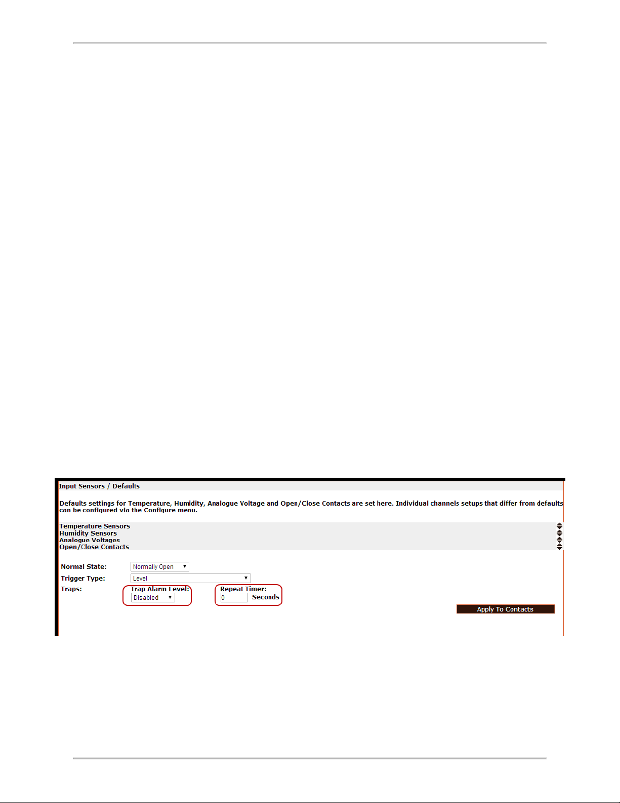
Input Sensors – Defaults
The Input Sensor Defaults menu allows configuration parameters for input sensors of
specific types to be defined and applied to all inputs of that type.
The types of input sensors are:
- 43 -
Page 44

SmartZone Gateway EP042 User Manual
l Temperature
l Humidity*
l Analog (Voltage)
l Open/Close Contacts (digital inputs)
*Note: Rack Energy Kits do not support humidity sensors.
The configurable defaults are described below.
Calibration Offset
The value entered here alters the actual reading of a sensor by the amount specified.
For example, if a Calibration offset of 6 was used and a sensor's true reading was 36,
the indicated reading used for display and alarm purposes would be 42. This works the
same way for both temperature and humidity sensors.
Hysteresis Value
The hysteresis default value to be applied to sensors is specified here. The value specified is an offset from a sensor's threshold values.
For example, a hysteresis value of 5 would mean that, in the case of an Upper Control
Limits alarm, the alarm value would have to reduce to 5 below the threshold value before
another alarm is issued.
- 44 -
Page 45
SmartZone Gateway EP042 User Manual
Please see Appendix B: Hysteresis Demystified for detailed information.
Limits and Traps
You can set default values for sensor alarm thresholds here. You also can set the default
settings for alarm threshold traps here.
The following thresholds can be set:
l Upper Control Limit
l Upper Warning Limit
l Lower Control Limit
l Lower Warning Limit
You can apply default trap settings for all of these thresholds. With the trap box deselected, no SNMP alarm traps will be generated, even when an alarm condition exists for
that threshold.
Repeat Timer
The repeat timer causes alarm traps to be reissued after a specified amount of time if the
alarm condition persists.
Setting the repeat timer to 0 will disable the repeat traps.
The defaults that can be set for Open/Close contacts differ from the Temperature and
Humidity settings.
- 45 -
Page 46

SmartZone Gateway EP042 User Manual
Normal State
Normal state specifies the condition in which a contact is considered to be in a Normal,
Non-alarmed state.
Devices such as smoke alarms and air conditioning units often have normally open contacts. To receive alarm indications from these types of units would cause alarms to be
issued when a monitored contact closes.
Setting normally closed in the case of a rack or cabinet door would cause an alarm condition when the door was opened.
Trigger Type
The trigger type defaults for Open/Close sensors are specified here.
The three available options for trigger types are:
Level
Level triggering is the default mode. When an input physically transitions from a Normal
to Non-Normal state, an alarm is triggered. However, the alarm persists only while the
input remains in a Non-Normal state. When the input returns to a normal state, the alarm
is cleared.
Normal to Non-Normal (Positive Edge)
This type of triggering may be used in situations where a momentary type input (for
example,: a shock sensor or PIR) is used. Since these types of inputs are momentary,
any alarm condition that occurs will persist until manually cleared.
Positive Edge triggering is used when an alarm is required to persist after an input
changes from the Normal state to the Non-Normal state.
Non-Normal to Normal (Negative Edge)
This type of triggering may be used in situations where a momentary type input (for
example, a shock sensor or PIR) is used. Since these types of inputs are momentary,
any alarm condition that occurs will persist until manually cleared.
Negative Edge triggering is used when an alarm is required to persist after an input
changes from the Non-Normal to the Normal state.
- 46 -
Page 47
SmartZone Gateway EP042 User Manual
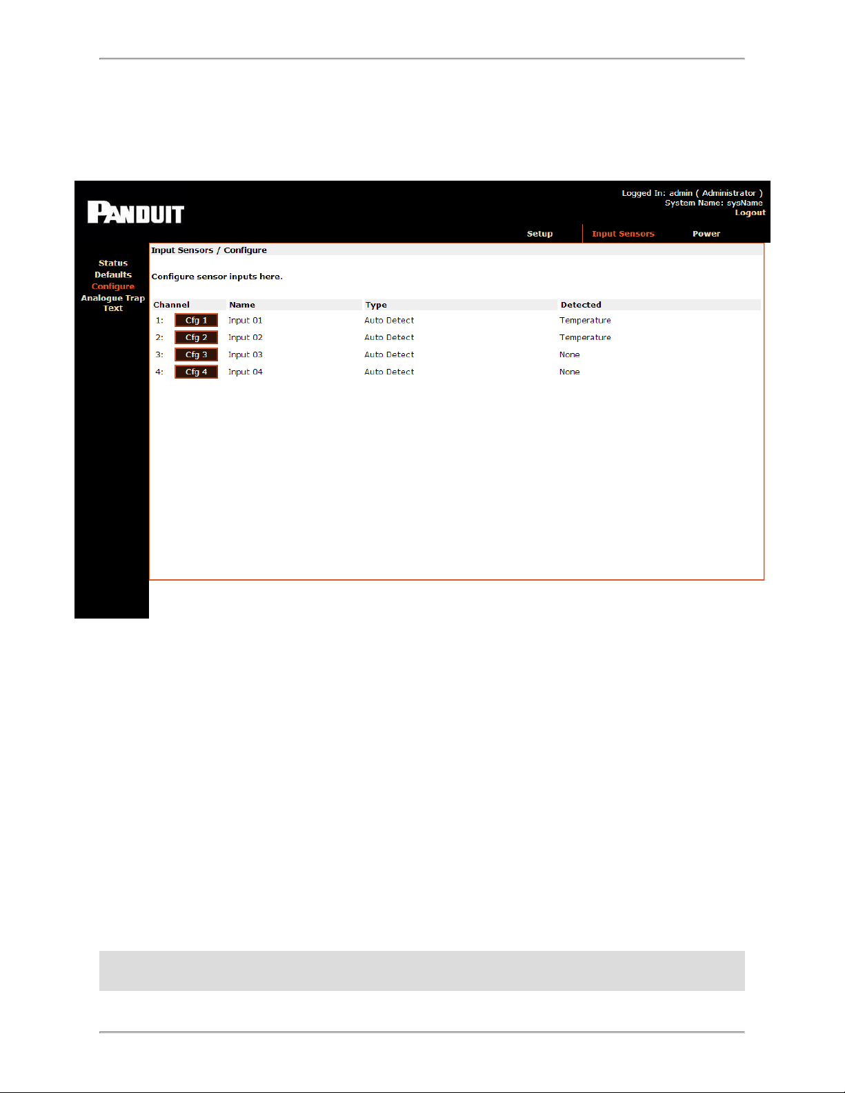
Input Sensors - Configure
You can configure the individual sensor channels in this window.
Select the Config option to open a detailed configuration page for the selected sensor.
The difference between the menus presented here and the menus presented on the
Defaults page is that settings are applied to individual channels.
The submenus contain all the options in the Defaults menu, plus two additional options:
Name
Sensor channels can be assigned names for ease of identification (for example, “Server
Room Sensor” or “UPS Battery Fail”).
Type
The type of connected sensor is specified here. The sensor channels can be set to auto
detect, temperature, humidity, contact, or disabled.
Note: Occasionally, clear traps will be sent to the NMS trap receivers while a sensor is
being connected to a device. This is considered normal behavior, because some voltage
- 47 -
Page 48

SmartZone Gateway EP042 User Manual
surges may be produced when input sensors are physically connected to the gateway.
In normal operation, the sensors will always be connected to the device and the sensor
voltages will stay within normal expected values
- 48 -
Page 49

SmartZone Gateway EP042 User Manual
PDUs – Configuration and Status
PDU Status
The PDU Status page presents an overview of connected SmartZone Rack PDUs. The
page displays the PDU channel number, name, voltage, and current thresholds.
Status Indicators
Three status indicators are displayed next to PDU channels to allow quick determination
of normal, warning, and critical alarm statuses:
- 49 -
Page 50

SmartZone Gateway EP042 User Manual
Channel reading currently within threshold limits.
Upper or lower Warning limit reached/exceeded.
Upper or lower Critical limit reached/exceeded.
Configuring PDUs
The PDU Configuration menu provides the ability to configure individual PDU options.
You can configure the two PDU channels individually by selecting the Config option
next to each channel.
A summary of several current configuration parameters is displayed on a per-PDU channel basis.
- 50 -
Page 51

SmartZone Gateway EP042 User Manual
Control Method
The Control Method parameter specifies which control methods are available to control
the outlets on PDUs attached to the unit.
HTTP + SNMP
The Web Management Interface and SNMP can be used to command PDU outlets.
HTTP Only
This option allows only the Web Management Interface to command PDU outlets. This
effectively disables SNMP PDU outlet control.
SNMP Only
This option allows only SNMP to command PDU outlets.
This effectively disables the Web Management Interface PDU outlet control.
RS232 Only
This option allows PDU control commands to be issued directly to a unit via the onboard
RS232 port. This option disables the Web Management Interface and SNMP control.
Cycle Up/Down Delay
This parameter specifies the interval in seconds between switching on and switching off
outlets when an entire PDU is cycled (all outlets commanded on or off).
Repeat Timer (on Comms Failure)
This parameter specifies the interval in seconds between when an initial PDU comms
failure trap is produced and a repeat trap is issued.
Reboot Delay
This parameter specifies how long (in seconds) an outlet remains off after a reboot
before switching back on.
Abort Cycle Delay
This parameter specifies how many seconds must elapse before a commanded cycle
begins on a PDU. This delay gives the user time to reverse the decision to cycle a PDU
before any outlet states are changed.
- 51 -
Page 52

SmartZone Gateway EP042 User Manual
If you do not want to use this functionality, set the delay to zero.
Power – Configure Menu
This menu allows all the available options for a specific PDU to be specified.
Name
Individual PDUs can be assigned names for ease of identification (for example, “Rack 5
PDU Sensor” or “Comm Room”).
Type
Specify the type of PDU connected to a channel.
Disabled
No monitoring or control will be performed on this PDU channel.
Monitor Only
The monitoring of power values will be performed on this PDU channel.
- 52 -
Page 53

SmartZone Gateway EP042 User Manual
Monitor and Control
Both outlet control and power monitoring will be enabled on this PDU channel.
Per Outlet Monitor
This option enables PDU-level monitoring and monitoring of each individual PDU outlet.
Per Outlet Monitor and Control
This option enables PDU-level monitoring and monitoring of each individual PDU outlet,
plus outlet control.
Number of Outlets
This parameter specifies the number of controllable outlets present on a PDU. This is
required when the Control Only or Monitor and Control options have been selected.
For example, if you have a PDU consisting of 24 Outlets, one of which is a permanent
live (non-switching) outlet, 23 outlets would be specified.
Warning: Failure to specify the correct number of outlets can lead to the incorrect outlet
being switched on or off.
During unit setup and deployment, you should select the Control Only or Monitor and
Control options before critical loads are connected to outlets.
Cycle Password
This field specifies the password required to set a power cycle of outlets on a controllable strip. This password is used when switching outlets using SNMP, not when
switching via the web interface.
Power on Mode
In the event that power to the PDU is lost, this parameter specifies how the outlets will be
switched back on once power is restored.
RMS Volts
Repeat Timer
In the event of a communications failure with a connected PDU, this entry specifies how
often (in seconds) Comm Fail traps will be generated.
Limits and Traps
You can specify values for voltage, current, and total power thresholds here. You also
can enable or disable traps for each threshold.
The following thresholds can be set:
- 53 -
Page 54

SmartZone Gateway EP042 User Manual
l Upper Control Limit
l Upper Warning Limit
l Lower Warning Limit
l Lower Control Limit
Note: There are no lower limits for total power, because total power consumption can
only go up, not down.
RMS Current
(See options for RMS Volts above)
Total Power
(See options for RMS Volts above)
PDU Outlets
(See options for RMS Volts above)
PDUs – Control
Individual outlets or all outlets on a given PDU can be switched on and off using this
screen.
- 54 -
Page 55

SmartZone Gateway EP042 User Manual
The display consists of a visual representation of PDUs that have Control or Monitor
and Control enabled on the Configure page.
PDUs that are Disabled or in Monitor Only status do not display any outlet graphics
and are displayed with appropriate text.
PDU inputs are numbered 1 to 2 in ascending order. PDU numbers correspond to the
physical input ports on the rear of the SmartZone Gateway unit.
Switching Individual Sockets
When you click on a socket, a control menu above the socket displays further information. Three control options are also presented:
On
Selecting this option commands the selected outlet to switch On.
If the outlet is already on this will have no effect.
Off
- 55 -
Page 56

SmartZone Gateway EP042 User Manual
Selecting this option commands the selected outlet to switch Off.
If the outlet is already off this will have no effect.
Reboot
The reboot option commands the selected outlet to switch off. After the time specified by
the Reboot Delay timer has elapsed, the outlet will automatically switch itself back On.
Switching an Entire PDU
You can switch all the outlets on any PDU Off or On with a single command by clicking
the Lightning Bolt symbol on the end of a PDU graphic.
A small dialog displays, offering the following options:
On
This option commands all outlets on a selected PDU to switch on. Any outlets already
on will remain on; any currently off will be switched on.
Off
This option commands all outlets on a selected PDU to switch off. Any outlets already off
will remain off; any currently on will be switched off.
Abort!
Once a command has been issued to turn all of a PDU's outlets on or off, you can click
the Abort! button to abort the command.
The Abort Cycle delay option on the PDU – Configure – Config menu specifies the time
allowed in seconds for an abort to be issued.
LDAP
Note: LDAP information does not apply to the Gateway EP042 when used with a Rack
Energy Kit.
SmartZone Gateway LDAP Overview
The SmartZone Gateway unit implements a Lightweight Directory Access Protocol
(LDAP) client. This allows the Gateway unit to authenticate user logins to the Web Management Interface using an LDAP Directory.
If LDAP is used for authentication, it is first consulted when a user attempts a login. If the
user is not found or access is denied by LDAP, then the credentials are checked against
the Gateway unit internal user list.
- 56 -
Page 57

SmartZone Gateway EP042 User Manual
Note: Anonymous LDAP lookups are not supported.
Note: Configuration of LDAP is an advanced topic and requires existing knowledge of
LDAP function and setup.
SmartZone Gateway LDAP Structure
For a Gateway unit to successfully authenticate a user for a Web Management Interface
login, it needs to be pointed to a specific structure within a directory. You can point a unit
to this structure within a directory by specifying the Unit Base DN on the Network Setup
– LDAP page.
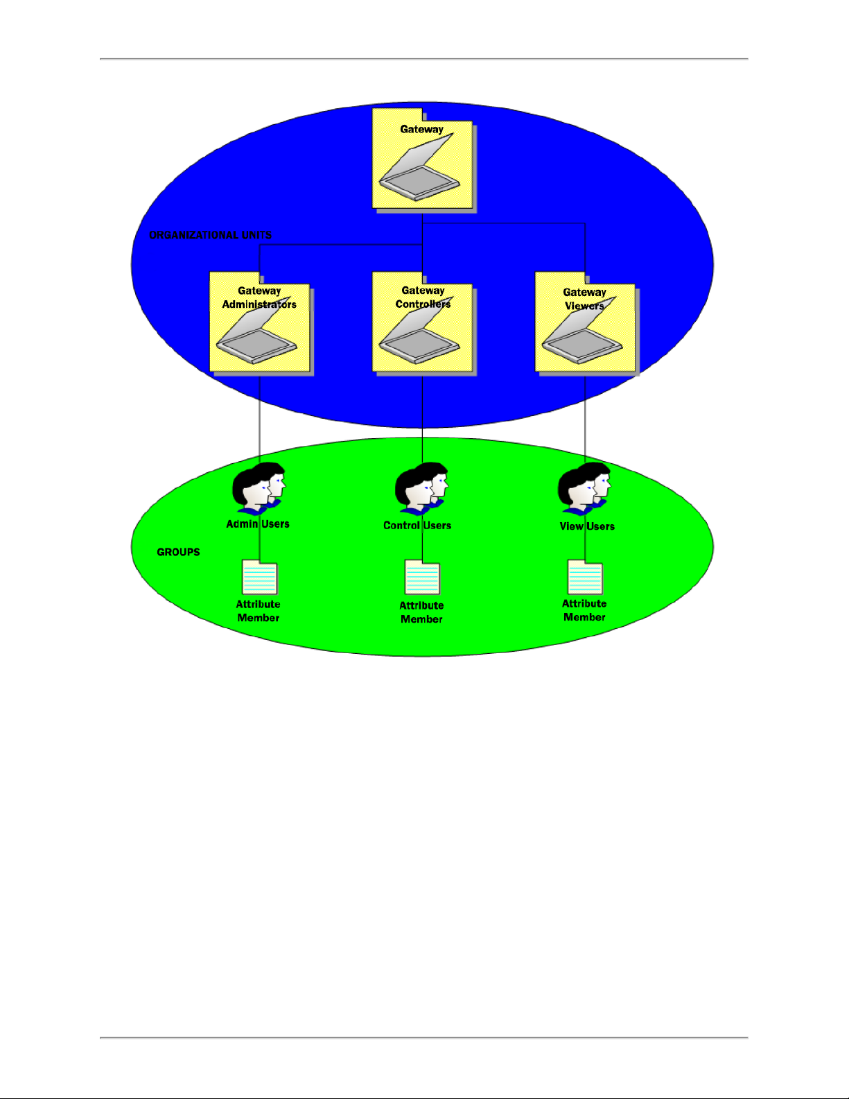
You will need to create the following Organizational Units:
l Gateway (this can be named anything)
l Gateway Administrators
l Gateway Controllers
l Gateway Viewers
Note: Groups are found in the Active Directory schema. However, any implementation
which provides a group with a Members attribute may function.
The following figure depicts the Gateway LDAP authentication structure:
- 57 -
Page 58
SmartZone Gateway EP042 User Manual
Once the required LDAP structure has been created, the Distinguished Name (DN) of
users should be added to either:
l Gateway AdminUsers
l Gateway ControlUsers
l Gateway ViewUsers
Group Membership and Access Level
Membership in these groups grants the following permissions on Gateway units:
Gateway AdminUsers
Users placed into this group will have Admin privileges on Gateway units.
- 58 -
Page 59

SmartZone Gateway EP042 User Manual
Gateway ControlUsers
Users placed into this group will have Controller privileges on Gateway units.
Gateway ViewUsers
Users placed into this group will have View privileges on Gateway units.
SmartZone Gateway Unit Configuration
For LDAP authentication to function, you need to provide certain configuration values for
each Gateway unit.
To enter the configuration values, perform the following steps.
1. If one LDAP server is to be used, select Enabled – Primary.
2. Enter a descriptive name (for example, AD_Server_1) into the Display Name (DN)
field.
3. Enter the complete DN of the top level OU.
4. Enter the DN of where users that are members of Gateway access groups can be
found in the Directory. These DNs can be entered into User Base DN 1 and User
Base DN 2.
- 59 -
Page 60

SmartZone Gateway EP042 User Manual
5. Click Save.
- 60 -
Page 61
SmartZone Gateway EP042 User Manual
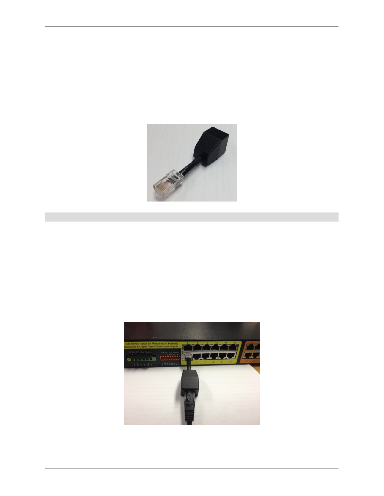
Temperature Sensor Adapter Installation
Follow the instructions below to install the ZAHTLADT-02 v1.01.01 temperature sensor
adapter module. This adapter allows legacy sensors to provide more accurate temperature readings.
Note: This adapter does not work with the ZETHL-14 temperature sensor.
New Installations
Follow these instructions when you are installing a standard temperature sensor, but the
upgraded sensor input is required.
1. Plug the adapter directly into the back of the gateway, at the sensor port to be used
for temperature.
2. Plug the temperature sensor connector into the adapter.
3. Update the gateway firmware to the latest release.
- 61 -
Page 62

SmartZone Gateway EP042 User Manual
Existing Installations.
Follow these instructions when the sensor is already installed along with the gateway.
1. Unplug the current temperature sensor from the gateway, noting the location where
it resided.
2. Insert the adapter into that location.
3. Plug the sensor into the end of the adapter.
4. Perform these steps for all other temperature sensors to be changed.
5. The gateway firmware must be updated to the latest firmware.
Before the adapter is fitted:
After the adapter is fitted:
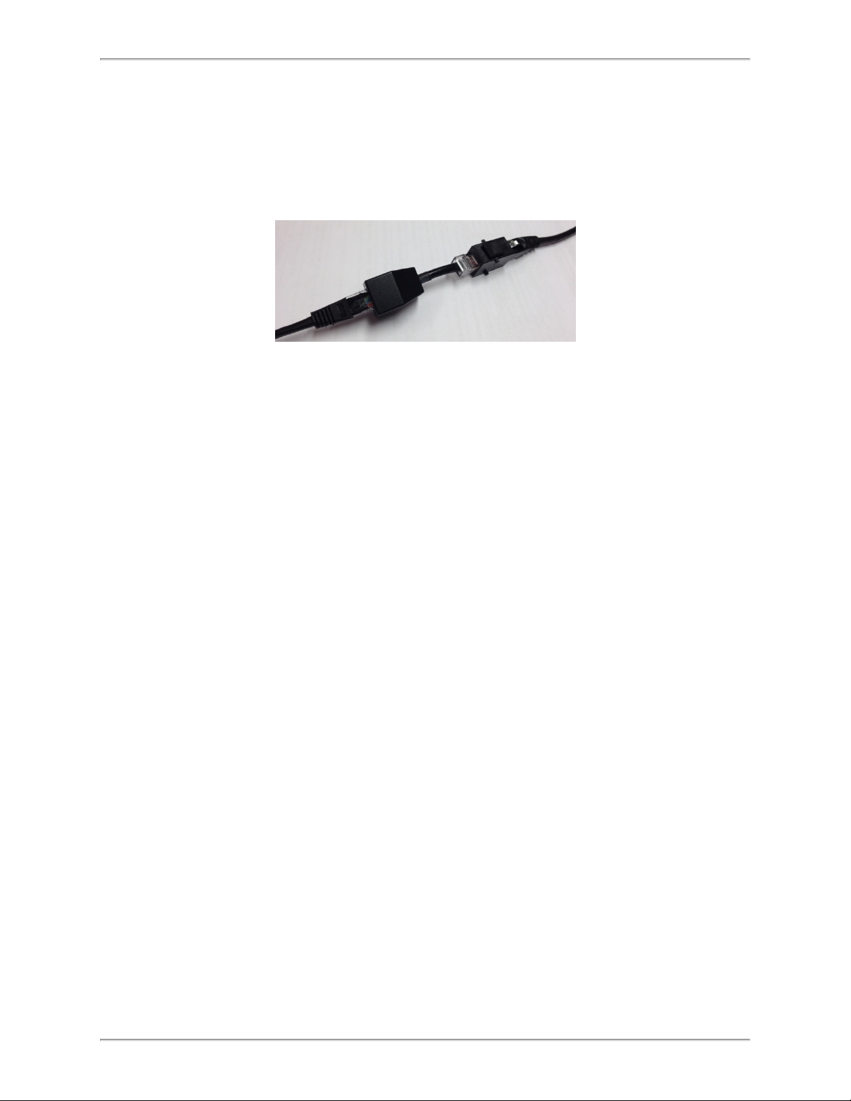
Fitting the Adapter In-line.
This procedure is not recommended, but it may be the only solution in some cases.
- 62 -
Page 63
SmartZone Gateway EP042 User Manual
1. Using a patch lead from the gateway and an RJ45 Jack to Jack through connector
on its non-gateway end, plug the adapter RJ45 Plug into the through connector.
2. Plug either the RJ45 plug of a temperature sensor into the jack on the adapter or a
patch lead with the temperature sensor on the end.
- 63 -
Page 64

SmartZone Gateway EP042 User Manual
Troubleshooting
Resetting the SmartZone Gateway to Factory Default Settings
To reset the Gateway unit to factory defaults, perform the following steps:
1. Press and release the Reset button on the front of the unit. The Alarm LED will
flash twice (off/on, off/on).
2. Immediately press and hold the Mode button until the alarm LED goes off.
3. Immediately press and release the Reset button.
NOTE: The unit will now restart. The Status LED will start flashing after around 1 minute.
The reset process is complete, and the IP address is set to the default 192.168.0.253.
Problem: The NMS Cannot Poll the SmartZone Gateway Unit
l Solution:Make sure the network is properly connected to the Gateway unit.
l Solution:Make sure the cable is in good condition.
l Solution:Try pinging the Gateway unit from another computer on the same net-
work segment as the Gateway unit.
l Solution:Ensure that the NMS IP Address is in the NMS table of the Gateway unit.
l Solution:Ensure that the community string has been set for the NMS via the Web
Management Interface.
- 64 -
Page 65

SmartZone Gateway EP042 User Manual
Technical Support
For technical support for the SmartZone Gateway system, please contact Panduit Technical Support using one of the following methods:
l 1-866-721-5302 (toll-free)
l Orland Park, USA: 6:30 a.m. – 8:00 p.m. CST
l Mumbai, India: 6:30 a.m. – 5:00 p.m. IST (8:00 p.m. – 6:30 a.m. CST)
l On Call Support on Weekends
l systemsupport@panduit.com
- 65 -
Page 66

SmartZone Gateway EP042 User Manual
Appendix A: Technical Details
Factory Default Settings
IP Address 192.168.0.253
Subnet Mask 255.255.255.0 (/24)
Default Gateway 192.168.0.1
Web Management Address http://192.168.0.253/
Default username admin
Default password admin
Operating Information
Input Power
Input Power 36 to 60 VDC 0.5 Amp Maximum
Operating Temperature 0OC to 40OC
Storage Temperature -10OC to 70OC
Operating Humidity 5% to 90% Relative Humidity
Storage Humidity 5% to 100% Relative Humidity
CAUTION: There is a risk of explosion if the battery is replaced by an incorrect type. Dispose of used batteries according to the instructions.
100 to 240VAC 50Hz / 60 Hz
0.5 Amp Maximum
- 66 -
Page 67

Unit DimensionsAC)
Height 37mm [1.5” ]
Width 233mm [9.2” ]
SmartZone Gateway EP042 User Manual
Depth: (including earth stud and
connectors)
DepthL (Case only) 79mm [3.1” ]
Width including Mounting brack-
ets
Unit net weight 760gm [26.8 oz]
85.2mm [3.4” ]
285mm [11.2” ]
Unit Dimensions (-48VDC)
Height 37mm [1.5” ]
Width 242.6mm [9.6” ]
Depth: (including earth stud and
connectors)
DepthL (Case only) 80.4mm [3.2” ]
104.4mm [4.1” ]
Width including Mounting brack-
ets
Unit net weight 828gm [29.2 oz]
295mm [11.6” ]
- 67 -
Page 68

SmartZone Gateway EP042 User Manual
Appendix B: Hysteresis Demystified
When a temperature or humidity limit is reached and the relevant limit has its OFF to ON
Trap enabled, an alarm trap is issued by the SmartZone Gateway unit.
With a zero hysteresis setting, the traps will continue to be generated each time the limit
is reached.
This may be undesirable in a situation where the temperature or humidity level measure
has reduced by only a small amount before rising again and triggering further traps.
The hysteresis function is provided to prevent further alarm traps from being generated
until the measured value has fallen to a satisfactory level.
As shown in image above, the humidity first rises past its upper warning threshold, which
generates an alarm trap.
The humidity then reduces slightly but does not reduce to the hysteresis level, which is
1.5% relative humidity lower than the alarm setting (1.5% relative humidity lower as an
absolute measured value, rather than 1.5% of currently measured value).
Humidity then increases and decreases again. However, on the second decrease of
humidity the level drops below the hysteresis level. The Humidity falling below the hysteresis level re-enables alarm traps for the next alarm event. An upper limit of 25 and a
hysteresis threshold of 1.5 yield a threshold limit of 23.5.
The humidity level again begins to rise and again exceeds the upper limit, however this
time an alarm trap is generated again.
- 68 -
Page 69

SmartZone Gateway EP042 User Manual
The Hysteresis feature acts on the following Temperature and Humidity thresholds:
l Upper Control Limit (UCL)
l Lower Control Limit (LCL)
l Upper Warning Limit (UWL)
l Lower Warning Limit (LWL)
The inverse of the above description is true when applied to Temperature and Humidity
lower control and warning limits.
You can configure the hysteresis threshold by using the menu options.
- 69 -
Page 70

SmartZone Gateway EP042 User Manual
Appendix C: Encryption and Security
The Gateways support HTTPSencryption, and they support the following cipher configurations.
l TLS_RSA_WITH_3DES_EDE_CBC_SHA
l TLS_RSA_WITH_DES_CBC_SHA
l TLS_RSA_WITH_AES_128_CBC_SHA
l TLS_RSA_WITH_AES_256_CBC_SHA
- 70 -
 Loading...