

Page 1
Part No. CT-1701
OPERATION INSTRUCTIONS
Contour Crimp
CONTROLLED CYCLE
CRIMPING TOOL
Crimps Panduit #10 - #2 AWG
non-insulated P series terminals and
#14 - 10 AWG copper
code conductor lugs.
Includes 5-position, rotating die.
Provides UL Listed and CSA Certified terminations
with applicable Panduit terminals.
COPPER COMPRESSION CONNECTOR
CRIMPING INSTRUCTIONS
1. With the handles in the open position,
depress die release and rotate die to desired
pocket. The pocket will lock in place when
an audible “click” is heard (Die index number
appears to the left of corresponding pocket).
CAUTION: Do not cycle tool unless the
die release button has seated and the die
has locked in place.
Refer to product packaging for selection of
the proper crimp pocket. Place the desired
compression connector in the crimp pocket
(See Fig. 2).
2. Close handles until the connector is held
snugly in position—do not deform the
barrel.
3. Insert the stripped wire into the connector
until the wire stops. Refer to product
packaging for wire strip length.
4. Crimp the connector by closing the handles
until the controlled cycle mechanism
releases. Repeat this operation for the
compression connectors that require more
than one compression. Upon release, the
handles will open automatically and the
crimped connector can be removed.
After crimping, inspect that the crimp is
centered on the barrel in order to achieve
optimal pullout performance.
OPERATION INSTRUCTIONS
PA23829A01
Rev.: 03 1-2011
CT-1701
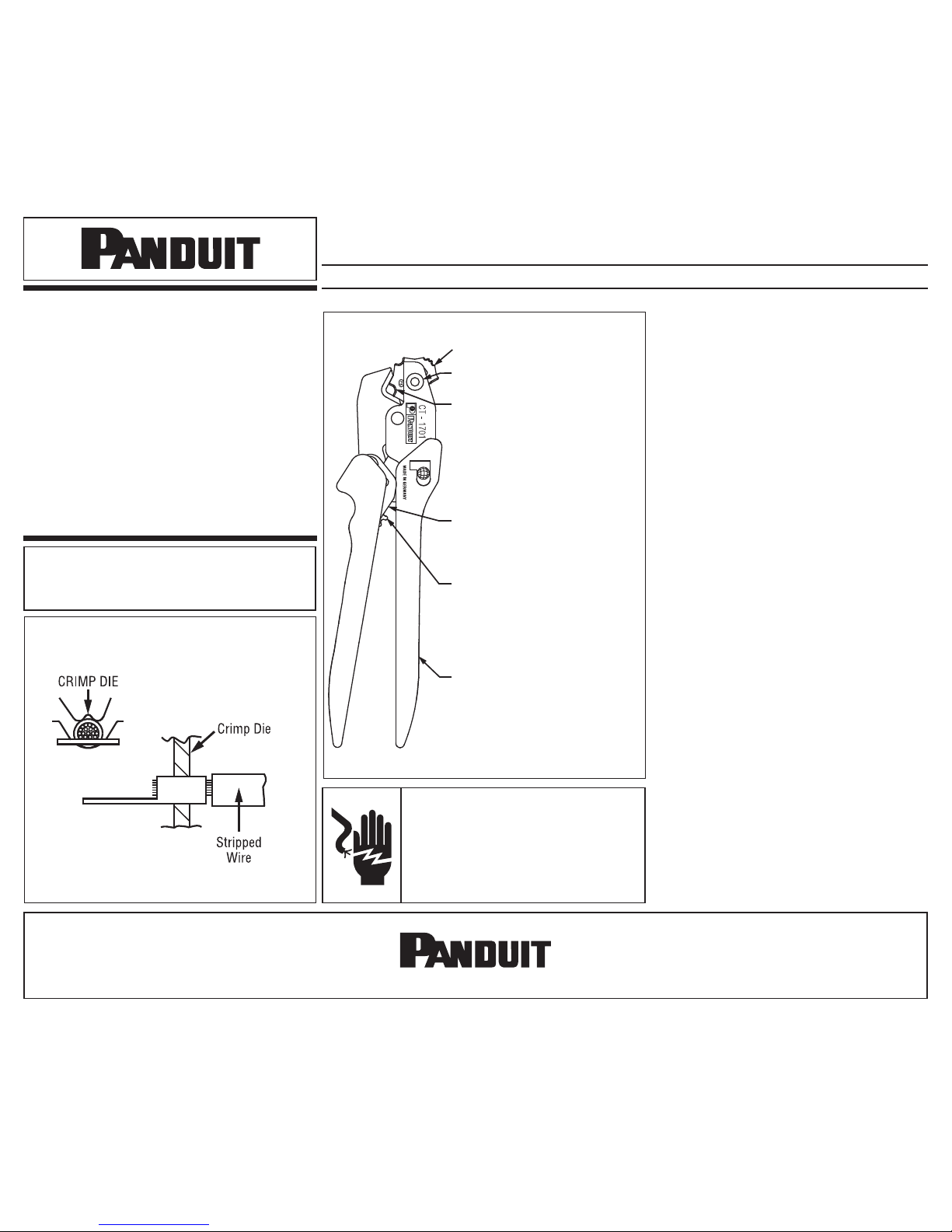
Figure 1
CRIMP POCKETS FO R
Panduit®Compression
Connectors.
Refer to product packaging fo r
wire r an ge and pr op er crimp
pocket. Crimp po ck ets ar e
identified w it h applicable die
index nu mb er.
Cushioned Ha nd le Grips
Manual r el ea se lever, pu sh
forward in the ev en t that
controlled c yc le mechanism
must b e released.
Controlled c yc le mechanism
prevents t ool fr om opening
before c ri mp cycle is complet e.
© Panduit Corp. 2011
Website: www.panduit.com
Email: cs@panduit.com
EU Website: www.panduit.com/emea
EU Email: emeatoolservicecenter@panduit.com
Panduit Corp. • USA Technical Support
Tel: 888-506-5400, ext. 3255 • Fax: 630-759-7532
Panduit Europe • EMEA Service Center
Tel: +31 546 580 452 • Fax: +31 546 580 441
CAUTION: Verify power is “OFF” before
working on wiring with this tool. The
cushioned grips are for the user’s comfort,
and are not intended to insulate against
shock while working on live
electrical circuits.
CT-1701: PA23829A01_03 Page: 1 of 2 1-2011
Rotating Crimp Die Wheel
Crimp Die Release Push Button
Figure 2
Page 2

INSPECTION/MAINTENANCE
VISUAL INSPECTION
1. Visually inspect the tool for missing or loose
pins, then close the tool and note the return
action of the handles.
2. Inspect the crimping dies for worn, chipped
or broken edges.
3. If parts are missing, defective or damaged,
contact your local Panduit Sales Office for
information on repair or replacement of tools.
DIE CLOSURE INSPECTION
Die closure is measured by using GO/NO GO
gage members (dimensions listed in Table 1).
1. Clean the crimping dies and gage member surfaces.
2. Close the tool handles until the crimping dies are bottomed and the controlled cycle mechanism
releases. Keep the handles closed together.
3. Using the appropriate gage member, attempt to insert the NO GO gage into the die opening. The NO
GO side may partially enter the die closure but must NOT pass completely through. Perform this test
for all three crimp pockets.
4. Repeat Step 3 with the appropriate GO gage for all three crimp pockets. The GO side must enter
and pass completely through the die closures.
5. If both gage conditions are met, the tool is dimensionally correct. If either condition fails, contact
Panduit Tool Division Tool Service, or Panduit EMEA Service Center for technical assistance.
PRELOAD FORCE INSPECTION
1. Close the handles until the controlled cycle
mechanism is engaged, but before the
mechanism releases.
2. Apply a force to the handles 1-1/4" (32 mm)
from the end of the handles, until the
controlled cycle release mechanism
releases. Record the reading using a force
gauge.
3. The force required to release the controlled
cycle release mechanism should be a
minimum of 15 pounds-force (67 N). If the
force required is less than 15 pounds-force
(67 N), contact Panduit Tool Division Tool
Service, or Panduit EMEA Service Center for
technical assistance.
Table 1
CT-1701 OPERATION INSTRUCTIONS
NEW TOOLS BEFORE PLACING INTO SERVICE:
All Panduit crimping tools are calibrated and inspected before they are
shipped from the factory. All new tools should be inspected before being
used.
New tools are shipped, factory lubricated, in protective packaging. After
inspection, simply clean any excess oil from the crimping dies and place into
service.
When the tool is not in use, keep the handles closed to prevent objects from
becoming lodged in the crimping area. Store the tool in a clean, dry area.
IN-SERVICE TOOLS AFTER TOOLS HAVE BEEN IN SERVICE:
It is recommended that each operator of the tool be made aware of-and
responsible for following these maintenance steps.:
In-service tools should be cleaned and inspected at least ONCE A MONTH.
To clean-wipe with a clean cloth.
In-service tools should be lubricated ONCE A WEEK, and after every
cleaning. Lubricate all pins, pivots and bearing surfaces with DOW
CORNING®Molykote BR2 Plus. Do not use oil excessively.
Be sure to clean any excess oil from the crimping dies before using.
® Molykote BR2 Plus is the Registered Trademark
of DOW CORNING
DIE CLOSURE GO / NO GO GAGE MEMBERS - TOOL NO. CT-1701
DIE INDEX
NUMBER
ENGLISH GO / NO GO GAGE MEMBERS METRIC GO / NO GO GAGE MEMBERS
“G” Dia. (GO) “NG” Dia. (NO GO) “G” Dia. (GO) “NG” Dia. (NO GO)
P10 0.099” 0.109” 2,51 mm 2,76 mm
P8 0.179” 0.201” 4,54 mm 5,10 mm
P6 0.217” 0.238” 5,51 mm 6,04 mm
P4 0.273” 0.295” 6,93 mm 7,49 mm
P2 0.351” 0.374” 8,91 mm 9,49 mm
CT-1701: PA23829A01_03 Page: 2 of 2 1-2011
TROUBLESHOOTING
 Loading...