

Page 1
Mini-Com Mini-Jack Jack Modules
R2
T2
T3
T1
R1
R3
R4
T4
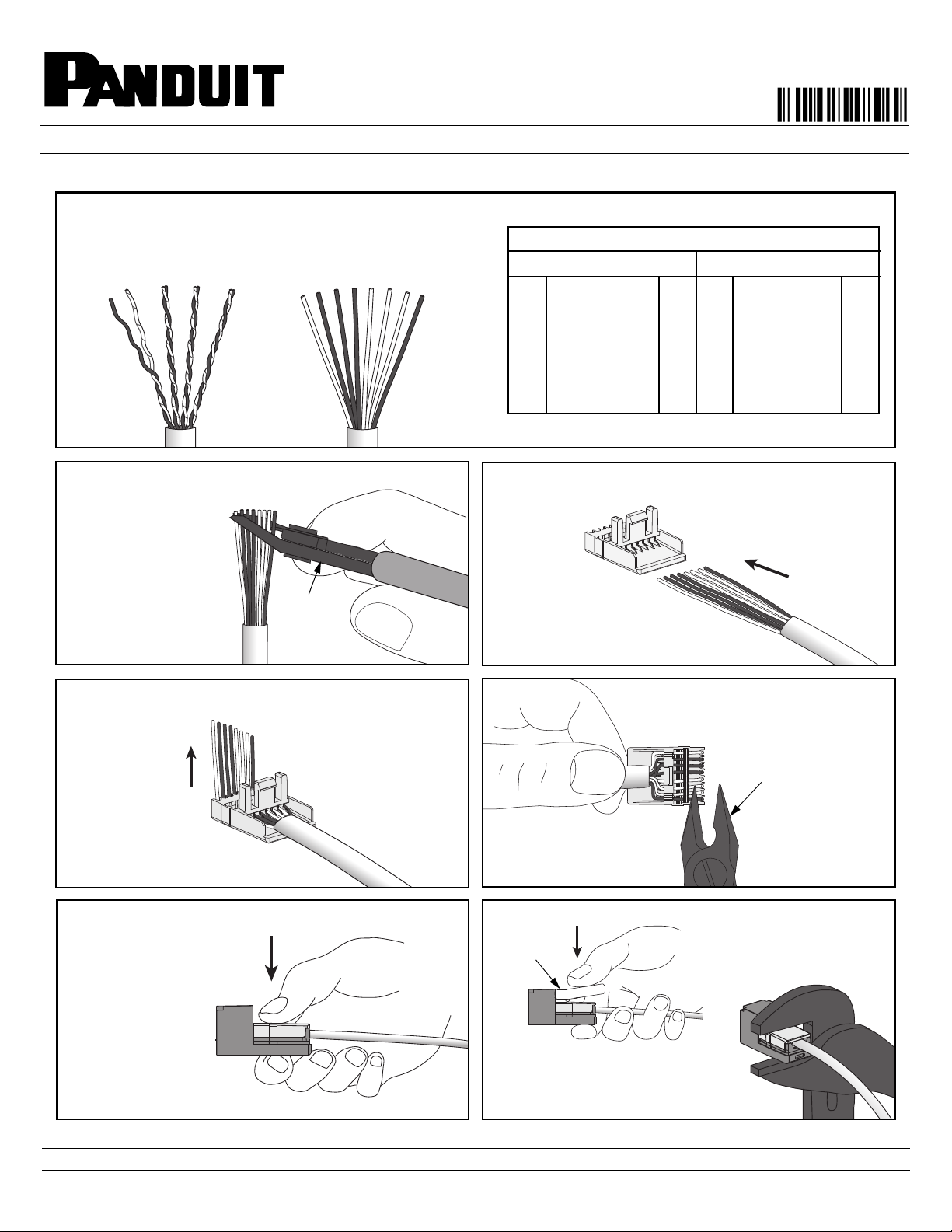
Remove all but one twist per pair, smooth conductors and
arrange in proper color sequence.
1
2
1
3
5
4
6
8
7
GREEN
WHITE/GREEN
WHITE/ORANGE
WHITE/BLUE
BLUE
ORANGE
BROWN
WHITE/BROWN
R3
T3
T2
T1
R1
R2
R4
T4
2
1
3
5
4
6
8
7
ORANGE
WHITE/ORANGE
WHITE/GREEN
WHITE/BLUE
BLUE
GREEN
BROWN
WHITE/BROWN
Mini-Com Mini-Jack Color-Coded Wire Positions
T568A T568B
7
8
6
45
3
1
2
Part Numbers - CJ588**Y, CJ5E88**Y, CJD588**Y
See Page 2 for CJ64/66/88 Series Wiring Sequences
3
4
5
CWST
6
CJT
SNAP
TOOL
7
(OR)
2
CWST
Snipping
Tool
Part Numbers: CJ588**Y, CJ5E88**Y, CJD588**Y, CJ64**Y,
CJ66**Y, CJ88**Y
© Panduit Corp. 2011
INSTALLATION INSTRUCTIONS
TERMINATION
PN45H
** Denotes color.
For Technical Support: www.panduit.com/resources/install_maintain.asp
Page 1 of 2
Page 2
© Panduit Corp. 2011
1
2
1
2
3
4
5
6
2
3
4
5
1
2
3
4
5
6
1
2
3
4
5
6
1
2
3
4
5
6
1
2
3
4
5
6
7
7
8
8
18
1
2
3
4
5
6
2
1
3
5
4
6
7
8
8
7
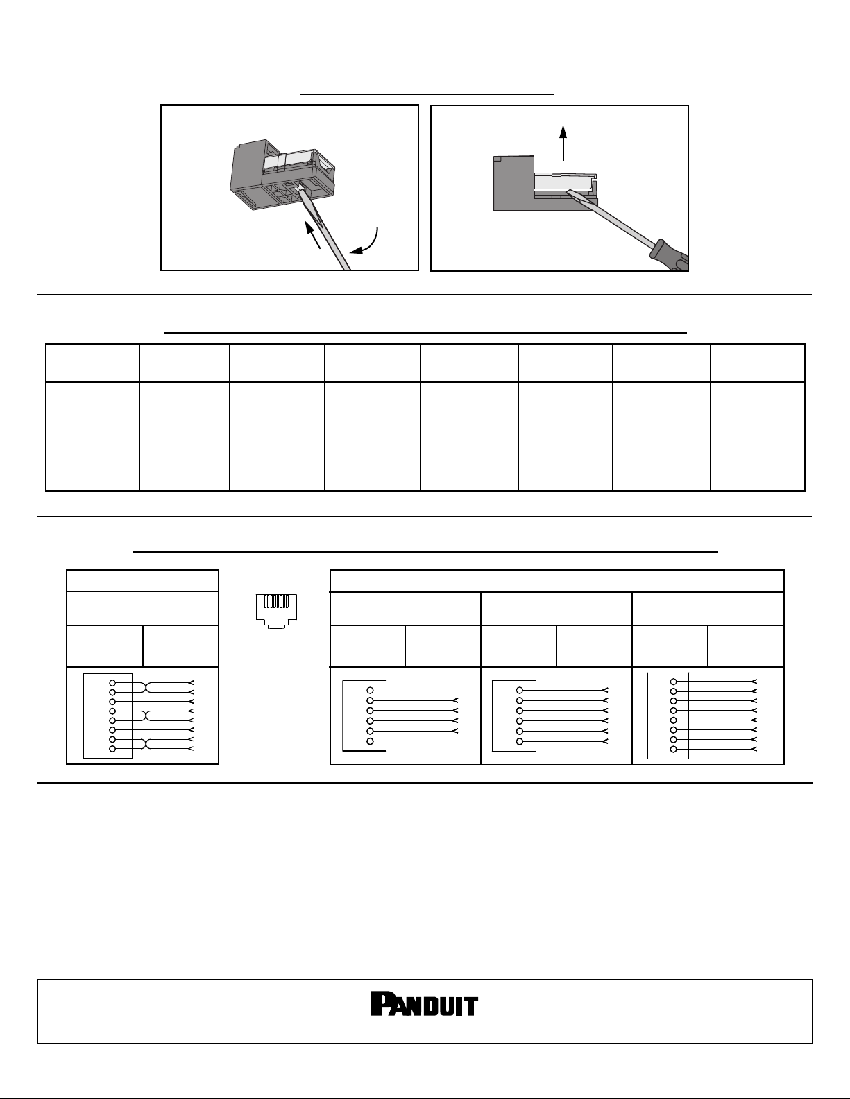
INSTALLATION INSTRUCTIONS
TERMINATION CAP REMOVAL
CATEGORY 3 Mini-Jack CJ64/66/88 SERIES WIRING SEQUENCES
PN45H
10 Base-T
WHT/GRN
1
2
WHT/BRN
3
4
5
6
7
8
GRN
BRN
NC
NC
NC
NC
T3
R3
T4
NC
NC
R4
NC
NC
WIRING DIAGRAM
Part Numbers
CJ588, CJ5E88, CJD588
Modular Plug
Contacts
EIA/TIA 568A,
ISDN
WHT/GRN
1
GRN
2
WHT/ORG
3
BLU
4
WHT/BLU
5
ORG
6
WHT/BRN
7
BRN
8
T3
R3
T2
R1
T1
R2
T4
R4
1
2
3
4
5
6
7
8
USOC 4-Wire
(8 Pin Jack)
NC
NC
WHT/ORG
BLU
WHT/BLU
ORG
NC
NC
NC
NC
T2
R1
T1
R2
NC
NC
RJ45, USOC
8-Wire
BRN
1
WHT/GRN
2
WHT/ORG
3
BLU
4
WHT/BLU
5
ORG
6
GRN
7
WHT/BRN
8
R4
T3
T2
R1
T1
R2
R3
T4
EIA/TIA 568B,
AT&T 258A,
WECO
WHT/ORG
1
ORG
2
WHT/GRN
3
BLU
4
WHT/BLU
5
GRN
6
WHT/BRN
7
BRN
8
T2
R2
T3
R1
T1
R3
T4
R4
1
2
3
4
5
6
USOC 4-Wire,
in 6 pin
WHT/ORG
BLU
WHT/BLU
ORG
T2
R1
T1
R2
USOC 6-Wire
(8 Pin Jack)
NC
1
WHT/GRN
2
WHT/ORG
3
BLU
4
WHT/BLU
5
ORG
6
GRN
7
NC
8
WIRING DIAGRAMS FOR CJ588, CJ5E88, CJD588, CJ64/66/88 SERIES
Insulation
Displacement
Contacts
Pin #’s
Part Number Part Number
CJ64 CJ66
Modular Plug
Contacts
Insulation
Displacement
Contacts
WIRING DIAGRAM
Modular Plug
Contacts
Insulation
Displacement
Contacts
Par t Number
Modular Plug
Contacts
NC
1
T3
2
T2
3
R1
4
T1
5
R2
6
R3
NC
CJ88
Insulation
Displacement
Contacts
USOC,
RJ11/RJ25
WHT/GRN
WHT/ORG
BLU
WHT/BLU
ORG
GRN
T3
T2
R1
T1
R2
R3
Notes:
1. For specified performance, follow TIA/EIA 568-B installation guidelines.
2. Jack Modules can terminate PVC or Plenum rated 22-24 AWG solid or stranded IWC cable with insulated conductor
outside diameter ranging between 0.035 inch (0.88mm) and 0.048 inch (1.2mm).
3. Jack Modules may be re-terminated a minimum of 10 times.
4. For technical and performance information, consult Panduit Technical Support.
5. MUAJC588 Jack Modules suit a standard switch mechanism pattern on various Australian faceplates.
6. For Mini-Com Mini-Jack Shielded Jack Module instructions, refer to PN348*.
As with all Wiring Accessories, the following statements apply:
1. Never install communications wiring during a lightning storm.
2. Never install communications wiring in wet locations unless the jack is specifically designed for use in wet locations.
3. Never touch uninsulated communications wiring or terminals unless the communication line has been disconnected
at the network interface.
4. Use caution when installing or modifying communication wiring.
For Instructions in Local Languages
and Technical Support:
www.panduit.com/resources/install_maintain.asp
www.panduit.com
Page 2 of 2
E-mail:
cs@panduit.com
Fax:
(708) 444-6993
 Loading...