

Page 1

INSTALLATION GUIDE
Hub-to-G5 iPDU
Patch Cord (3m length)
ACE01:
Card Reader
for Hot Aisle, use ACB05
for Cold Aisle, use ACB04
ACB01:
Access Hub
ACE02 or ACE03:
with Card Reader
ACE01:
without Card Reader
Access Hub
Harness
Rack Access Security
Electronic Swinghandle
Rack Access Security provides robust cabinet access control by managing user authentication and authorization, event
recording, and alarming/notification when used with a G5 iPDU. The Access Hub has an integrated Door Switch
Sensor and provides an additional sensor-port connection for other environmental or access control accessories.
Rack Access Security has been designed specifically to integrate into Panduit Net-Access cabinets but may also be
integrated into a wide range of alternative cabinets during deployment or as retrofit enhancements. For each handle
type, all four parts in this system (a Swinghandle, a Harness, an Access Hub, and a Hub-to-G5 iPDU Patch Cord) must
be ordered to secure one door. The part numbers are shown in the table below. It is recommended to use the Door
Brackets (sold separately) for mounting the Access Hub’s magnetic switch and magnet in Panduit cabinet
deployments. Installation of the
disconnect coupler and standard ethernet cable (sold separately) that allows for the
Hub, movement of equipment, and an easy
work on single-cam doors only.
The following table shows the required part numbers for each type of access installation bas ed on the S wing hand le
type.
Electronic Swinghandle
sensors and ongoing equipment maintenance is further facilitated by using a quick
convenient positioning of Access
disconnect method for removing cabinet doors. NOTE: The Swinghandles
Electronic Swinghandles Harnesses Access Hub
Electronic Swinghandle without
Electronic Swinghandle wit h Low
Frequency (125kHz) Card Reader
Electronic Swinghandle with High
Frequency (13.56MHz) Card Reader
Customer Service: CS@panduit.com 800.777.3300 Technical Support: techsupport@panduit.com 866.405.6654 page 1
ACE02:
ACE03:
for Hot Aisle, use ACB03
for Cold Aisle, use ACB02
for Hot Aisle, use ACB03
for Cold Aisle, use ACB02
ACB01 UTP28CH3MBL
IM034 Rev 02
Page 2
INSTALLATION GUIDE
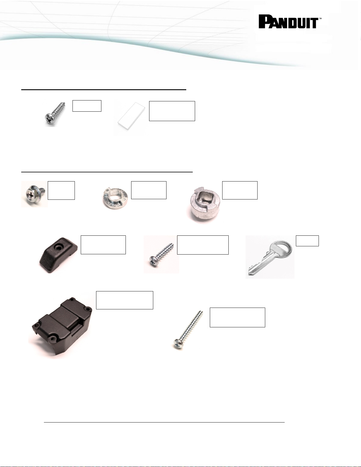
Screws
Double-Sided
Cam
Screw
Standard
Stop Disc
Extended
Stop Disc
Top Mounting
Bracket
Bottom Mounting
Bracket
Top Mounting
Screw (14mm)
Screws (25mm)
Keys
ACCESS HUB INCLUDED IN STAL LATION PART S
Tape
SWINGHANDLE INCLUDED INSTALLATION PARTS
Bottom Mounting
Customer Service: CS@panduit.com 800.777.3300 Technical Support: techsupport@panduit.com 866.405.6654 page 2
IM034 Rev 02
Page 3
INSTALLATION GUIDE
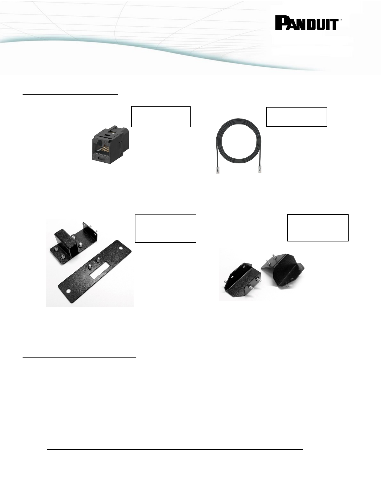
Quick Disconnect
Standard Ethernet
Cable (2m)
Panduit Full-Door
Magnetic Sensors
Panduit Split-Door
Magnetic Sensors
OPTIONAL ACCESSORIES
Coupler
Panduit PN: CC5E88BL Panduit PN: UTP28CH2MBL
Panduit PN: MA015 Panduit PN: MA016
Mounting Kit for
Mounting Kit for
INSTALLATION INSTRUCTIONS
The Access Hub and Harness come with different cable lengths to enable each item to be mounted in either the
Hot or Cold Aisle locations.
NOTE: The remainder of this guide demonstrates installation into a Panduit cabinet. Pay careful attention to the
part numbers and location of each item. Adaptation to the installation locations/method may be required for other
cabinets. It is also assumed that the G5 iPDU is located at the rear of the cabinet.
Customer Service: CS@panduit.com 800.777.3300 Technical Support: techsupport@panduit.com 866.405.6654 page 3
IM034 Rev 02
Page 4

INSTALLATION GUIDE
Aisle Setting
Access Hub Mounting
1. Set the switch on the Access Hub to Cold Aisle for the front door and Hot Aisle for the rear door.
NOTE: For ease of installation of the Access Hub’s magnetic switch and magnet in Pan du it cabinets, use FullDoor Sensor Bracket Kit (Panduit PN: MA015) or Split-Door Sensor Bracket Kit (Panduit PN: MA016). Installation
instructions and hardware are included with the bracket kits.
1. Attach the Access Hub’s magnet to the top corner of the cabinet using the inc l ud ed double-sided tape, screws,
or optional bracket hardware (if applicable). See Figure 1.
Switch
2. Attach the Access Hub’s magnetic switch to the top corner of the cabinet door opposite the magnet using
double-sided tape, screws, or bracket hardware (if applicable). See Figure 1. Route and secure the cable to
the cabinet door using adhesive backed mount and cable ties as needed.
NOTE: The operating distance between the Magnetic Switch and the Magnet is dependent on the installation. In a
typical installation the distance between the Magnetic Switch and Magnet should be less than 10mm when the
cabinet door is in the closed position. Greater distances may cause the G5 iPDU to read the door as “OPEN”.
Figure 1: Access Hub's Magnetic Switch and Magnet Placement
Customer Service: CS@panduit.com 800.777.3300 Technical Support: techsupport@panduit.com 866.405.6654 page 4
IM034 Rev 02
Page 5

INSTALLATION GUIDE
Swinghandle Lock Mounting Option for Front and Rear Door
1. If needed, remove any existing lock mechanism. Save the Cam (latch) for later steps.
NOTE: The Swinghandle’s lock requires a cut-out of 150x25mm. Reference Figure 2 for the following steps. Use a
#1 POZIDRIV driver when securing the mounting screws for Top and Bottom Mounting Brackets.
2. Position the lock body within the cut-out and flush to the outer face of the cabin et door . Use the 14mm Top
Mounting Screw and Top Mounting Bracket to secure the lock to the door.
3. Select a suitable Stop Disc (standard or extended) and mount the cam assembly from Step 1. Secure using the
included Cam Screw. Pay careful attention to the orientation of the Stop Disc according to your installation
requirements.
Figure 2: Swinghandle Inst allat ion onto Cabinet Door
4. Ensure that the orientation of the lock plug corresponds to the orientation of the Bottom Mounting Bracket and
install the Bracket using the included 25mm Bottom Mounting Screws.
Customer Service: CS@panduit.com 800.777.3300 Technical Support: techsupport@panduit.com 866.405.6654 page 5
IM034 Rev 02
Page 6

INSTALLATION GUIDE
Wire Harness Connection
1. Connect the Swinghandle to the Access Hub with the appropriate Harness. Reference the connection diagram
shown in Figure 3 for standard applications. Figure 4 shows connections if extra length or convenience is
required from the G5 iPDU to the Access Hub.
2. Connect any environmental or access control accessory to port marked “Sensor” on the Access Hub. Ask yo ur
local representative for more details.
3. Access the G5 iPDU Web Interface to manage the Access Security configuration alarms and notification settings.
Figure 3: Connection Diagram of Rack Access Control Security
Figure 4: Connection Diagram of Rack Access Control Security with Extension
4. Rack Access Security is now installed and ready to use.
Customer Service: CS@panduit.com 800.777.3300 Technical Support: techsupport@panduit.com 866.405.6654 page 6
IM034 Rev 02
 Loading...