

PANCONTROL PAN IR-T650 User Manual
MANUAL
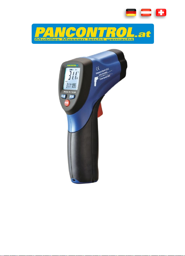
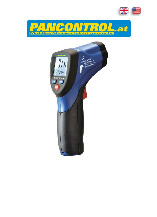
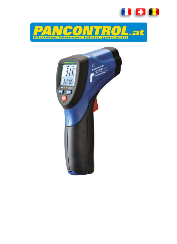
PAN IR-T650

INDEX
Deutsch
DE 1 - DE 11
English
EN 1 - EN 11
Français
FR 1 - FR 11
Italiano
IT 1 - IT 11
Espaniol
ES 1 - ES 11
Nederlands
NL 1 - NL 11
Svenska
SE 1 - SE 11
Čeština
CZ 1 - CZ 11
Slovensky
SK 1 - SK 11
Magyar
HU 1 - HU 11
Slovensko
SI 1 - SI 11
Hrvatski
HR 1 - HR 11
Polski
PL 1 - PL 11
Български
BG 1 - BG 11
Română
RO 1 - RO 11
Русский
RU 1 - RU 11
Bedienungsanleitung
PAN IR-T650
Infrarotthermometer

DE 2
INHALT
1. Einleitung ................................................................................................2
2. Lieferumfang...........................................................................................3
3. Allgemeine Sicherheitshinweise .............................................................3
4. Erläuterungen der Symbole am Gerät.....................................................4
5. Bedienelemente .....................................................................................4
6. Das Display und seine Symbole ...............................................................5
7. Technische Daten....................................................................................6
8. Bedienung ...............................................................................................7
9. Instandhaltung ...................................................................................... 10
10. Gewährleistung und Ersatzteile ............................................................ 11
1. Einleitung
Vielen Dank, dass Sie sich für ein PANCONTROL Gerät entschieden haben. Die
Marke PANCONTROL steht seit über 20 Jahren für praktische, preiswerte und
professionelle Messgeräte. Wir wünschen Ihnen viel Freude mit Ihrem neuen
Gerät und sind überzeugt, dass es Ihnen viele Jahre gute Dienste leisten wird.
Bitte lesen Sie diese Bedienungsanleitung vor der ersten Inbetriebnahme des
Gerätes zur Gänze aufmerksam durch, um sich mit der richtigen Bedienung des
Gerätes vertraut zu machen und Fehlbedienungen zu verhindern. Befolgen Sie
insbesondere alle Sicherheitshinweise. Eine Nichtbeachtung kann zu Schäden
am Gerät, und zu gesundheitlichen Schäden führen.
Verwahren Sie diese Bedienungsanleitung sorgfältig, um später nachschlagen
oder sie mit dem Gerät weitegergeben zu können.

DE 3
2. Lieferumfang
Bitte überprüfen Sie nach dem Auspacken den Lieferumfang auf
Transportbeschädigungen und Vollständigkeit.
Messgerät
Batterie(n)
Gepolsterte Tragtasche
Bedienungsanleitung
3. Allgemeine Sicherheitshinweise
Um eine sichere Benutzung des Gerätes zu gewährleisten, befolgen Sie bitte
alle Sicherheits- und Bedienungshinweise in dieser Anleitung.
- Das Gerät darf nicht mehr benutzt werden, wenn das Gehäuse beschädigt
ist, wenn eine oder mehrere Funktionen ausfallen, wenn keine Funktion
angezeigt wird oder wenn Sie vermuten, dass etwas nicht in Ordnung ist.
- Wenn die Sicherheit des Anwenders nicht garantiert werden kann, muss
das Gerät außer Betrieb genommen und gegen Verwendung geschützt
werden.
- Schützen Sie Ihre Augen! Richten Sie den Laser nie in das Gesicht von
Personen oder Tieren.
- Wenn das Batteriesymbol in der Anzeige erscheint, erneuern Sie bitte
sofort die Batterie.
- Lagern Sie das Gerät nicht in direkter Sonnenbestrahlung.
- Wenn Sie das Gerät längere Zeit nicht benutzen, entfernen Sie die
Batterie.
- Wenn das Gerät modifiziert oder verändert wird, ist die Betriebssicherheit
nicht länger gewährleistet. Zudem erlöschen sämtliche Garantie- und
Gewährleistungsansprüche.
DE 4
Übereinstimmung mit der EU-Niederspannungsrichtlinie (EN-61010)
Schutzisolierung: Alle spannungsführenden Teile sind doppelt isoliert
Gefahr! Beachten Sie die Hinweise der Bedienungsanleitung!
Achtung! Gefährliche Spannung! Gefahr von Stromschlag.
Dieses Produkt darf am Ende seiner Lebensdauer nicht in den
normalen Haushaltsabfall entsorgt werden, sondern muss an einer
Sammelstelle für das Recycling von elektrischen und elektronischen
Geräten abgegeben werden.
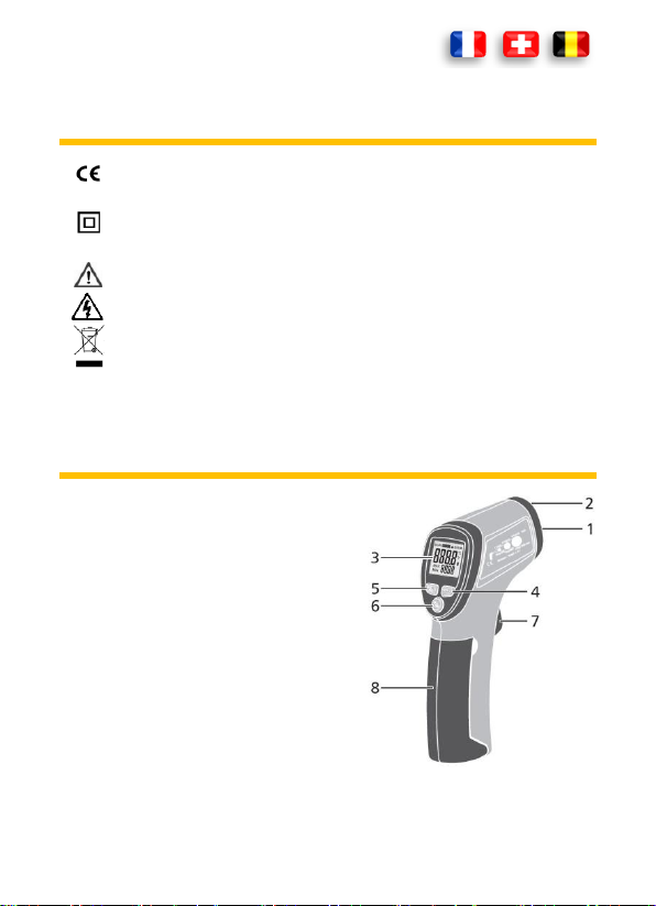
4. Erläuterungen der Symbole am Gerät
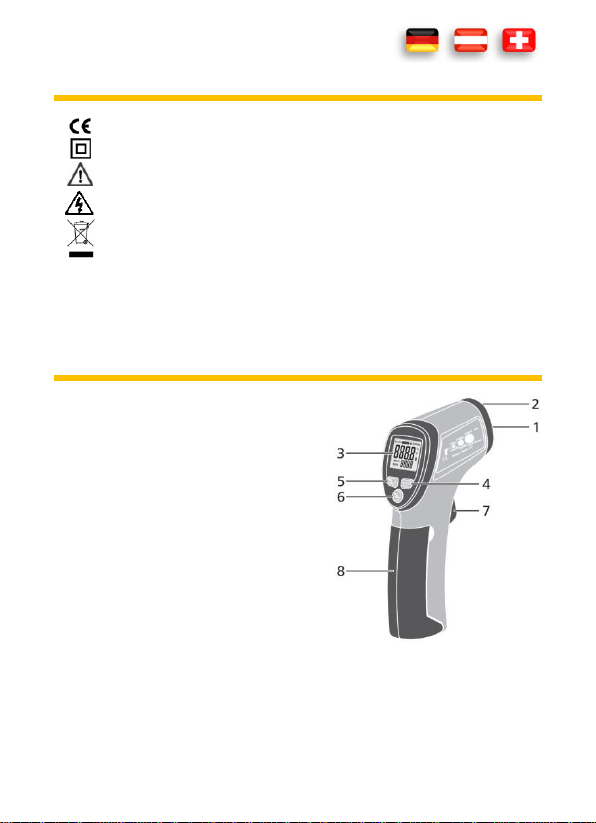
5. Bedienelemente
1. IR -Sensor
2. LASER
3. Anzeige
4. DOWN-Taste /
Hintergrundbeleuchtung
5. UP-Taste / Laser
6. MODE-Taste
7. Messtaste (Abzug)
8. Batteriefach
Der °C/°F Umschalter befindet sich hinter dem Batteriefach.
DE 5
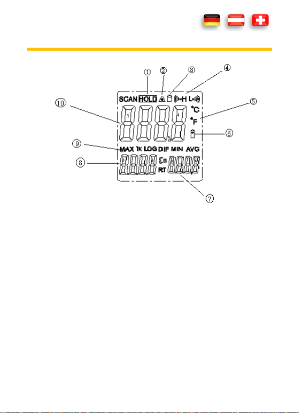
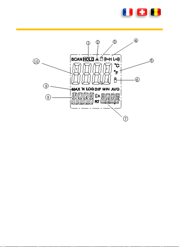
6. Das Display und seine Symbole
1. Hold, Anzeigewert halten
2. LASER
3. LOCK Funktion
4. ALARM Niedrigster / höchster Wert
5. Temperatur in Celsius oder Fahrenheit
6. Batterie schwach
7. Emissionsgrad
8. MIN/MAX Anzeige
9. MIN//MAX Symbol
10. Anzeige
DE 6
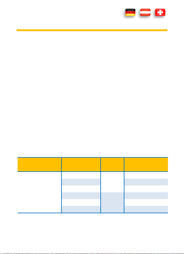
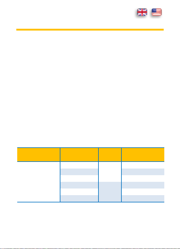
7. Technische Daten
Anzeige
4 - Stellen LCD (bis 9999),
Hintergrundbeleuchtung
Laser
Überlastanzeige
Class II (1mW / 630-670 nm)
----
Messrate
6,5x / s
Emissionsgrad
Der Emissionsgrad ist von 0,10 bis 1,0
einstellbar.
Ansprechzeit
< 150 ms
Optische Auflösung
12:1
Stromversorgung
1 x 9 V (NEDA 1604) Batterie(n)
Automatische
Abschaltung
8 s
Betriebsbedingungen
0º C bis 50º C / < 90% Relative Luftfeuchte
Lagerbedingungen
-10º C bis 60º C / < 80% Relative Luftfeuchte
Gewicht
163 g
Abmessungen
146 x 104 x 43 mm
Funktion
Bereich
Auflösung
Genauigkeit in % vom
angezeigten Wert
Temperaturmessung
(°C/°F)
-50°C bis 20°C
0,1 °C
(2,5°C)
20°C bis 300°C
(1% 1°C)
300°C bis 650°C
(1,5%)
-58°F bis 68°F
0,1 °F
(4,5°F)
68°F bis 572°F
(1% 1,8°F)
572°F bis 1202°F
(1,5%)
DE 7
8. Bedienung
Infrarot Thermometer messen nur die Oberflächentemperatur eines Objektes.
Das Gerät kann nicht durch transparente Oberflächen wie Glas messen. Es
würde die Temperatur der Glasoberfläche messen. Um dies zu kompensieren,
bekleben Sie die Oberfläche mit schwarzem Klebeband. Geben Sie dem
Klebeband etwas Zeit um die Temperatur des Messobjektes anzunehmen und
messen Sie dann die Temperatur des Klebebandes. Eine Verschmutzte
Messoptik (z.b. durch Rauch, Staub oder Dampf) beeinträchtigen eine genaue
Messung.
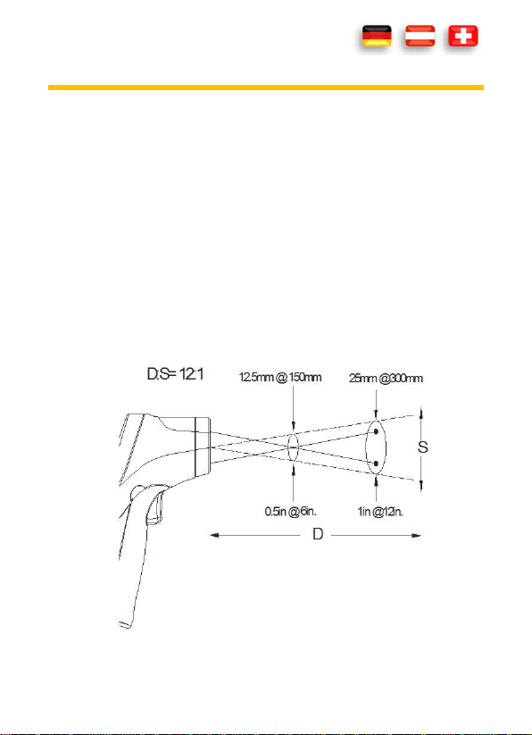
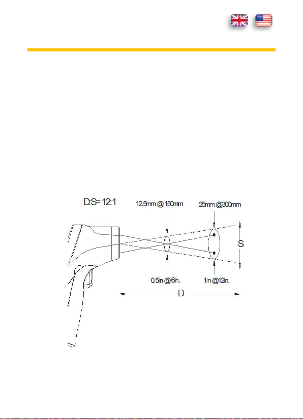
Wenn der Abstand zwischen Messgerät und Messobjekt zunimmt, wird auch
die gemessen Fläche entsprechend größer. Das Verhältnis zwischen Abstand
und Messfläche sehen Sie in der Graphik unten.
DE 8
Stellen Sie sicher, daß die zu messende Fläche des Messobjekts größer als der
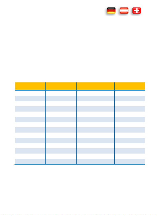
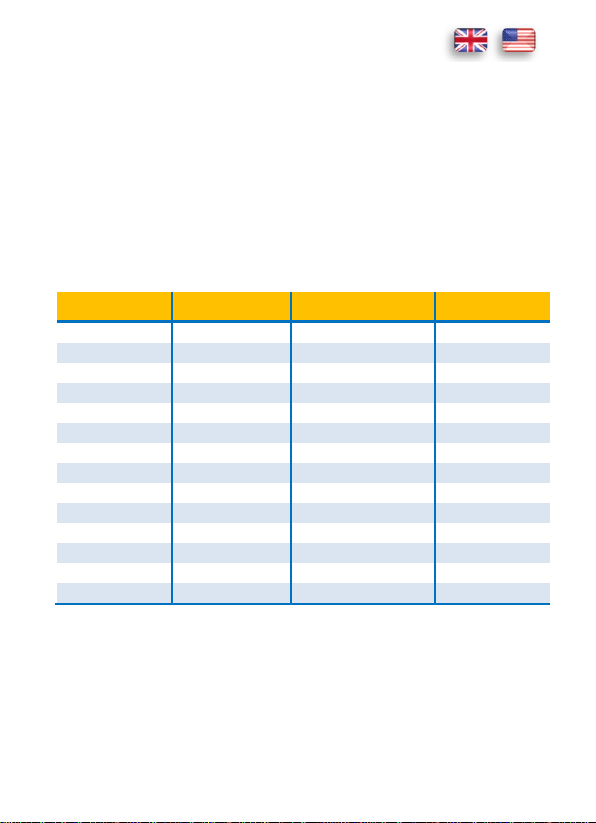
Material
Emissionsgrad
Material
Emissionsgrad
Asphalt
0.90 to 0.98
Kleidung (schwarz)
0.98
Beton
0.94
menschliche Haut
0.98
Zement
0.96
Leder
0.75 to 0.80
Sand
0.90
Holzkohle
0.96
Erde
0.92 to 0.96
Lack
0.80 to 0.95
Wasser
0.92 to 0.96
Lack (matt)
0.97
Eis
0.96 to 0.98
Gummi (schwarz)
0.94
Schnee
0.83
Kunststoff
0.85 to 0.95
Glas
0.90 to 0.95
Holz
0.90
Keramik
0.90 to 0.94
Papier
0.70 to 0.94
Marmor
0.94
Chromoxyd
0.81
Gips
0.80 to 0.90
Kupferoxyd
0.78
Mörtel
0.89 to 0.91
Eisenoxyd
0.78 to 0.82
Ziegel
0.93 to 0.96
Textilien
0.90
Messpunkt ist. Je kleiner das Messobjekt ist, umso kleiner muß der Abstand
zum Messgerät sein. Um eine genaue Messung zu erhalten, sollte das
Messobjekt mindestens doppelt so groß sein wie der Messpunkt.
Emissionsgrad
Der Emissionsgrad beschreibt die Energie emittierenden Eigenschaften von
Materialien. Die meisten (90%) der organische Materialien haben einen
Emissionsgrad von 0,95 (im Gerät voreingestellt). Der Emissionsgrad ist von
0,10 bis 1,0 einstellbar.
DE 9
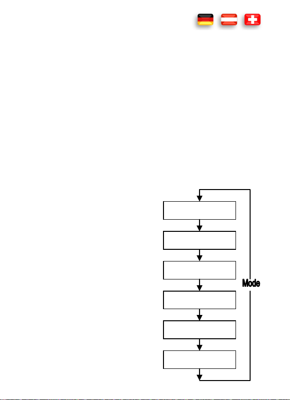
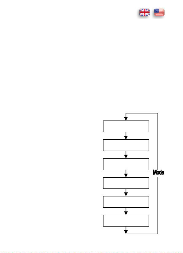
LOCK on/off
HAL on/off
HAL adjustment
LOW on/off
LOW adjustment
EMS adjustment
Temperaturmessung °C/°F
1. Halten Sie das Messgerät am Griff und zielen Sie auf das Messobjekt.
2. Um das Gerät einzuschalten und den Messvorgang zu beginnen drücken
Sie die Messtaste (Abzug).
3. Wenn die Batterie nicht erschöpft ist, schaltet sich die Anzeige ein und
zeigt den Messwert an. Falls nicht, wechseln Sie bitte die Batterie.
4. Wenn Sie die Messtaste (Abzug) loslassen, erscheint HOLD in der Anzeige.
5. Drücken Sie die UP - Taste um den LASER ein- bzw. auszuschalten oder
die DOWN - Taste um die Hintergrundbeleuchtung ein- bzw. auszuschlten.
6. Das Messgerät schaltet sich automatisch nach 7 Sekunden aus, wenn
nicht die LOCK-Funktion eingeschaltet ist.
Das Messgerät kompensiert automatisch die Umgebungstemperatur. Bei
großen Temperaturdifferenzen, kann das bis zu 30 Minuten in Anspruch
nehmen.
MODE Funktion
Drücken Sie die MODE-Taste um die
gewünschte Funktion auszuwählen.
Durch mehrmaliges Drücken der MODE
Taste können Sie die Einstellungen für
EMS, LOCK ON/OFF, HAL ON/OFF und
LOW ändern. Das Flussdiagramm zeigt die
entsprechende Reihenfolge.
EMS Funktion
Der Emissionsgrad beschreibt die Energie
emittierenden Eigenschaften von
Materialien. Der Emissionsgrad ist von
0,10 bis 1,0 einstellbar.

DE 10
LOCK Funktion
Die LOCK Funktion ermöglicht ununterbrochene Temperaturmessung. Um sie
ein-, bzw. auszuschalten drücken Sie die UP-Taste. Zur Bestätigung der
Änderung drücken Sie die Messtaste (Abzug).
HAL Funktion
Die HAL Funktion ermöglicht die Einstellung des Minimum- und
Maximumalarms. Um sie Ein-, bzw. Auszuschalten drücken Sie die UP oder
DOWN Taste. Zur Bestätigung der Änderung drücken Sie die Messtaste
(Abzug).
9. Instandhaltung
Reparaturen an diesem Gerät dürfen nur von qualifizierten Fachleuten
ausgeführt werden.
Hinweis: Bei Fehlfunktionen des Messgeräts prüfen Sie:
- Funktion und Polarität der Batterie
- Funktion der Sicherungen (falls vorhanden)
Austauschen der Batterie(n)
Sobald das Batteriesymbol oder BATT am Display erscheint, ersetzen Sie die
Batterie.
1. Klappen Sie das Batteriefach auf.
2. Setzen Sie die Batterie in die Halterung ein und beachten Sie die richtige
Polarität.
3. Schließen Sie das Batteriefach.
4. Entsorgen Sie leere Batterien umweltgerecht.
DE 11
5. Wenn Sie das Gerät längere Zeit nicht benutzen, entfernen Sie die
Batterie.
Reinigung
Bei Verschmutzung reinigen Sie das Gerät mit einem feuchten Tuch und etwas
Haushaltsreiniger. Achten Sie darauf, dass keine Flüssigkeit in das Gerät dringt!
Keine aggresiven Reinigungs- oder Lösungsmittel verwenden!
10. Gewährleistung und Ersatzteile
Für dieses Gerät gilt die gesetzliche Gewährleistung von 2 Jahren ab
Kaufdatum (lt. Kaufbeleg). Reparaturen an diesem Gerät dürfen nur durch
entsprechend geschultes Fachpersonal durchgeführt werden. Bei Bedarf an
Ersatzteilen sowie bei Fragen oder Problemen wenden Sie sich bitte an Ihren
Fachhändler oder an:
Manual
PAN IR-T650
Infrared thermometer

EN 2
CONTENTS
1. Introduction ............................................................................................2
2. Scope of delivery.....................................................................................2
3. Safety Instructions ..................................................................................3
4. Symbols Description ...............................................................................3
5. Panel Description ....................................................................................4
6. Symbols of the Display ............................................................................5
7. General Specifications ............................................................................6
8. Operating Instructions ............................................................................7
9. Maintenance ......................................................................................... 10
10. Guarantee and Spare Parts ................................................................... 11
1. Introduction
Thank you for purchasing PANCONTROL. For over 20 years the PANCONTROL
brand is synonymous with practical, economical and professional measuring
instruments. We hope you enjoy using your new product and we are
convinced that it will serve you well for many years to come.
Please read this operating manual carefully before using the device to become
familiar with the proper handling of the device and to prevent faulty
operations. Please follow all the safety instructions. Nonobservance cannot
only result in damages to the device but in the worst case can also be harmful
to health.
2. Scope of delivery
After unpacking please check the package contents for transport damage and
completeness.

EN 3
Measurement device
Conforms to the relevant European Union directive (EN-61010)
Product is protected by double insulation
Risk of Danger. Important information See instruction manual
Battery(s)
Protective cover
Manual
3. Safety Instructions
To ensure the safe use of the device, please follow all the safety and operating
instructions given in this manual.
- The device may not be used if the housing is damaged, if one or more
functions are not working, if functions are not displayed, or if you suspect
that something is not right.
- If the safety of the user cannot be guaranteed, the device may not be
operated and secured against use.
- Protect your eyes! Never direct the laser in the face of people or animals.
- If the battery symbol appears in the display, replace the battery
immediately.
- Do not store the device in places which are exposed to direct sunlight.
- Remove the battery if the device is not used for a long time.
- If changes or modifications are made to the device, the operational safety
is no longer guaranteed and the warranty becomes void.
4. Symbols Description
EN 4
Attention! Hazardous voltage. Risk of electric shock.
This product should not be disposed along with normal domestic
waste at the end of its service life but should be handed over at a
collection point for recycling electrical and electronic devices.
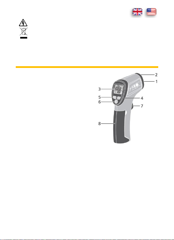
5. Panel Description
1. IR -Sensor
2. LASER
3. Display
4. DOWN-Button / Backlight
5. UP-Button / Laser
6. MODE-Button
7. Test button (trigger)
8. battery compartment
The °C / °F switch is located behind the battery compartment.
EN 5
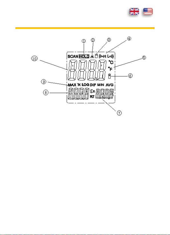
6. Symbols of the Display
1. Data hold
2. LASER
3. LOCK Function
4. ALARM MIN / MAX value
5. Temperature in Celsius or Fahrenheit
6. Battery low
7. Emissivity
8. MIN/MAX Display
9. MIN//MAX Symbol
10. Display
EN 6
7. General Specifications
Display
4 - Digits LCD (to 9999), Backlight
Laser
Overload indicator
Class II (1mW / 630-670 nm)
----
Measuring rate
6,5x / s
Emissivity
The emissivity can be adjusted from 0.10 to
1.0.
response time
< 150 ms
Optical resolution
12:1
Power supply
1 x 9 V (NEDA 1604) Battery(s)
Auto power off
8 s
Operating temperature
0º C to 50º C / < 90% Relative Humidity (%RH)
Storage temperature
-10º C to 60º C / < 80% Relative Humidity
(%RH)
Weight
163 g
Dimensions
146 x 104 x 43 mm
Function
Range
Resolution
Accuracy of the value
displayed in %
Temperature
measurement
(°C/°F)
-50°C to 20°C
0,1 °C
(2,5°C)
20°C to 300°C
(1% 1°C)
300°C to 650°C
(1,5%)
-58°F to 68°F
0,1 °F
(4,5°F)
68°F to 572°F
(1% 1,8°F)
572°F to 1202°F
(1,5%)
EN 7
8. Operating Instructions
Infrared thermometers measure the surface temperature of an object. The
device cannot measure through transparent surfaces like glass. It would
measure the temperature of the glass surface. Cover the surface using a black
adhesive tape to compensate for this. Give the adhesive tape some time to
assume the temperature of the test object and then measure the temperature
of the adhesive tape. Contaminated optics (for e.g., by smoke, dust or vapour)
affect the accuracy of the measurement.
If the distance between the measuring device and the test object increases,
the measured area becomes correspondingly larger. The relationship between
the distance and measured area can be seen in the graph below.
EN 8
Ensure that the area to be measured of the test object is larger than the
Substance
emissivity
Substance
emissivity
Asphalt
0.90 to 0.98
Cloth (black)
0.98
Concrete
0.94
Human skin
0.98
Cement
0.96
Leather
0.75 to 0.80
Sand
0.90
Charcoal (powder)
0.96
Earth
0.92 to 0.96
Lacquer
0.80 to 0.95
Water
0.92 to 0.96
Laquer (matt)
0.97
Ice
0.96 to 0.98
Rubber (black)
0.94
Snow
0.83
Plastic
0.85 to 0.95
Glass
0.90 to 0.95
Timber
0.90
Ceramic
0.90 to 0.94
Paper
0.70 to 0.94
Marble
0.94
Chromium oxides
0.81
Plaster
0.80 to 0.90
Copper oxides
0.78
Mortar
0.89 to 0.91
Iron oxides
0.78 to 0.82
Brick
0.93 to 0.96
Textiles
0.90
measuring point. The smaller the test object, the smaller must be the distance
to the measuring device. The test object should be at least twice as large as
the measuring point to get an accurate measurement.
Emissivity
The emissivity describes the energy-emitting properties of materials. Most of
the organic materials (90%) have an emissivity of 0.95 (preset in the device).
The emissivity can be adjusted from 0.10 to 1.0.
EN 9
LOCK on/off
HAL on/off
HAL adjustment
LOW on/off
LOW adjustment
EMS adjustment
Temperature measurement °C/°F
1. Hold the measuring device using the handle and point it at the test object.
2. Press the test button (trigger) to switch on the device and to start the
measurement process.
3. If the battery is not empty, the display switches on and shows the
measured value. If not, please change the battery.
4. If you release the test button (trigger), HOLD is shown in the display.
5. Press the UP - button to turn the laser on and off or the DOWN - button
to turn the background lighting on and off.
6. The meter turns off automatically after 7 seconds, when the LOCK
function is not activated.
The measuring device automatically compensates the ambient temperature.
This may take upto 30 minutes in case of large temperature differences.
MODE Function
Press the MODE button to select the
desired function.
By repeatedly pressing the MODE button,
you can change the settings for EMS, LOCK
ON / OFF, HAL ON / OFF and LOW. The
flow chart shows the corresponding
sequence.
EMS Function
The emissivity describes the
energy-emitting properties of materials.
The emissivity can be adjusted from 0.10
to 1.0.

EN 10
LOCK Function
The LOCK function enables temperature to be measured continuously. Press
the UP button to turn it on or off. Press the test button (trigger) to confirm the
change.
HAL Function
The HAL function enables the setting of the minimum and maximum alarm.
Press the UP or DOWN button to turn it on or off. Press the test button
(trigger) to confirm the change.
9. Maintenance
Only authorized service technicians may repair the instrument.
Note: If the instrument is malfunctioning, please test:
- Battery condition and polarity
- Condition of the fuse(s) if available.
Changing the battery(s)
Replace the battery(s) when the battery symbol or BATT is displayed on the
LCD.
1. Open the battery compartment.
2. Replace the battery. Mind the correct polarity.
3. Close the battery compartment.
4. Disposal of the flat battery should meet environmental standards.
5. Remove the battery if the device is not used for a long time.
EN 11
Cleaning
If the instrument is dirty after daily usage, it is advised to clean it by using a
humid cloth and a mild household detergent. Prior to cleaning, ensure that
instrument is switched off and disconnected from external voltage supply and
any other instruments connected. Never use acid detergents or dissolvent for
cleaning.
10. Guarantee and Spare Parts
PANCONTROL instruments are subject to strict quality control. However,
should the instrument function improperly during daily use, your are protected
by a 24 months warranty from the date of purchase (valid only with invoice).
Only trained technicians may carry out repairs to this device. In case of spare
part requirement or in case of queries or problems, please get in touch with
your vendor or:
Manuel d'instructions
PAN IR-T650
Thermomètre infrarouge

FR 2
CONTENU
1. Introduction ............................................................................................2
2. Contenu de la Livraison ...........................................................................3
3. Consignes générales de sécurité .............................................................3
4. Explications des symboles figurant sur l’appareil ....................................4
5. Eléments de commande .........................................................................4
6. L’écran et ses symboles ..........................................................................5
7. Caractéristiques techniques ....................................................................6
8. Utilisation ...............................................................................................7
9. Maintenance ......................................................................................... 10
10. Garantie et pièces de rechange ............................................................ 11
1. Introduction
Merci d’avoir acheté un appareil PANCONTROL. Depuis plus de 20 ans, la
marque PANCONTROL est synonyme d’appareils de mesure professionnels,
pratiques et bon marché. Nous vous souhaitons beaucoup de plaisir lors de
l’utilisation de cet appareil et nous sommes convaincus qu’il vous sera d’une
grande utilité durant de nombreuses années.
Veuillez lire attentivement le manuel d’utilisation dans son intégralité avant la
première mise en service de l’appareil en vue de vous familiariser avec la
manipulation correcte de l’appareil et d’éviter toute utilisation incorrecte. Il
est impératif de respecter toutes les consignes de sécurité. Un non respect de
celles-ci peut provoquer des dommages sur l'appareil et entraîner des
dommages sanitaires.
Conservez soigneusement la présente notice d'utilisation afin de la compulser
ultérieurement ou de pouvoir la transmettre avec l'appareil.

FR 3
2. Contenu de la Livraison
Veuillez vérifier au déballage de votre commande qu'elle n'a pas subi de
dommages et qu'elle est bien complète.
Appareil de mesure
Pile(s)
Sacoche matelassée
Manuel d'instructions
3. Consignes générales de sécurité
En vue de manipuler l’appareil en toute sécurité, nous vous prions de
respecter les consignes de sécurité et d'utilisation figurant dans le présent
manuel.
- L'appareil ne doit être utilisé que si le boîtier est endommagé, si une ou
plusieurs fonctions échouent si aucune fonction n'est affichée, ou si vous
pensez que quelque chose ne tourne pas rond.
- Quand la sécurité de l’utilisateur ne peut être garantie, il convient de
mettre l’appareil hors service et de prendre les mesures nécessaires pour
éviter qu’il soit réutilisé.
- Protégez vos yeux ! Ne jamais diriger le laser face à des personnes ou des
animaux.
- Vous êtes priés de remplacer immédiatement les piles lorsque le symbole
de pile apparaît à l’écran.
- Ne stockez pas l’appareil dans un endroit soumis à des rayonnements
directs du soleil.
- En cas de non-utilisation prolongée de l’appareil, veuillez retirer la pile.
- La sécurité de fonctionnement de l'appareil ne sera plus garantie en cas
de modification de l’appareil. et les droits de garantie expireront.
FR 4
4. Explications des symboles figurant sur
conformité avec la réglementation CE concernant la basse tension
(EN-61010)
double isolation : toutes les pièces de l’appareil qui sont sous tension
disposent d’une double isolation
Danger! Respectez les consignes du manuel d'utilisation!
Attention! Tension dangereuse! Danger d'électrocution.
Ce produit ne doit pas être jeté avec les ordures ménagères lorsqu’il
est arrivé en fin de vie mais il doit être apporté au centre de collecte
pour le recyclage des appareils électriques et électroniques.
l’appareil
5. Eléments de commande
1. IR -Capteur
2. LASER
3. Affichage
4. DOWN-Bouton / Rétro-éclairage
5. UP-Bouton / Laser
6. MODE-Bouton
7. Bouton de mesure (détente)
8. compartiment de la batterie
Le °C / °F interrupteur se trouve derrière le compartiment à piles.
FR 5
6. L’écran et ses symboles
1. Hold, maintien de la valeur d’affichage
2. LASER
3. LOCK Fonction
4. ALARM Valeur la plus basse / la plus haute
5. Température en degrés Celsius ou Fahrenheit
6. Pile faible
7. Taux d'émission
8. MIN/MAX Affichage
9. MIN//MAX Symbol
10. Affichage

FR 6
7. Caractéristiques techniques
Affichage
4 - Chiffres LCD (à 9999), Rétro-éclairage
Laser
Affichage de la surcharge
Class II (1mW / 630-670 nm)
----
Vitesse de mesure
6,5x / s
Taux d'émission
Le taux d'émission est réglable entre 0,10 et
1,0.
temps de réponse
< 150 ms
résolution optique
12:1
Alimentation électrique
1 x 9 V (NEDA 1604) Pile(s)
Coupure automatique
8 s
Conditions d'exploitation
0º C à 50º C / < 90% Humidité atmosphérique
relative
Conditions de stockage
-10º C à 60º C / < 80% Humidité
atmosphérique relative
Poids
163 g
Dimensions
146 x 104 x 43 mm
Fonction
Région
Résolution
Précision en % de la
valeur affichée
Mesure de
température
(°C/°F)
-50°C à 20°C
0,1 °C
(2,5°C)
20°C à 300°C
(1% 1°C)
300°C à 650°C
(1,5%)
-58°F à 68°F
0,1 °F
(4,5°F)
68°F à 572°F
(1% 1,8°F)
572°F à 1202°F
(1,5%)
 Loading...