


MANUAL
PAN 3000A+ True RMS
F i g . 1
F i g . 2
F i g . 3
F i g . 4
INDEX
Deutsch DE 1 - DE 13
English EN 1 - EN 12
Français FR 1 - FR 13
Italiano IT 1 - IT 13
Nederlands NL 1 - NL 13
Svenska SE 1 - SE 12
Slovensky SK 1 - SK 12
Magyar HU 1 - HU 13
Slovensko SI 1 - SI 12
Hrvatski HR 1 - HR 12
Română RO 1 - RO 13

Bedienungsanleitung
PAN 3000A+
Flexible Digitalstromzange - True RMS

I
NHALT
1. Einleitung ................................................................................................2
2. Lieferumfang...........................................................................................3
3. Allgemeine Sicherheitshinweise .............................................................3
4. Erläuterungen der Symbole am Gerät.....................................................5
5. Bedienelemente und Anschlussbuchsen .................................................6
6. Das Display und seine Symbole ...............................................................6
7. Technische Daten....................................................................................7
8. Bedienung ...............................................................................................9
9. Instandhaltung ...................................................................................... 12
10. Gewährleistung und Ersatzteile ............................................................ 13
1. Einleitung
Vielen Dank, dass Sie sich für ein PANCONTROL Gerät entschieden haben. Die
Marke PANCONTROL steht seit 1986 für praktische, preiswerte und
professionelle Messgeräte. Wir wünschen Ihnen viel Freude mit Ihrem neuen
Gerät und sind überzeugt, dass es Ihnen viele Jahre gute Dienste leisten wird.
Bitte lesen Sie diese Bedienungsanleitung vor der ersten Inbetriebnahme des
Gerätes zur Gänze aufmerksam durch, um sich mit der richtigen Bedienung des
Gerätes vertraut zu machen und Fehlbedienungen zu verhindern. Befolgen Sie
insbesondere alle Sicherheitshinweise. Eine Nichtbeachtung kann zu Schäden
am Gerät, und zu gesundheitlichen Schäden führen.
Verwahren Sie diese Bedienungsanleitung sorgfältig, um später nachschlagen
oder sie mit dem Gerät weitergeben zu können.
Die PAN 3000A+ ist eine intelligente, flexible Strommesszange. Sie kann
eingehende Signale automatisch erkennen, ohne dass der Benutzer eine
Messfunktion oder einen Messbereich wählen muss.
DE 2

Funktionen: Wechselstrom, Wechselspannung, Gleichspannung, Frequenz,
Widerstand und Durchgangsprüfung
Änderungen, die dem technischen Fortschritt dienen, vorbehalten.
2. Lieferumfang
Bitte überprüfen Sie nach dem Auspacken den Lieferumfang auf
Transportbeschädigungen und Vollständigkeit.
1. Messgerät
2. Prüfkabel
3. Batterie(n)
4. Bedienungsanleitung
3. Allgemeine Sicherheitshinweise
Um eine sichere Benutzung des Gerätes zu gewährleisten, befolgen Sie bitte
alle Sicherheits- und Bedienungshinweise in dieser Anleitung.
• Stellen Sie vor der Verwendung sicher, dass Prüfkabel und Gerät
unbeschädigt sind und einwandfrei funktionieren. (z.B. an bekannten
Spannungsquellen).
• Das Gerät darf nicht mehr benutzt werden, wenn das Gehäuse oder die
Prüfkabel beschädigt sind, wenn eine oder mehrere Funktionen ausfallen,
wenn keine Funktion angezeigt wird oder wenn Sie vermuten, dass etwas
nicht in Ordnung ist.
• Wenn die Sicherheit des Anwenders nicht garantiert werden kann, muss
das Gerät außer Betrieb genommen und gegen Verwendung geschützt
werden.
• Beim Benutzen dieses Geräts dürfen die Prüfkabel nur an den Griffen
hinter dem Fingerschutz berührt werden – die Prüfspitzen nicht berühren.
• Erden Sie sich niemals beim Durchführen von elektrischen Messungen.
Berühren Sie keine freiliegenden Metallrohre, Armaturen usw., die ein
DE 3

Erdpotential besitzen könnten. Erhalten Sie die Isolierung Ihres Körpers
durch trockene Kleidung, Gummischuhe, Gummimatten oder andere
geprüfte Isoliermaterialien.
• Stellen Sie das Gerät so auf, dass das Betätigen von Trenneinrichtungen
zum Netz nicht erschwert wird.
• Legen Sie niemals Spannungen oder Ströme an das Messgerät an, welche
die am Gerät angegebenen Maximalwerte überschreiten.
• Wenn das Batteriesymbol in der Anzeige erscheint, erneuern Sie bitte
sofort die Batterie.
• Schalten Sie das Gerät immer aus und entfernen Sie die Prüfkabel von
allen Spannungsquellen, bevor Sie das Gerät zum Austauschen der
Batterie oder der Sicherung öffnen.
• Verwenden Sie das Messgerät nie mit entfernter Rückabdeckung oder mit
offenem Batterie- oder Sicherungsfach..
• Verwenden Sie das Gerät nicht im Freien, in feuchter Umgebung oder in
Umgebungen, die starken Temperaturschwankungen ausgesetzt sind.
• Lagern Sie das Gerät nicht in direkter Sonnenbestrahlung.
• Wenn Sie das Gerät längere Zeit nicht benutzen, entfernen Sie die
Batterie.
• Wenn das Gerät modifiziert oder verändert wird, ist die Betriebssicherheit
nicht länger gewährleistet. Zudem erlöschen sämtliche Garantie- und
Gewährleistungsansprüche.
DE 4

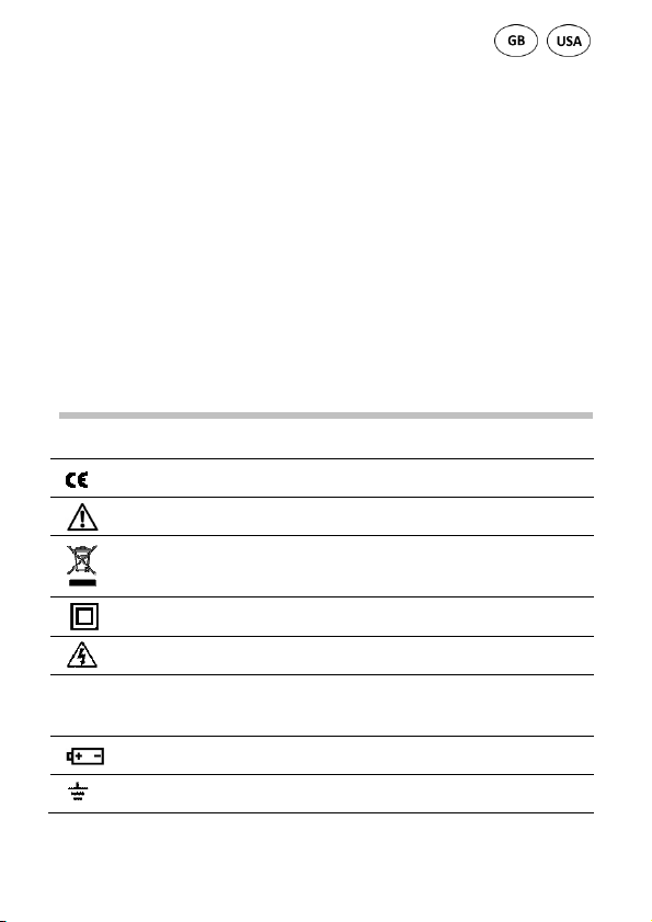
4. Erläuterungen der Symbole am Gerät
Übereinstimmung mit der EU
-
Niederspannungsrichtlinie
Dieses Produkt darf am Ende seiner Lebensdauer nicht in den
Schutzisolierung: Alle spannungsführenden Teile sind doppelt
Das Gerät ist für Messungen an der Quelle der
(EN-61010)
Gefahr! Beachten Sie die Hinweise der Bedienungsanleitung!
normalen Haushaltsabfall entsorgt werden, sondern muss an einer
Sammelstelle für das Recycling von elektrischen und
elektronischen Geräten abgegeben werden.
isoliert
Achtung! Gefährliche Spannung! Gefahr von Stromschlag.
CAT IV
Niederspannungsinstallation vorgesehen. Beispiele sind Zähler
und Messungen an primären Überstromschutzeinrichtungen und
Rundsteuergeräten.
Batteriefach
Erdungssymbol (max. Spannung gegen Erde)
DE 5
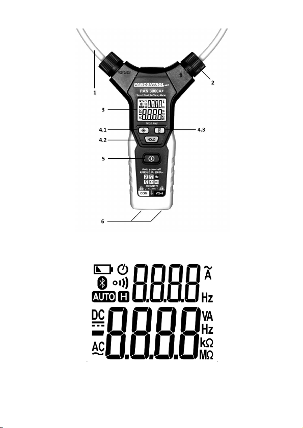
5. Bedienelemente und Anschlussbuchsen
(siehe Fig. 1)
1. Flexible Zange
2. Verschluss
3. Hauptanzeige / Nebenanzeige (kleine Ziffern)
4. Funktionstasten
4.1 Hintergrundbeleuchtung
4.2 Data hold
4.3 Messpunktbeleuchtung
5. Hauptschalter
6. Eingangsbuchsen
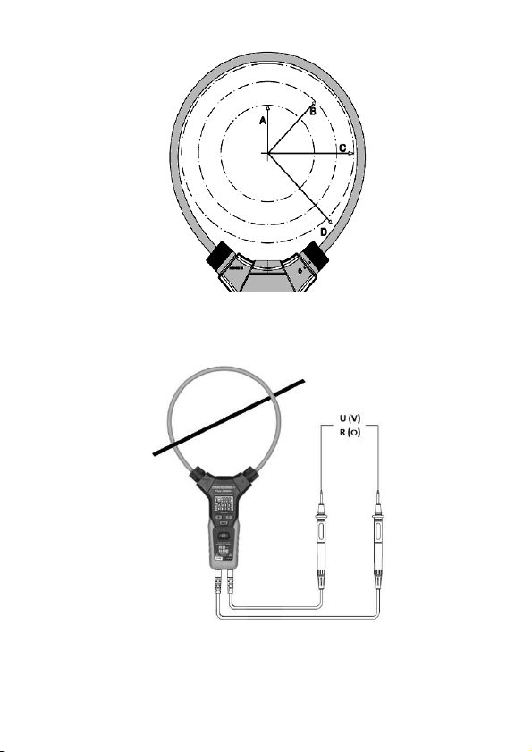
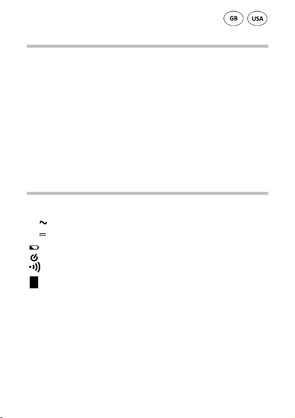
6. Das Display und seine Symbole
(siehe Fig. 2)
AC Wechselspannung/-strom
DC Gleichspannung
Batterie schwach
Betriebsanzeige / Automatische Abschaltung
Durchgangsprüfung aktiv
H Data hold
Widerstandsmessung
Ω
Hz Frequenzmessung
A Wechselstrommessung
V Gleichspannungsmessung / Wechselspannungsmessung
OL Überlastanzeige
Nebenanzeige (kleine Ziffern)
Bei diesem Gerät werden nicht alle, im Bild dargestellten Symbole, verwendet.
DE 6

7. Technische Daten
Anzeige LCD mit Hintergrundbeleuchtung
3 3/4 Stellen (bis 5999)
Überlastanzeige OL
Polarität automatisch (Minuszeichen für negative
Polarität)
Messrate 3 / s
Ansprechzeit 0,5 s
Kategorie CAT IV 600 V
max. Spannung gegen Erde 600 V
Durchgangsprüfung Bei einem Widerstand < 50 Ω hören Sie
einen Signalton.
Prüfstrom ca. 1 mA
Spannung des offenen
Schaltkreises
Automatische Abschaltung ca. 5 Min.
Eingangsimpedanz 2 MΩ
Stromversorgung 3 x 1,5 V (AAA Batterie(n))
Betriebsbedingungen 0 - 40°C (32 - 104°F) / < 80% Luftfeuchte
Seehöhe max. 2000 m
Lagerbedingungen -10 - 60°C (14 - 140°F) (Entfernen Sie die
Gewicht 220 g (mit Batterie(n))
Abmessungen 178 x 324 x 30 mm
ca. 0,8 V
Batterie(n) wenn Luftfeuchte > 80%)
DE 7

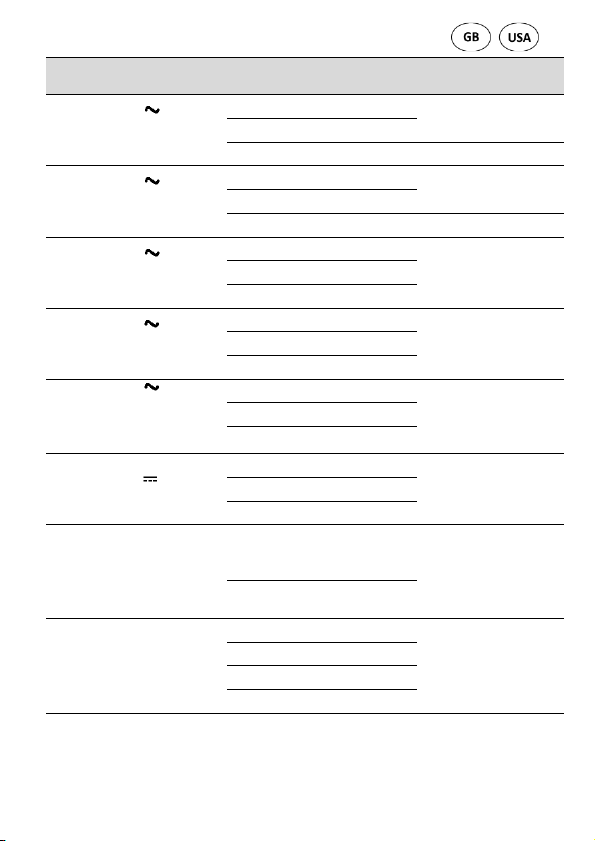
Genauigkeit in %
Frequenz
(Hz)
Wechselspannung
:
Funktion Bereich Auflösung
Wechselstrom (A )
40- 65 Hz *)
min. 0,1 A
Wechselstrom (A )
65 - 200 Hz *)
min. 0,1 A
Wechselstrom (A )
200 - 1000 Hz *)
min. 0,1 A
Wechselspannung (V )
45 - 65 Hz *)
min. 0,5 V
Wechselspannung (V )
40 - 2000 Hz *)
(< 45 Hz, > 65 Hz)
min. 0,5 V
Gleichspannung (V )
min. 0,2 V
Wechselstrom:
min. 3 A /40 Hz - 1 kHz
min. 0,5 V / 40 Hz - 10 kHz
Widerstand (Ω)
*) Die Daten für andere Frequenzen sind derzeit nicht verfügbar.
60 A 0,01 A
600 A 0,1 A
3000 A 1 A ±(2,0% + 5 digits)
60 A 0,01 A
600 A 0,1 A
3000 A 1 A ±(3,0% + 5 digits)
60 A 0,01 A
600 A 0,1 A
3000 A 1 A
6 V 0,001 V
600 V 0,1 V
6 V 0,001 V
60 V 0,01 V
600 V 0,1 V
6 V 0,001 V
600 V 0,1 V
40 - 1000 Hz 0,1 Hz
1 kHz-10kHz 1 Hz
6 kΩ 0,001 kΩ
60 kΩ 0,01 kΩ
600 kΩ 0,1 kΩ
6 MΩ 0,001 MΩ
DE 8
vom angezeigten
Wert
<10 A ±(2,0% + 10 d)
±(1,5% + 5 digits)
±(2,5% + 5 digits)
±(3,0% + 5 digits)
> 1000 A Daten
nicht verfügbar
±(1,2% + 3 digits) 60 V 0,01 V
±(2,0% + 5 digits)
±(0,8% + 3 digits) 60 V 0,01 V
±(0,5% + 2 digits)
±(1% + 3 digits)

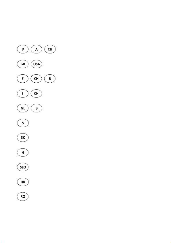
Genauigkeit in Abhängigkeit der Position
(siehe Fig. 3)
Messposition Abweichung
A 35 mm ±0.5%
B 50 mm ±1.5%
C 60 mm ±2.0%
D >60 mm ±5.0%
8. Bedienung
Allgemeine Informationen
Schalten Sie das Messgerät stets aus (OFF), wenn Sie es nicht benutzen.
Beachten Sie bitte die Skizzen auf den ersten Seiten dieser
Bedienungsanleitung.
Um das Gerät ein- bzw. auszuschalten betätigen Sie den Hauptschalter (5), bis
ein kurzer Piep ertönt.
Achtung!
Messen Sie keine Spannungen, während auf dem Schaltkreis ein Motor einoder ausgeschaltet wird. Das kann zu großen Spannungsspitzen und damit zur
Beschädigung des Messgeräts führen.
Stromschlaggefahr. Die Prüfspitzen sind möglicherweise nicht lang genug, um
die spannungsführenden Teile innerhalb einiger 230V Steckdosen zu berühren,
da diese sehr tief eingesetzt sind. Als Ergebnis kann die Ablesung 0 Volt
anzeigen, obwohl tatsächlich Spannung anliegt. Vergewissern Sie sich, dass die
Prüfspitzen die Metallkontakte in der Steckdose berühren, bevor Sie davon
ausgehen, dass keine Spannung anliegt.
DE 9

In der Nähe von Geräten, welche elektromagnetische Streufelder erzeugen
(z.B. Schweißtransformator, Zündung, etc.), kann das Display ungenaue oder
verzerrte Werte anzeigen.
Automatische / manuelle Bereichswahl
Wenn das Messgerät eingeschaltet wird, befindet es sich in der Betriebsart
"Auto Ranging" (automatische Bereichswahl). Hierbei erkennt das Gerät
selbsttätig den geeigneten Messbereich. Eine manuelle Bereichswahl ist nicht
möglich.
Data hold
Wenn die Anzeige während der Messung nicht einsehbar ist, kann der
Messwert mit der HOLD -Taste (4.2) festgehalten werden. Danach kann das
Messgerät vom Messobjekt entfernt und der auf der Anzeige gespeicherte
Wert abgelesen werden.
Um den Messwert am Display „einzufrieren“, drücken Sie einmal die
Funktionstaste HOLD. Das Symbol "H" erscheint in der Anzeige. Zur
Deaktivierung nochmals die HOLD Taste drücken.
Hintergrundbeleuchtung
Um die Hintergrundbeleuchtung ein- bzw. auszuschalten betätigen Sie die
Taste (4.1).
Messpunktbeleuchtung
Bei schlechten Lichtverhältnissen können Sie den Messpunkt beleuchten.
Betätigen Sie dazu die Taste (4.3).
Automatische Abschaltung
Wenn keine weiteren Messungen durchgeführt werden, schaltet sich das
Gerät nach 5 Minuten automatisch ab.
DE 10

Gleichspannungsmessung, Wechselspannungsmessung,
Widerstandsmessung und Durchgangsprüfung
Das Gerät detektiert Gleichspannung, Wechselspannung oder Widerstand
automatisch. Wechselstrom wird über die flexible Zange erkannt.
(Reihenfolge: Wechselspannung, Gleichspannung, Wechselstrom, Widerstand
/ Durchgangstest)
Gleichspannung: Bei umgekehrter Polarität wird am Display ein "-" vor dem
Wert angezeigt.
Wechselspannung/-strom: Bei der Messung von Wechselspannung /
Wechselstrom wird in der Nebenanzeige die Frequenz angezeigt.
Widerstand / Durchgangsprüfung: Bei einem Widerstand < 50 Ω hören Sie
einen Signalton.
1. Schalten Sie das Gerät mit dem Hauptschalter (5) ein.
2. Schließen Sie den Bananenstecker des schwarzen Prüfkabels an der
COM-Buchse und den Bananenstecker des roten Prüfkabels an der V-,
Ω-Buchse an.
3. Berühren Sie mit den Prüfspitzen die Messpunkte.
4. Wenn sich der Anzeigewert stabilisiert, lesen Sie das Display ab.
Wechselstrommessung
Wechselstrommessungen erfolgen nur über die flexible Zange.
Gleichstrommessungen sind nicht möglich.
Messen Sie immer nur an einer Ader bzw. einem Leiter. Das Einschließen von
mehr als einem Leiter ergibt eine Differenzstrommessung (ähnlich dem
Identifizieren von Leckströmen).
Sind andere stromdurchflossene Leiter in der Nähe, könnten diese die
Messung beeinflussen. Halten Sie aus diesem Grund einen möglichst großen
Abstand zu anderen Leitern.
DE 11

Nach einer Strommessung dauert es einige Sekunden, bis die Anzeige wieder
auf Null zurückgeht. Dieser Effekt ergibt sich aus der true RMS-Funktion und ist
normal.
1. Schalten Sie das Gerät mit dem Hauptschalter (5) ein.
2. Durch Drehen des Verschlusses (2) öffnen Sie die flexible Zange.
3. Schließen Sie die Messzangen wieder und bringen Sie den Leiter möglichst
mittig in die Zangenöffnung.
4. Wenn sich der Anzeigewert stabilisiert, lesen Sie das Display ab.
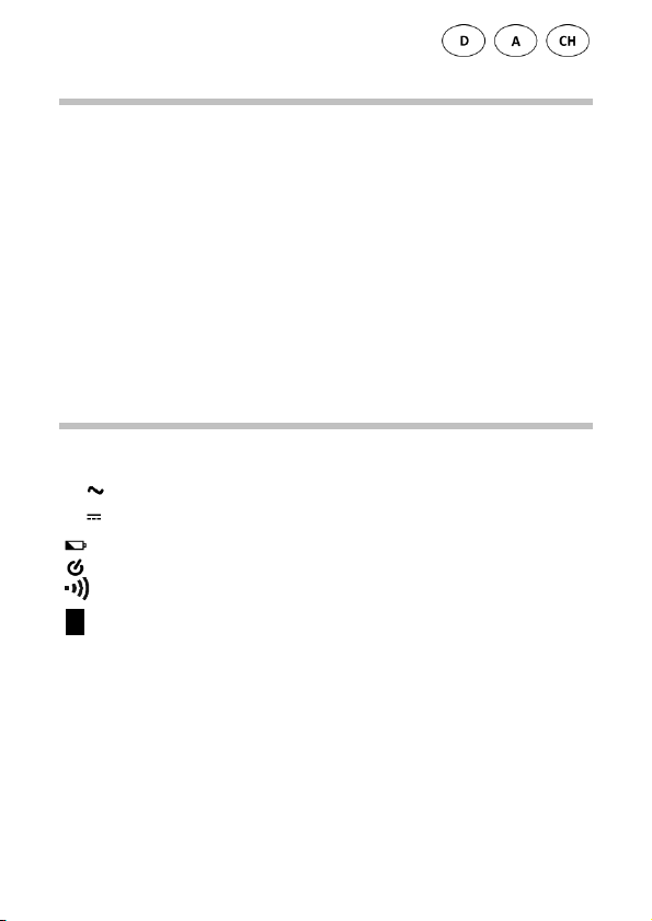
Bei gleichzeitiger Messung von Wechselstrom über die flexible Zange und
Spannung (AC/DC) oder Widerstand über die Anschlussbuchsen, wird in der
Nebenanzeige der Strom, statt der Frequenz, und in der Hauptanzeige die
Spannung oder der Widerstand angezeigt.
(siehe Fig. 4)
9. Instandhaltung
Reparaturen an diesem Gerät dürfen nur von qualifizierten Fachleuten
ausgeführt werden.
Austauschen der Batterie(n)
Sobald das Batteriesymbol oder BATT am Display erscheint, ersetzen Sie die
Batterie.
1. Öffnen Sie das Batteriefach.
2. Setzen Sie die Batterie in die Halterung ein und beachten Sie die richtige
Polarität.
3. Schließen Sie das Batteriefach wieder.
4. Entsorgen Sie leere Batterien umweltgerecht.
DE 12

Wenn Sie das Gerät längere Zeit nicht benutzen, entfernen Sie die Batterie.
Reinigung
Bei Verschmutzung reinigen Sie das Gerät mit einem feuchten Tuch und etwas
Haushaltsreiniger. Achten Sie darauf, dass keine Flüssigkeit in das Gerät dringt!
Keine aggresiven Reinigungs- oder Lösungsmittel verwenden!
10. Gewährleistung und Ersatzteile
Für dieses Gerät gilt die gesetzliche Gewährleistung von 2 Jahren ab
Kaufdatum (lt. Kaufbeleg). Reparaturen an diesem Gerät dürfen nur durch
entsprechend geschultes Fachpersonal durchgeführt werden. Bei Bedarf an
Ersatzteilen sowie bei Fragen oder Problemen wenden Sie sich bitte an Ihren
Fachhändler oder an:
Irrtum und Druckfehler vorbehalten.
2017-11
DE 13

Manual
PAN 3000A+
Flexible digital current pliers - True RMS

C
ONTENTS
1. Introduction ............................................................................................2
2. Scope of delivery.....................................................................................3
3. Safety Instructions ..................................................................................3
4. Symbols Description ...............................................................................4
5. Panel Description ....................................................................................5
6. Symbols of the Display ............................................................................5
7. General Specifications ............................................................................6
8. Operating Instructions ............................................................................8
9. Maintenance ......................................................................................... 11
10. Guarantee and Spare Parts ................................................................... 13
1. Introduction
Thank you for purchasing PANCONTROL. Since 1986 the PANCONTROL brand is
synonymous with practical, economical and professional measuring
instruments. We hope you enjoy using your new product and we are
convinced that it will serve you well for many years to come.
Please read this operating manual carefully before using the device to become
familiar with the proper handling of the device and to prevent faulty
operations. Please follow all the safety instructions. Nonobservance cannot
only result in damages to the device but in the worst case can also be harmful
to health.
The PAN 3000A+ is an intelligent, flexible current measuring plier. It can
automatically detect incoming signals without the user having to select a
measurement function or a measuring range.
Functions: Alternating current, alternating voltage, DC voltage, frequency,
resistance and continuity test
The technical progress is subject to change.
EN 2

2. Scope of delivery
After unpacking please check the package contents for transport damage and
completeness.
1. Measurement device
2. Test leads
3. Battery(s)
4. Operating manual
3. Safety Instructions
To ensure the safe use of the device, please follow all the safety and operating
instructions given in this manual.
• Before using the device, make sure that test leads and the device are in
good condition and the device is working properly (e.g. by connecting to
known voltage sources).
• The device may not be used if the housing or the test leads are damaged,
if one or more functions are not working, if functions are not displayed, or
if you suspect that something is wrong.
• If the safety of the user cannot be guaranteed, the device may not be
operated and secured against use.
• While using this device, hold the test leads only behind the finger guards -
do not touch the probes.
• Never ground yourself while making electrical measurements. Do not
touch any exposed metal pipes, fittings etc., which could have a ground
potential. Ensure that your body is isolated by using dry clothes, rubber
shoes, rubber mats or other approved insulation materials.
• Operate the device in a way that it is not difficult to operate the network
separators.
• Never connect the device to voltage or current sources that exceed the
specified maximum values.
EN 3
• If the battery symbol appears in the display, replace the battery
This product should not be disposed alon
g with normal domestic
The device is designed for making measurements at sources of low
immediately.
• Always switch off the appliance and remove the test leads from all voltage
sources before opening the device to exchange the battery or the fuse.
• Never use the device with the rear cover removed or with the battery and
fuse compartment open!
• Do not use the device outdoors, in humid surroundings or in
environments that are subjected to extreme temperature fluctuations.
• Do not store the device in places which are exposed to direct sunlight.
• Remove the battery if the device is not used for a long time.
• If changes or modifications are made to the device, the operational safety
is no longer guaranteed and the warranty becomes void.
4. Symbols Description
Conforms to the relevant European Union directive (EN-61010)
Risk of Danger. Important information See instruction manual
waste at the end of its service life but should be handed over at a
collection point for recycling electrical and electronic devices.
Product is protected by double insulation
Attention! Hazardous voltage. Risk of electric shock.
CAT IV
voltage installations. Examples are meters and measurements on
primary overload protection devices and ripple control devices.
Battery compartment
Ground / Earth (max. voltage to earth)
EN 4
5. Panel Description
(Note Fig. 1)
1. Flexible clamp
2. Closure
3. Maindisplay / Sidedisplay (small numbers)
4. Function keys
4.1 backlight
4.2 Data hold
4.3 Point Illumination
5. Main switch
6. Input terminal
6. Symbols of the Display
(Note Fig. 2)
AC AC voltage / current
DC DC voltage
Battery low
Operation indicator / Auto power off
Audible continuity test active
H Data hold
Resistance measurement
Ω
Hz Frequency measurement
A AC Current measurement
V DC Voltage measurement / AC Voltage measurement
OL Overload indicator
Sidedisplay (small numbers)
This device does not use all the symbols shown in the image.
EN 5

7. General Specifications
Display LCD with backlight
3 3/4 Digits (to 5999)
Overload indicator OL
Polarity automatically (minus sign for negative
polarity)
Measuring rate 3 / s
response time 0,5 s
Category CAT IV 600 V
max. voltage to earth 600 V
Continuity test If the resistance is < 50 Ω, you hear an
audible signal.
Test current ca. 1 mA
Open circuit voltage ca. 0,8 V
Auto power off ca. 5 Min.
Internal impedance 2 MΩ
Power supply 3 x 1,5 V (AAA Battery(s))
Operating temperatute 0 - 40°C (32 - 104°F) / < 80% Humidity
Altitude max. 2000 m
Storage temperature -10 - 60°C (14 - 140°F) (Remove the battery if
Humidity > 80%)
Weight 220 g (with Battery(s))
Dimensions 178 x 324 x 30 mm
EN 6
Function Range Resolution
Accuracy of the
Frequency
(Hz)
AC voltage
:
Ω
AC current (A )
40- 65 Hz *)
min. 0,1 A
AC current (A )
65 - 200 Hz *)
min. 0,1 A
AC current (A )
200 - 1000 Hz *)
min. 0,1 A
AC voltage (V )
45 - 65 Hz *)
min. 0,5 V
AC voltage (V )
40 - 2000 Hz *)
(< 45 Hz, > 65 Hz)
min. 0,5 V
DC voltage (V )
min. 0,2 V
60 A 0,01 A
600 A 0,1 A
3000 A 1 A ±(2,0% + 5 digits)
60 A 0,01 A
600 A 0,1 A
3000 A 1 A ±(3,0% + 5 digits)
60 A 0,01 A
600 A 0,1 A
3000 A 1 A
6 V 0,001 V
600 V 0,1 V
6 V 0,001 V
60 V 0,01 V
600 V 0,1 V
6 V 0,001 V
600 V 0,1 V
value displayed in %
±(1,5% + 5 digits)
<10 A ±(2,0% + 10 d)
±(2,5% + 5 digits)
±(3,0% + 5 digits)
> 1000 A Data not
available
±(1,2% + 3 digits) 60 V 0,01 V
±(2,0% + 5 digits)
±(0,8% + 3 digits) 60 V 0,01 V
AC current:
min. 3 A /40 Hz - 1 kHz
min. 0,5 V / 40 Hz - 10 kHz
Resistance (Ω)
*) The data for other frequencies is currently unavailable.
40 - 1000 Hz 0,1 Hz
1 kHz-10kHz 1 Hz
60 kΩ 0,01 kΩ
600 kΩ 0,1 kΩ
6 MΩ 0,001 MΩ
0,001 kΩ
6 k
EN 7
±(0,5% + 2 digits)
±(1% + 3 digits)

Precision depending on position
(Note Fig. 3)
Measuring position Deviation
A 35 mm ±0.5%
B 50 mm ±1.5%
C 60 mm ±2.0%
D >60 mm ±5.0%
8. Operating Instructions
General information
Always switch OFF the device when it is not in use.
Please refer to the sketches on the first pages of this manual.
To switch the unit on or off, press the main switch (5) until a short beep is
heard.
Attention!
Avoid voltage measuring in electrical circuits while motors are switched on or
off. The stress-spikes can damage the instrument.
Hazardous voltage! The probes may not be long enough to touch the hot parts
in some 230V wall sockets as they are deep inside. As a result, the reading can
show 0 volts. Make sure that the probes touch the metallic contacts in the
socket before assuming that voltage has not been applied.
Devices like welding transformer, car ignition system, etc. could produce stray
electromagnetic fields which could adulterate the result of a measurement.
EN 8

Automatic/Manual Range selection
When the meter is switched on, it is in the auto ranging mode. The device
automatically detects the appropriate measuring range. Manual range
selection is not possible.
Data hold
If the reading could not be read during measurement due to difficult operation
the „HOLD“-button (4.2) could be pressed to freeze the display reading. Press
the „HOLD“-button to freeze the display reading. The "H" symbol appears in
the display. Press the „HOLD“-button again to return to standard operation.
Backlight
To turn the backlight on or off, press the button (4.1).
Point Illumination
In low light conditions, you can illuminate the point. To do this, press the
button (4.3).
Auto power off
If no further measurements are carried out, the device switches off
automatically after 5 minutes.
DC Voltage measurement, AC Voltage measurement, Resistance
measurement and Continuity test
The device detects DC voltage, alternating voltage or resistance automatically.
Alternating current is detected via the flexible pliers.
(Sequence: AC voltage, DC voltage, AC current, resistance / continuity test)
DC voltage:
AC voltage / current: When measuring alternating voltage/alternating current,
the frequency is displayed in the secondary display.
If the polarity is reversed a "-" is displayed.
EN 9

Resistance / Continuity test: If the resistance is < 50 Ω, you hear an audible
signal.
1. Switch the unit on with the main switch (5).
2. Attach the pin-plug of the black test lead to the COM-jack and the
pin-plug of the red test lead to the V-, Ω-jack.
3. Touch the measuring points with the probe tips.
4. Once the reading stabilizes, read the value.
AC Current measurement
Alternating current measurements are only carried out via the flexible pliers.
DC measurements are not possible.
Always measure current on one conductor only. Covering more than one
conductor results in measuring differential current (like identifying leakage
current). To avoid measuring errors related to other hot conductors, please
observe maximum phase-to-phase clearance.
After a current measurement, it takes a few seconds for the display to return
to zero. This effect results from the true RMS function and is normal.
1. Switch the unit on with the main switch (5).
2. You open the flexible clamp by turning the bolt (2).
3. Clamp the wire placed in the opening and close the flexible clamp again.
4. Once the reading stabilizes, read the value.
With simultaneous measurement of alternating current via the flexible pliers
and voltage (AC/DC) or resistance via the connection sockets, the secondary
display shows the current instead of the frequency and in the main display the
voltage or the resistance.
(Note Fig. 4)
EN 10

9. Maintenance
Only authorized service technicians may repair the instrument.
Changing the battery(s)
Replace the battery(s) when the battery symbol or BATT is displayed on the
LCD.
1. Open the battery compartment.
2. Replace the battery. Mind the correct polarity.
3. Close the battery compartment.
4. Disposal of the flat battery should meet environmental standards.
Remove the battery if the device is not used for a long time.
Cleaning
If the instrument is dirty after daily usage, it is advised to clean it by using a
humid cloth and a mild household detergent. Prior to cleaning, ensure that
instrument is switched off and disconnected from external voltage supply and
any other instruments connected. Never use acid detergents or dissolvent for
cleaning.
10. Guarantee and Spare Parts
PANCONTROL instruments are subject to strict quality control. However,
should the instrument function improperly during daily use, your are protected
by a 24 months warranty from the date of purchase (valid only with invoice).
EN 11

Only trained technicians may carry out repairs to this device. In case of spare
part requirement or in case of queries or problems, please get in touch with
your vendor or:
Error and misprints reserved.
2017-11
EN 12

Manuel d'instructions
PAN 3000A+
Pince ampèremétrique numérique flexible - True
RMS

C
ONTENU
1. Introduction ............................................................................................2
2. Contenu de la livraison ...........................................................................3
3. Consignes générales de sécurité .............................................................3
4. Explications des symboles figurant sur l’appareil ....................................5
5. Eléments de commande et douilles de raccordement ............................5
6. L’écran et ses symboles ..........................................................................6
7. Caractéristiques techniques ....................................................................7
8. Utilisation ...............................................................................................9
9. Maintenance ......................................................................................... 12
10. Garantie et pièces de rechange ............................................................ 13
1. Introduction
Merci d’avoir acheté un appareil PANCONTROL. La marque PANCONTROL est
disponible depuis 1986 pour la pratique, peu coûteux et instruments de
mesure professionnels. pratiques et bon marché. Nous vous souhaitons
beaucoup de plaisir lors de l’utilisation de cet appareil et nous sommes
convaincus qu’il vous sera d’une grande utilité durant de nombreuses années.
Veuillez lire attentivement le manuel d’utilisation dans son intégralité avant la
première mise en service de l’appareil en vue de vous familiariser avec la
manipulation correcte de l’appareil et d’éviter toute utilisation incorrecte. Il
est impératif de respecter toutes les consignes de sécurité. Un non respect de
celles-ci peut provoquer des dommages sur l'appareil et entraîner des
dommages sanitaires.
Conservez soigneusement la présente notice d'utilisation afin de la compulser
ultérieurement ou de pouvoir la transmettre avec l'appareil.
FR 2

Le PAN 3000A+ est un pince intelligent et flexible de mesure de courant. Il
peut détecter automatiquement les signaux entrants sans que l'utilisateur
doive sélectionner une fonction de mesure ou une plage de mesure.
Fonctions: courant alternatif, tension alternative, tension de c.c, fréquence,
résistance et contrôle de continuité
Le progrès technique est sujet à changement.
2. Contenu de la livraison
Veuillez vérifier au déballage de votre commande qu'elle n'a pas subi de
dommages et qu'elle est bien complète.Veuillez vérifier au déballage de votre
commande qu'elle n'a pas subi de dommages et qu'elle est bien complète.
1. Appareil de mesure
2. Câble de contrôle
3. Pile(s)
4. Manuel d'instructions
3. Consignes générales de sécurité
En vue de manipuler l’appareil en toute sécurité, nous vous prions de
respecter les consignes de sécurité et d'utilisation figurant dans le présent
manuel.
• Assurez vous, avant l'utilisation, que les câbles de contrôle et l'appareil ne
sont pas endommagés et qu'ils fonctionnent parfaitement. (par ex. sur
des sources de courant connues).
• L’appareil ne peut pas être utilisé si le boîtier ou le câble de contrôle est
endommagé, si une ou plusieurs fonctions sont défaillantes, si aucune
fonction n’est affichée ou si vous soupçonnez un problème quelconque.
• Quand la sécurité de l’utilisateur ne peut être garantie, il convient de
mettre l’appareil hors service et de prendre les mesures nécessaires pour
éviter qu’il soit réutilisé.
FR 3

• Lors de l‘utilisation du présent appareil, les câbles de contrôle ne peuvent
être touchés qu’au niveau des poignées figurant derrière le
protège-doigts ; ne touchez pas les pointes de touche.
• Ne jamais mettre à la terre lors de la réalisation de mesures électriques.
Ne touchez pas de tubes métalliques, d'armatures ou d'autres objets
semblables pouvant avoir un potentiel de terre. Isolez votre corps par le
biais de vêtements secs, de chaussures en caoutchouc, de tapis en
caoutchouc ou d'autres matériaux d'isolation contrôlés.
• Veuillez placer l’appareil de sorte que la commande des dispositifs de
sectionnement d’alimentation soit facilement accessible.
• N'appliquez jamais sur un appareil de mesure une tension ou un courant
dépassant les valeurs maximales indiquées sur l’appareil.
• Vous êtes priés de remplacer immédiatement les piles lorsque le symbole
de pile apparaît à l’écran.
• Toujours éteindre l’appareil et retirer les cordons de toutes les sources de
tension avant d’ouvrir l’appareil pour échanger la batterie ou le fusible.
• N’utilisez jamais l’appareil de mesure sans le cache arrière ou avec le
compartiment à piles ou à fusible ouvert !
• N’utilisez pas l’appareil à l’air libre, dans un environnement humide ou
dans un environnement subissant d’importantes variations de
températures.
• Ne stockez pas l’appareil dans un endroit soumis à des rayonnements
directs du soleil.
• En cas de non-utilisation prolongée de l’appareil, veuillez retirer la pile.
• La sécurité de fonctionnement de l'appareil ne sera plus garantie en cas
de modification de l’appareil. et les droits de garantie expireront.
FR 4

4. Explications des symboles figurant sur
Conformité avec la réglementation CE concernant la basse tension
Ce produit ne doit pas être jeté avec les ordures ménagères
Double isolation : toutes les pièces de l
’appareil qui sont sous
L’appareil est également conçu pour effectuer des mesures à la
l’appareil
(EN-61010)
Danger ! Respectez les consignes du manuel d'utilisation !
lorsqu’il est arrivé en fin de vie mais il doit être apporté au centre
de collecte pour le recyclage des appareils électriques et
électroniques.
tension disposent d’une double isolation.
Attention ! Tension dangereuse ! Danger d'électrocution.
CAT IV
source de l’installation de basse tension. Par exemple, les
compteurs et les mesures sur les systèmes de régulation de
l'ondulation et les dispositifs de protection contre les surintensités
primaires.
Compartiment à piles
Symbole de mise à la terre (tension max. contre terre)
5. Eléments de commande et douilles de
raccordement
(Note Fig. 1)
1. Pince flexible
2. Fermeture
3. Affichage principal / Affichage secondaire (petits nombres)
FR 5

4. Touches de fonction
4.1 Rétro-éclairage
4.2 Attente de données
4.3 Illumination ponctuelle
5. Interrupteur principal
6. Prises d'entrée
6. L’écran et ses symboles
(Note Fig. 2)
AC Tension/courant alternatifs
DC Tension continue
Pile faible
Affichage de fonctionnement / Coupure automatique
Contrôle de continuité actif
H Attente de données
Mesure de la résistance
Ω
Hz Mesure de fréquence
A Mesure du courant alternatif
V Mesure tension continue / Mesure de tension alternative
OL Affichage de la surcharge
Affichage secondaire (petits nombres)
Cet appareil n'utilise pas tous les symboles affichés dans l'image.
FR 6

7. Caractéristiques techniques
Affichage LCD avec Rétro-éclairage
3 3/4 Chiffres (à 5999)
Affichage de la surcharge OL
Polarité automatiquement (signe moins pour la
polarité négative)
Vitesse de mesure 3 / s
temps de réponse 0,5 s
Catégorie CAT IV 600 V
tension max. contre terre 600 V
Contrôle de continuité En cas de résistance de < 50 Ω, un signal
sonore sera déclenché.
Courant d'essai ca. 1 mA
Tension en circuit ouvert ca. 0,8 V
Coupure automatique ca. 5 Min.
Impédance d'entrée 2 MΩ
Alimentation électrique 3 x 1,5 V (AAA Pile(s))
Conditions d'exploitation 0 - 40°C (32 - 104°F) / < 80% Humidité de l'air
Altitude max. 2000 m
Conditions de stockage -10 - 60°C (14 - 140°F) (Retirez la batterie si
Humidité de l'air > 80%)
Poids 220 g (avec Pile(s))
Dimensions 178 x 324 x 30 mm
FR 7

Fonction Région Résolution
Fréquence
(Hz)
Tension alternative
:
Courant alternatif (A )
40- 65 Hz *)
min. 0,1 A
Courant alternatif (A )
65 - 200 Hz *)
min. 0,1 A
Courant alternatif (A )
200 - 1000 Hz *)
min. 0,1 A
Tension alternative (V
)
45 - 65 Hz *)
min. 0,5 V
Tension alternative (V
)
40 - 2000 Hz *)
(< 45 Hz, > 65 Hz)
min. 0,5 V
Tension continue (V )
min. 0,2 V
60 A 0,01 A
600 A 0,1 A
3000 A 1 A ±(2,0% + 5 digits)
60 A 0,01 A
600 A 0,1 A
3000 A 1 A ±(3,0% + 5 digits)
60 A 0,01 A
600 A 0,1 A
3000 A 1 A
6 V 0,001 V
60 V 0,01 V
600 V 0,1 V
6 V 0,001 V
60 V 0,01 V
600 V 0,1 V
6 V 0,001 V
600 V 0,1 V
Précision en % de
la valeur affichée
±(1,5% + 5 digits)
<10 A ±(2,0% + 10 d)
±(2,5% + 5 digits)
±(3,0% + 5 digits)
> 1000 A Données
non disponibles
±(1,2% + 3 digits)
±(2,0% + 5 digits)
±(0,8% + 3 digits) 60 V 0,01 V
Courant alternatif:
min. 3 A /40 Hz - 1 kHz
min. 0,5 V / 40 Hz - 10 kHz
Résistance (Ω)
*) Les données pour d'autres fréquences sont actuellement indisponibles.
40 - 1000 Hz 0,1 Hz
1 kHz-10kHz 1 Hz
6 kΩ 0,001 kΩ
60 kΩ 0,01 kΩ
600 kΩ 0,1 kΩ
6 MΩ 0,001 MΩ
FR 8
±(0,5% + 2 digits)
±(1% + 3 digits)

Précision en fonction de la position
(Note Fig. 3)
Position de mesure Écart
A 35 mm ±0.5%
B 50 mm ±1.5%
C 60 mm ±2.0%
D >60 mm ±5.0%
8. Utilisation
Informations générales
Mettez l’appareil hors service (OFF) si vous ne l’utilisez pas.
Veuillez vous reporter aux croquis des premières pages de ce manuel.
Pour allumer ou éteindre l'appareil, appuyez sur l'interrupteur principal (5)
jusqu'à ce qu'un bref bip se fasse entendre.
Attention!
Ne mesurez pas de tensions lorsque un moteur est commuté ou mis hors
service sur le circuit. Des pics de tension importants peuvent être générés et
endommager l'appareil de mesure.
Risque de choc électrique. Les pointes de touche ne sont éventuellement pas
suffisamment longues pour entrer en contact avec des éléments conducteurs à
l'intérieur de certaines prises de courant de 230V étant donné que ceux-ci sont
insérés très profondément. Le résultat de la lecture peut afficher 0 volt, bien
que la tension soit effectivement appliquée. Assurez-vous que les pointes de
touche soient bien en contact avec les contacts métalliques à l'intérieur de la
prise avant de supposer qu'il n'y a pas de tension.
FR 9

A proximité d'appareils générant des champs électromagnétiques (par ex.
transformateur de soudage, allumage, etc.), il se peut que l'écran affiche des
valeurs imprécises et de distorsion.
Sélection de plage automatique/manuel
Lorsque le compteur est allumé, il est en mode "Auto Ranging" (sélection
automatique de la plage). L'appareil détecte automatiquement la plage de
mesure appropriée. La sélection manuelle de la cuisinière n'est pas possible.
Attente de données
Lorsque l’affichage n’est pas visible durant la mesure, la valeur de mesure peut
être déterminée à l'aide de la touche HOLD (4.2). Ensuite, l'appareil de mesure
peut être retiré de l’objet à mesurer et la valeur enregistrée sur l'affichage
peut être relevée.
En vue de « geler » la valeur de mesure à l’écran, il convient de cliquer sur la
touche de fonction HOLD. Le symbole "H" apparaît sur l'afficheur. Pour
désactiver cette fonction, cliquez à nouveau sur la touche HOLD.
Rétro-éclairage
Pour allumer ou éteindre le rétro-éclairage, appuyez sur la touche (4.1).
Illumination ponctuelle
Dans des conditions de faible luminosité, vous pouvez illuminer le point. Pour
ce faire, appuyez sur la touche (4,3).
Coupure automatique
Si aucune autre mesure n'est effectuée, l'appareil s'éteint automatiquement
après 5 minutes.
FR 10

Mesure tension continue, Mesure de tension alternative,
Mesure de la résistance et Contrôle de continuité
L'appareil détecte automatiquement la tension CC, la tension alternative ou la
résistance. Le courant alternatif est détecté par les pinces flexibles.
(séquence: tension alternée, tension CC, courant alternatif, résistance /
contrôle de continuité)
Tension continue: En cas de polarité inversée, le symbole "-" figurera devant la
valeur affichée à l’écran.
Tension/courant alternatifs: En mesurant la tension alternant/courant
alternatif, la fréquence est affichée dans l'affichage secondaire.
Résistance / Contrôle de continuité: En cas de résistance de < 50 Ω, un signal
sonore sera déclenché.
1. Mettez l'appareil en marche avec l'interrupteur principal (5).
2. Reliez la prise banane du câble de contrôle noir à la douille COM et la
prise banane du câble de contrôle rouge à la douille V, Ω.
3. Touchez les points de mesure avec les bouts de sonde.
4. Lorsque la valeur d'affichage s'est stabilisée, lisez sur l'écran.
Mesure du courant alternatif
Les mesures de courant alternatif ne sont effectuées qu'à l'aide des pinces
flexibles. Les mesures DC ne sont pas possibles.
Ne mesurer qu'au niveau d'un fil ou d'un conducteur seulement. L'intégration
de plus d'un conducteur donne une mesure de courant différentiel (identique
à l'identification des courants de fuite).
Si des composants ou des câbles conducteurs d'électricité sont à proximité, ces
derniers pourraient influencer la mesure. Pour cette raison maintenez un écart
le plus important possible avec les autres conducteurs.
Après une mesure de courant, il faut quelques secondes pour que l'affichage
retourne à zéro. Cet effet est dérivé de la fonction true RMS et est normal.
FR 11

1. Mettez l'appareil en marche avec l'interrupteur principal (5).
2. Vous ouvrez la pince flexible en tournant le boulon (2).
3. Fixer le fil placé dans l’ouverture et refermer la pince flexible.
4. Lorsque la valeur d'affichage s'est stabilisée, lisez sur l'écran.
Avec la mesure simultanée du courant alternatif par les pinces flexibles et la
tension (AC/DC) ou la résistance par les douilles de raccordement, l'affichage
secondaire indique le courant au lieu de la fréquence et dans l'affichage
principal la tension ou la résistance.
(Note Fig. 4)
9. Maintenance
Les réparations de cet appareil doivent être uniquement réalisées par des
personnels spécialisés et qualifiés.
Remplacement de la/des pile/s
Lorsque le symbole de piles ou BATT s’affiche à l’écran, il convient de
remplacer la pile.
1. Ouvrez le compartiment à piles.
2. Placez la pile neuve dans la fixation et tenez compte de la polarité
correcte.
3. Refermez le compartiment à piles.
4. Eliminez les piles vides conformément aux consignes de protection de
l’environnement.
En cas de non-utilisation prolongée de l’appareil, veuillez retirer la pile.
FR 12

Nettoyage
En cas d’encrassement, nettoyez l’appareil avec un chiffon humide et un peu
de détergent ménager. Veillez à ce qu'aucun liquide ne pénètre dans l'appareil
! N'employer aucun produit de nettoyage caustique ni solvant!
10. Garantie et pièces de rechange
Le présent appareil est couvert par une garantie légale de 2 années à compter
de la date d’achat (conformément à la facture d’achat). Les réparations sur cet
appareil ne doivent être effectuées que par du personnel technique
spécialement formé. En cas de besoin en pièces de rechange ainsi qu’en cas de
questions ou de problèmes, veuillez vous adresser à votre revendeur spécialisé
ou à :
Erreurs et fautes d’impression réservés.
2017-11
FR 13

Istruzioni per l’uso
PAN 3000A+
Pinza amperometrica digitale flessibile - True RMS

C
ONTENUTO
1. Introduzione ...........................................................................................2
2. Dotazione di fornitura .............................................................................3
3. Avvertenze generali per la sicurezza .......................................................3
4. Spiegazione dei simboli sull’apparecchio ................................................5
5. Elementi di comando e prese di allacciamento .......................................5
6. Il display e i suoi simboli .........................................................................6
7. Specifiche tecniche .................................................................................7
8. Uso..........................................................................................................9
9. Manutenzione in efficienza ................................................................... 12
10. Garanzia e pezzi di ricambio ................................................................. 13
1. Introduzione
Grazie per aver acquistato un apparecchio PANCONTROL. Il marchio
PANCONTROL è disponibile dal 1986 per strumenti di misura pratici, economici
e professionali. Ci auguriamo che siate soddisfatti del vostro nuovo
apparecchio e siamo convinti che vi fornirà ottime prestazioni per molti anni.
Leggete per intero e attentamente le presenti istruzioni per l'uso prima di
mettere in servizio per la prima volta l'apparecchio, al fine di prendere
confidenza con un corretto uso dell’apparecchio e evitare malfunzionamenti.
Seguite soprattutto tutte le avvertenze per la sicurezza. La mancata osservanza
può causare danni all'apparecchio e danni alla salute.
Conservate con cura le istruzioni per l'uso per consultarle in un momento
successivo oppure per poterle consegnare insieme all'apparecchio.
Il PAN 3000A+ è un intelligente, pinza di misura corrente flessibile. Può rilevare
automaticamente i segnali in entrata senza che l'utente debba selezionare una
funzione di misurazione o un campo di misura.
IT 2

Funzioni: corrente alternata, tensione alternata, tensione di CC, frequenza,
resistenza e prova di continuità
Il progresso tecnico è soggetto a cambiamenti.
2. Dotazione di fornitura
Dopo aver aperto l’imballo verificare l'eventuale presenza di danni da
trasporto e la completezza della dotazione di fornitura.
1. Il misuratore
2. Sonde test
3. Batteria(e)
4. Istruzioni per l’uso
3. Avvertenze generali per la sicurezza
Per garantire un uso sicuro dell’apparecchio seguire tutte le avvertenze per la
sicurezza e per l’uso contenute nel presente manuale.
• Prima dell'uso assicuratevi che le sonde test e l’apparecchio siano in
perfetto stato e l’apparecchio funzioni perfettamente (ad es. provandolo
su fonti di tensione note).
• Non è consentito continuare ad utilizzare l'apparecchio, se l'involucro o le
sonde test sono danneggiati, se sono venute meno una o più funzioni, se
non viene visualizzata alcuna funzione o se si teme che qualcosa non sia a
posto.
• Qualora non sia possibile garantire la sicurezza dell’utente, l’apparecchio
deve essere messo fuori servizio, impedendone un eventuale uso.
• Durante l’uso di questo apparecchio è consentito toccare le sonde test
solo sulle impugnature dietro al proteggi-dita – i puntali non vanno
toccati.
• Quando si eseguono misurazioni elettriche non collegarsi mai a terra. Non
toccate mai tubi metallici scoperti, raccordi, ecc. che potrebbero avere un
IT 3

potenziale di terra. L’isolamento del corpo si mantiene con un
abbigliamento asciutto, scarpe gommate, tappetini in gomma o altri
materiali isolanti testati.
• Utilizzate l'apparecchio in modo tale che l'uso di dispositivi di separazione
risulti complicato.
• Non applicate mai al tester tensioni o correnti eccedenti i valori massimi
indicati sull'apparecchio.
• Se compare il simbolo della batteria sul display, sostituirla
immediatamente.
• Sempre spegnere l'apparecchio e scollegare i cavetti da tutte le fonti di
tensione prima di aprire il dispositivo per scambiare la batteria o il
fusibile.
• Non usate mai l’apparecchio se il coperchio sul retro è stato tolto oppure
il vano batterie o dei fusibili è aperto.
• Non utilizzate l'apparecchio all'aperto, in ambienti umidi o in ambienti
esposti a forti sbalzi termici.
• Non tenete l’apparecchio sotto i raggi solari diretti.
• Se l’apparecchio non viene usato per un lungo periodo, togliete la
batteria.
• Se si modifica o altera l’apparecchio, non è più garantita la sicurezza
operativa. Inoltre si annullano tutti i diritti di garanzia e prestazione della
garanzia.
IT 4

4. Spiegazione dei simboli sull’apparecchio
Pericolo!! Osservate le av
vertenze contenute nelle istruzioni per
Al termine della sua durata di vita utile questo prodotto non deve
Isolamento di protezione: Tutti i componenti che conducono
L’apparecchio è concepito per le misurazioni sulla fonte
Conformità con la direttiva UE sulle basse tensioni (EN-61010)
l'uso!
essere smaltito insieme ai normali rifiuti domestici, ma conferito
in un centro di raccolta per il riciclaggio di apparecchi elettrici ed
elettronici.
tensione sono muniti di doppio isolamento
Attenzione! Tensione pericolosa! Pericolo di folgorazione.
CAT IV
dell’impianto a bassa tensione. Esempi sono i contatori e le
misurazioni su dispositivi primari di protezione da sovracorrente e
apparecchiature a comando centralizzato.
Vano batterie
Simbolo della messa a terra (tensione massima verso terra)
5. Elementi di comando e prese di
allacciamento
(Nota Fig. 1)
1. Pinza flessibile
2. Chiusura
3. Display principale / Display secondario (numeri piccoli)
4. Tasti funzione
4.1 Retroilluminazione
4.2 Funzione Data hold
4.3 Illuminazione puntiforme
IT 5

5. Interruttore principale
6. Prese d'ingresso
6. Il display e i suoi simboli
(Nota Fig. 2)
AC Tensione/corrente alternata
DC Tensione continua
Batteria scarica
Spia di stato / Spegnimento automatico
Prova di continuità attiva
H Funzione Data hold
Misurazione resistenza
Ω
Hz Misurazione frequenza
A Misurazione corrente alternata
V Misurazione tensione continua / Misurazione della tensione alternata
OL Indicatore di sovraccarico
Display secondario (numeri piccoli)
Questo dispositivo non utilizza tutti i simboli mostrati nell'immagine.
IT 6

7. Specifiche tecniche
Indicatore LCD con Retroilluminazione
3 3/4 Cifre (a 5999)
Indicatore di sovraccarico OL
Polarità automaticamente (segno meno per la
polarità negativa)
Ciclo di misura 3 / s
tempo di risposta 0,5 s
Categoria CAT IV 600 V
tensione massima verso
terra
Prova di continuità Se c'è un resistore < 50 Ω, si sente un bip.
Corrente di prova ca. 1 mA
Tensione a circuito aperto ca. 0,8 V
Spegnimento automatico ca. 5 Min.
Impedenza in ingresso 2 MΩ
Alimentazione di corrente 3 x 1,5 V (AAA Batteria(e))
Condizioni operative 0 - 40°C (32 - 104°F) / < 80% Umidità dell'aria
Altitudine max. 2000 m
Condizioni di stoccaggio -10 - 60°C (14 - 140°F) (Rimuovere la batteria
Peso 220 g (con Batteria(e))
Dimensioni 178 x 324 x 30 mm
600 V
se Umidità dell'aria > 80%)
IT 7

Funzione Area
Risoluzion
Precisione in % del
Frequenza
(Hz)
Tensione al
ternata
:
Ω
Corrente alternata (A )
40- 65 Hz *)
min. 0,1 A
Corrente alternata (A )
65 - 200 Hz *)
min. 0,1 A
Corrente alternata (A )
200 - 1000 Hz *)
min. 0,1 A
Tensione alternata (V )
45 - 65 Hz *)
min. 0,5 V
Tensione alternata (V )
40 - 2000 Hz *)
(< 45 Hz, > 65 Hz)
min. 0,5 V
Tensione continua (V )
min. 0,2 V
e
60 A 0,01 A
600 A 0,1 A
3000 A 1 A ±(2,0% + 5 digits)
60 A 0,01 A
600 A 0,1 A
3000 A 1 A ±(3,0% + 5 digits)
60 A 0,01 A
600 A 0,1 A
3000 A 1 A
6 V 0,001 V
600 V 0,1 V
6 V 0,001 V
60 V 0,01 V
600 V 0,1 V
6 V 0,001 V
600 V 0,1 V
valore visualizzato
±(1,5% + 5 digits)
<10 A ±(2,0% + 10 d)
±(2,5% + 5 digits)
±(3,0% + 5 digits)
> 1000 A Dati non
disponibili
±(1,2% + 3 digits) 60 V 0,01 V
±(2,0% + 5 digits)
±(0,8% + 3 digits) 60 V 0,01 V
Corrente alternata:
min. 3 A /40 Hz - 1 kHz
min. 0,5 V / 40 Hz - 10 kHz
Resistenza (Ω)
*) I dati per altre frequenze non sono attualmente disponibili.
40 - 1000 Hz 0,1 Hz
1 kHz-10kHz 1 Hz
6 k
60 kΩ 0,01 kΩ
600 kΩ 0,1 kΩ
6 MΩ 0,001 MΩ
IT 8
±(0,5% + 2 digits)
0,001 kΩ
±(1% + 3 digits)

Precisione a seconda della posizione
(Nota Fig. 3)
Posizione di misurazione Deviazione
A 35 mm ±0.5%
B 50 mm ±1.5%
C 60 mm ±2.0%
D >60 mm ±5.0%
8. Uso
Informazioni generali
Spegnere sempre l'apparecchio (OFF) se non lo utilizzate.
Si prega di fare riferimento agli schizzi sulle prime pagine di questo manuale.
Per accendere o spegnere l'unità, premere l'interruttore generale (5) fino a
udire un breve bip.
Attenzione!
Non misurate tensioni mentre un motore viene acceso o spento sul circuito di
commutazione. Ciò può provocare forti picchi di tensione e pertanto danni
all'apparecchio.
Pericolo di folgorazione. Probabilmente i puntali non sono abbastanza lunghi
per toccare le parti sotto tensione all'interno di alcune prese di corrente da
230V, in quanto sono inserite molto in profondità. Come risultato la lettura
può dare 0 volt, sebbene la tensione sia effettivamente presente. Accertatevi
che i puntali tocchino i contatti metallici all'interno della presa prima di
supporre che non vi sia tensione.
IT 9

In prossimità di apparecchi che producono campi di dispersione
elettromagnetici (ad es. trasformatore di saldatura, accensione, ecc.), sul
display possono comparire valori imprecisi o alterati).
Selezione automatica/manuale della gamma
Quando il contatore è acceso, è nel modo "Auto Ranging" (selezione
automatica della gamma). Il dispositivo rileva automaticamente il campo di
misura appropriato. La selezione manuale della gamma non è possibile.
Funzione Data hold
Se l’indicatore non è visibile durante la misurazione, il valore misurato può
essere mantenuto con il tasto HOLD (4.2). Dopodichè è possibile togliere il
tester dall'oggetto da misurare e leggere il valore memorizzato sull’indicatore.
Per „congelare“ sul display il valore misurato premete una volta il tasto
funzione HOLD. Sul display appare il simbolo "H". Per disattivare premete
ancora il tasto HOLD.
Retroilluminazione
Per attivare o disattivare la retroilluminazione, premere il tasto (4.1).
Illuminazione puntiforme
In condizioni di scarsa luminosità, è possibile illuminare il punto. Per farlo,
premete il tasto (4,3).
Spegnimento automatico
Se non si effettuano ulteriori misurazioni, l'apparecchio si spegne
automaticamente dopo 5 minuti.
IT 10

Misurazione tensione continua, Misurazione della tensione
alternata, Misurazione resistenza et Prova di continuità
Il dispositivo rileva automaticamente tensione continua, tensione alternata o
resistenza. La corrente alternata viene rilevata tramite le pinze flessibili.
(sequenza: tensione alternata, tensione continua, corrente alternata,
resistenza / prova di continuità
Tensione continua: In caso di polarità invertita sul display viene visualizzato un
"-" davanti al valore.
Tensione/corrente alternata: Quando si misura la tensione alternata/corrente
alternata, la frequenza viene visualizzata sul display secondario.
Resistenza / Prova di continuità: Se c'è un resistore < 50 Ω, si sente un bip.
1. Accendere l'apparecchio con l'interruttore generale (5).
2. Allacciare la spina a banana della sonda test nera alla presa COM e la
spina a banana della sonda test rossa alla presa V-, A-, Ω-.
3. Toccare i punti di misura con le punte della sonda.
4. Quando il valore visualizzato si stabilizza, leggere il display.
Misurazione corrente alternata
Le misure di corrente alternata vengono effettuate solo tramite le pinze
flessibili. Le misurazioni DC non sono possibili.
Misurate sempre un solo conduttore o filo. Includere più di un filo ha come
conseguenza una misurazione di corrente differenziale (simile
all'identificazione di correnti di fuga).
Se vi sono altri fili nelle vicinanze che conducono corrente, potrebbero
influenza la misurazione. Per questo motivo mantenete la massima distanza
possibile da altri fili.
Dopo una misurazione corrente, ci vogliono pochi secondi per il display per
tornare a zero. Questo effetto è derivato dalla funzione true RMS ed è
normale.
IT 11

1. Accendere l'apparecchio con l'interruttore generale (5).
2. Si apre il morsetto flessibile ruotando il perno (2).
3. Fissare il filo posizionato nell'apertura e chiudere il morsetto flessibile.
4. Quando il valore visualizzato si stabilizza, leggere il display.
Con la misurazione simultanea della corrente alternata tramite le pinze
flessibili e la tensione (AC/DC) o la resistenza tramite le prese di collegamento,
il display secondario Mostra la corrente al posto della frequenza e nel display
principale la tensione o la resistenza.
(Nota Fig. 4)
9. Manutenzione in efficienza
Le riparazioni a questo apparecchio devono essere eseguite esclusivamente da
personale specializzato qualificato.
Sostituzione della batteria(e)
Non appena compare il simbolo della batteria oppure BATT sul display,
sostituire la batteria.
1. Aprire il vano batterie.
2. Inseire la batteria nel supporto, osservando la corretta polarità.
3. Richiudere il vano batteria.
4. Smaltire le batterie esaurite in modo ecocompatibile.
Se l’apparecchio non viene usato per un lungo periodo, togliete la batteria.
IT 12

Pulizia
In caso di sporco pulire l’apparecchio con un panno umido e un po’ di
detergente domestico. Fate attenzione a non far penetrare liquidi all’interno
dell’apparecchio! Non utilizzare detergenti aggressivo o solventi!
10. Garanzia e pezzi di ricambio
Per quest’apparecchio si applica la garanzia ai sensi di legge pari a 2 anni a
partire dalla data d’acquisto (vedi ricevuta d'acquisto). Le riparazioni a questo
apparecchio devono essere eseguite esclusivamente da personale specializzato
appositamente preparato. In caso di necessità di pezzi di ricambio o di
chiarimenti o problemi, rivolgersi al proprio rivenditore specializzato oppure a:
Errore e errori di stampa riservati.
2017-11
IT 13

Gebruiksaanwijzing
PAN 3000A+
Flexibele digitale klem meter - True RMS

I
NHOUD
1. Inleiding ..................................................................................................2
2. Levering ..................................................................................................3
3. Algemene veiligheidsrichtlijnen ..............................................................3
4. Uitleg van de symbolen aan het toestel ..................................................4
5. Bedieningselementen en aansluitbussen ................................................5
6. Het display en zijn symbolen...................................................................6
7. Technische gegevens ..............................................................................7
8. Bediening ................................................................................................9
9. Onderhoud ........................................................................................... 12
10. Garantie en reserveonderdelen ............................................................ 13
1. Inleiding
Hartelijk dank dat u voor een toestel PANCONTROL gekozen heeft. Het merk
PANCONTROL is sinds 1986 voor praktische, goedkope en professionele
meetinstrumenten beschikbaar. Wij wensen u veel plezier met uw nieuwe
toestel en zijn ervan overtuigd, dat het u heel wat jaren goede diensten zal
bewijzen.
Gelieve deze gebruiksaanwijzing aandachtig volledig door te nemen voor de
eerste inbedrijfstelling van het toestel, zodat u zich met de correcte bediening
van het toestel kunt vertrouwd maken en verkeerde bedieningen kunt
voorkomen. Volg in het bijzonder alle veiligheidsrichtlijnen op. Dit niet
respecteren kan leiden tot schade aan het toestel, en aan de gezondheid.
Bewaar deze gebruiksaanwijzing zorgvuldig zodat u hem later kunt raadplegen
of samen met het toestel kunt doorgeven.
De PAN 3000A+ is een intelligente, flexibele stroom meet Tang. Het kan
binnenkomende signalen automatisch detecteren zonder dat de gebruiker een
meetfunctie of een meetbereik moet selecteren.
NL 2

Functies: wisselstroom, afwisselend voltage, het voltage van gelijkstroom,
frequentie, weerstand en doorgangstest
De vooruitgang van de techniek is onderhevig aan verandering.
2. Levering
Gelieve de inhoud van de levering na het uitpakken op transportschade en
volledigheid te controleren.
1. Meettoestel
2. Testkabel
3. Batterij(en)
4. Gebruiksaanwijzing
3. Algemene veiligheidsrichtlijnen
Om een veilig gebruik van het toestel te garanderen, gelieve alle veiligheids-
en gebruiksmaatregelen in deze handleiding op te volgen.
• Ga voor gebruik na of de testkabel en het toestel onbeschadigd zijn en
probleemloos functioneren. (bv. aan bekende spanningsbronnen).
• Het toestel mag niet meer gebruikt worden als de behuizing of de
testkabels beschadigd zijn, als een of meerdere functies uitvallen, als er
geen werking meer wordt weergegeven of als u vermoedt, dat er iets niet
in orde is.
• Als de veiligheid van de gebruiker niet kan worden gegarandeerd, moet
het toestel buiten bedrijf worden gezet en tegen gebruik worden
beveiligd.
• Bij het gebruik van dit toestel mogen de testkabels uitsluitend aan de
grepen achter de vingerbescherming worden aangeraakt - de testtoppen
niet aanraken.
• Aard nooit bij het uitvoeren van elektrische metingen. Raak in geen geval
vrijliggende metalen buizen, armaturen enz. aan, die een
NL 3

aardingspotentiaal kunnen hebben. Zorg voor isolatie van je lichaam door
Dit product kan op het einde van zijn levenscyclus niet met het
droge kleding, rubberen schoenen, rubberen matten of andere
gecontroleerde isolatiematerialen.
• Stel het toestel zo op, dat het bedienen van scheidingsinrichtingen naar
het net niet moeilijker wordt.
• Laat nooit spanningen of stroom toe aan het meettoestel als die de
maximale waarde overschrijden die op het toestel zijn aangegeven.
• Verwijder de batterij onmiddellijk zodra het batterijsymbool op het
schermpje verschijnt.
• Schakel altijd uit het toestel en de test leads uit alle bronnen van spanning
te verwijderen alvorens het apparaat om te wisselen van de accu of de
zekering te openen.
• Verwijder het meettoestel nooit met afgenomen achterkantbedekking of
met open batterij- of zekeringenvak.
• Gebruik het toestel nooit in open lucht, in een vochtige omgeving of in
omgevingen die aan sterke temperatuurschommelingen onderhevig zijn.
• Bewaar het toestel niet in rechtstreeks zonlicht.
• Als u het toestel langere tijd niet gebruikt, verwijder dan de batterij.
• Als het toestel aangepast of gewijzigd wordt, is de betrouwbaarheid niet
langer gegarandeerd. Bovendien vervallen alle garantie- en
aansprakelijkheidsvorderingen.
4. Uitleg van de symbolen aan het toestel
Overeenstemming met de EU-laagspanningsrichtlijn (EN-61010)
Gevaar! Volg de richtlijnen in de gebruiksaanwijzing op!
gewone huishoudelijke afval worden meegegeven, maar moet op
een inzamelplaats voor de recyclage van elektrische en
elektronische toestellen worden afgegeven.
NL 4

Beschermende isolatie: Alle onderdelen on
der spanning zijn
dubbel geïsoleerd
Het toestel is bedoeld voor metingen aan de bron van de
Opgelet! Gevaarlijke spanning! Gevaar op elektrische schok.
CAT IV
laagspanningsinstallatie. Dat zijn bijvoorbeeld tellers en metingen
aan primaire stroombegrenzingsinrichtingen en centrale
regeltoestellen.
Batterijcompartiment
Aardingssymbool (max. spanning tegen aarding)
5. Bedieningselementen en aansluitbussen
(Opmerking de Fig. 1)
1. Flexibele klem
2. Sluiting
3. Hoofddisplay / Secundairedisplay (kleine aantallen)
4. Functieknoppen
4.1 Achtergrondverlichting
4.2 Data houden
4.3 Punt verlichting
5. Hoofdschakelaar
6. Ingangsbussen
NL 5

6. Het display en zijn symbolen
(Opmerking de Fig. 2)
AC Wisselspanning/-stroom
DC Gelijkspanning
Batterij zwak
Bedrijfsweergave / Automatische uitschakeling
Doorgangstest actief
H Data houden
Weerstandsmeting
Ω
Hz Frequentiemeting
A Meting wisselstroom
V Meting gelijkspanning / Meting wisselspanning
OL Overbelastingsweergave
Secundairedisplay (kleine aantallen)
Dit apparaat maakt geen gebruik van alle symbolen weergegeven in de
afbeelding.
NL 6

7. Technische gegevens
Weergave LCD met Achtergrondverlichting
3 3/4 Cijferige (naar 5999)
Overbelastingsweergave OL
Polariteit automatisch (minteken voor negatieve
polariteit)
Meetrate 3 / s
responstijd 0,5 s
Categorie CAT IV 600 V
max. spanning tegen
aarding
Doorgangstest Bij een weerstand is < 50 Ω hoort u een
Test de huidige ca. 1 mA
Nullastspanning ca. 0,8 V
Automatische uitschakeling ca. 5 Min.
Ingangsimpedantie 2 MΩ
Stroomvoorziening 3 x 1,5 V (AAA Batterij(en))
Bedrijfsvoorwaarden 0 - 40°C (32 - 104°F) / < 80%
Hoogte max. 2000 m
Opslagvoorwaarden -10 - 60°C (14 - 140°F) (Verwijder de batterij
Gewicht 220 g (met Batterij(en))
Afmeting 178 x 324 x 30 mm
600 V
signaaltoon.
Luchtvochtigheid
als Luchtvochtigheid > 80%)
NL 7

Nauwkeurigheid in
Frequentie
(Hz)
Wisselspanning
:
Functie Gebied Resolutie
Wisselstroom (A )
40- 65 Hz *)
min. 0,1 A
Wisselstroom (A )
65 - 200 Hz *)
min. 0,1 A
Wisselstroom (A )
200 - 1000 Hz *)
min. 0,1 A
Wisselspanning (V )
45 - 65 Hz *)
min. 0,5 V
Wisselspanning (V )
40 - 2000 Hz *)
(< 45 Hz, > 65 Hz)
min. 0,5 V
Gelijkspanning (V )
min. 0,2 V
Wisselstroom:
min. 3 A /40 Hz - 1 kHz
min. 0,5 V / 40 Hz - 10 kHz
Weerstand (Ω)
*) De gegevens voor andere frequenties zijn momenteel niet beschikbaar.
60 A 0,01 A
600 A 0,1 A
3000 A 1 A ±(2,0% + 5 digits)
60 A 0,01 A
600 A 0,1 A
3000 A 1 A ±(3,0% + 5 digits)
60 A 0,01 A
600 A 0,1 A
3000 A 1 A
6 V 0,001 V
600 V 0,1 V
6 V 0,001 V
60 V 0,01 V
600 V 0,1 V
6 V 0,001 V
600 V 0,1 V
40 - 1000 Hz 0,1 Hz
1 kHz-10kHz 1 Hz
6 kΩ 0,001 kΩ
60 kΩ 0,01 kΩ
600 kΩ 0,1 kΩ
6 MΩ 0,001 MΩ
NL 8
% van weergegeven
waarde
±(1,5% + 5 digits)
<10 A ±(2,0% + 10 d)
±(2,5% + 5 digits)
±(3,0% + 5 digits)
> 1000 A Gegevens
niet beschikbaar
±(1,2% + 3 digits) 60 V 0,01 V
±(2,0% + 5 digits)
±(0,8% + 3 digits) 60 V 0,01 V
±(0,5% + 2 digits)
±(1% + 3 digits)

Precisie afhankelijk van de positie
(Opmerking de Fig. 3)
Meet positie Afwijking
A 35 mm ±0.5%
B 50 mm ±1.5%
C 60 mm ±2.0%
D >60 mm ±5.0%
8. Bediening
Algemene informatie
Schakel het meettoestel altijd uit (OFF) als u het niet gebruikt.
Raadpleeg de schetsen op de eerste pagina's van deze handleiding.
Om het apparaat in of uit te schakelen, drukt u op de hoofdschakelaar (5)
totdat een korte pieptoon wordt gehoord.
Opgelet!
Meet geen spanningen terwijl er op het schakelcircuit een motor wordt in- of
uitgeschakeld. Dat kan tot hoge spanningspieken en bijgevolg beschadiging
van het meettoestel leiden.
Gevaar op elektrische schok. De testpunten zijn mogelijk niet lang genoeg om
de spanningsgeleidende delen in enkele stopcontacten van 230V te raken,
omdat die heel diep zijn ingebracht. Als resultaat kan de aflezing 0 Volt tonen,
hoewel er in feite spanning aanwezig is. Ga na of de testpunten de metalen
contacten in het stopcontact raken voordat u ervan uitgaat dat er geen
spanning is.
NL 9

In de buurt van toestellen die elektromagnetische strooivelden aanmaken (bv.
lastransformator, ontsteking enz.) kan het display onnauwkeurige of
geblokkeerde waarden tonen.
Automatische/handmatige bereik selectie
Wanneer de meter wordt ingeschakeld, is het in de "Auto Ranging"-modus
(automatische bereik selectie). Het apparaat detecteert automatisch het juiste
meetbereik. Handmatige bereik selectie is niet mogelijk.
Data houden
Als de indicator tijdens de meting niet zichtbaar is, kan de meetwaarde met de
HOLD-knop (4.2) worden vastgehouden. Daarna kan het meettoestel van het
meetobject worden losgekoppeld en kan de waarde die de indicator weergeeft
worden afgelezen. Om de meetwaarde aan de display te „bevriezen“, drukt u
een keer op de functieknop HOLD. Het "H"-symbool verschijnt in het display.
Voor de deactivatie nog eens de HOLD-knop indrukken.
Achtergrondverlichting
De achtergrondverlichting op of uit te schakelen, druk op de knop (4.1).
Punt verlichting
In omstandigheden met weinig licht, u verlichten het punt. Om dit te doen,
drukt u op de knop (4,3).
Automatische uitschakeling
Als geen verdere metingen worden uitgevoerd, schakelt het apparaat
automatisch na 5 minuten uit.
NL 10

Meting gelijkspanning, Meting wisselspanning,
Weerstandsmeting en Doorgangstest
Het apparaat detecteert het voltage van gelijkstroom, afwisselend voltage of
weerstand automatisch. Wisselstroom wordt gedetecteerd via de flexibele
Tang.
(opeenvolging: afwisselend voltage, het voltage van gelijkstroom,
wisselstroom, weerstand / doorgangstest)
Gelijkspanning: Bij omgekeerde polariteit wordt er op het display een "-" voor
de waarde getoond.
Wisselspanning/-stroom: Bij het meten van afwisselend
spanning/wisselstroom, wordt de frequentie weergegeven op de secundaire
display.
Weerstand / Doorgangstest: Bij een weerstand is < 50 Ω hoort u een
signaaltoon.
1. Schakel het apparaat in met de hoofdschakelaar (5).
2. Sluit de bananenstekker van de zwarte testkabel aan op de COM-bus en
de bananenstekker van de rode testkabel op de V-, A-, Ω-bus.
3. Raak de meetpunten met de toppen van de sonde.
4. Als de weergegeven waarde stabiliseert, leest u het display af.
Meting wisselstroom
Wisselstroom metingen worden alleen uitgevoerd via de flexibele buigtang. DC
metingen zijn niet mogelijk.
Meet altijd uitsluitend aan een ader of een leider. Het insluiten van meer dan
één leider geeft een differentiestroommeting (lijkt op het identificeren van
lekstromen).
Als er andere leiders met stroom in de buurt zijn, dan zouden die de meting
kunnen beïnvloeden. Hou om deze reden een zo groot mogelijke afstand tot
andere leiders.
NL 11

Na een huidige meting duurt het enkele seconden voordat het display naar nul
terugkeert. Dit effect vloeit voort uit de true RMS-functie en is normaal.
1. Schakel het apparaat in met de hoofdschakelaar (5).
2. U opent de flexibele klem door te draaien aan de bout (2).
3. Klem de draad in de opening geplaatst en sluit de flexibele klem opnieuw.
4. Als de weergegeven waarde stabiliseert, leest u het display af.
Met gelijktijdige meting van wisselstroom via de flexibele buigtang en voltage
(AC/DC) of weerstand via de verbindings dozen, toont het secundaire
vertoning de stroom in plaats van de frequentie en in het belangrijkste
vertoning de voltage of de weerstand.
(Opmerking de Fig. 4)
9. Onderhoud
Reparaties aan dit toestel mogen uitsluitend door gekwalificeerde vakmensen
worden uitgevoerd.
De batterij(en) vervangen
Zodra het batterijsymbool of BATT op het display verschijnt, vervangt u de
batterij.
1. Open het batterijvak.
2. Steek de batterij in de houder en let hierbij op de juiste polariteit.
3. Sluit het batterijvak weer.
4. Breng lege batterijen op de juiste plaats binnen.
Als u het toestel langere tijd niet gebruikt, verwijder dan de batterij.
NL 12

Reiniging
Bij vervuilingen moet u het toestel met een vochtige doek en wat gewoon
schoonmaakmiddel reinigen. Let erop, dat er geen vloeistof in het toestel
komt! Geen agressieve reinigings- of oplosmiddelen gebruiken!
10. Garantie en reserveonderdelen
Voor dit toestel geldt de wettelijke garantie van 2 jaar vanaf datum van
aankoop (volgens aankoopbewijs). Reparaties aan dit toestel mogen
uitsluitend nog door overeenkomstig geschoold vakpersoneel worden
uitgevoerd. Als er nood is aan vervangstukken of bij vragen of problemen,
gelieve u te wenden tot uw gespecialiseerde handelaar of tot:
Fout- en drukfouten voorbehouden.
2017-11
NL 13

Bruksanvisning
PAN 3000A+
Flexibel digital strömtång - True RMS

I
NNEHÅLL
1. Inledning .................................................................................................2
2. I leveransen ingår: ..................................................................................3
3. Allmänna säkerhetsanvisningar ..............................................................3
4. Förklaring av symbolerna på instrumentet .............................................4
5. Reglage och anslutningar ........................................................................5
6. Displayen och dess symboler ..................................................................5
7. Tekniska data ..........................................................................................6
8. Användning .............................................................................................8
9. Underhåll .............................................................................................. 11
10. Garanti och reservdelar ........................................................................ 12
1. Inledning
Tack för att du har beslutat dig för en PANCONTROL-apparat. Varumärket
PANCONTROL har varit tillgänglig sedan 1986 för praktisk, billig och
professionell mätinstrument. Vi hoppas att du kommer att ha mycket nytta av
ditt nya instrument och är övertygade om att det kommer att fungera bra i
många år framöver.
Läs hela denna bruksanvisning innan första start av instrumentet för att
bekanta dig med den rätta hanteringen av det och för att förhindra felaktig
hantering. Följ i synnerhet alla säkerhetsanvisningar. Underlåtenhet att följa
dessa anvisningar kan leda till skador på instrument och även till personskador.
Förvara den här handledningen omsorgsfullt för att senare kunna söka
information eller lämna den vidare med instrumentet.
PAN 3000A+ är en intelligent, flexibel ström mätnings rantör. Den kan
automatiskt detektera inkommande signaler utan att användaren behöver
välja en mätfunktion eller ett mätområde.
SE 2

Funktioner: växelström, växel spänning, DC-spänning, frekvens, motstånd och
kontinuitetstest
Den tekniska utvecklingen kan komma att ändras.
2. I leveransen ingår:
Var god kontrollera vid uppackningen att leveransen inte är transportskadad
och att den är komplett.
1. Mätenhet
2. Mätkabel
3. Batteri(er)
4. Bruksanvisning
3. Allmänna säkerhetsanvisningar
För att garantera en säker användning av produkten, ska du följa alla
säkerhets- och bruksanvisningar i denna handbok.
• Säkerställ innan användning, att mätkabel och instrument är oskadade
och fungerar problemfritt. (t.ex. till kända spänningskällor).
• Instrumentet får inte längre användas om höljet eller mätkablarna är
skadade, när en eller flera funktioner uppvisar fel, när ingen funktion
visas, eller när du misstänker att något är fel.
• Om användarens säkerhet inte kan garanteras måste instrumentet tas ur
drift och säkras mot användning.
• Vid användning av detta instrument får man endast beröra mätkabeln på
greppet bakom fingerskyddet – vidrör inte mätspetsarna.
• Jorda dig aldrig när du utför elektriska mätningar. Vidrör inte frilagda
metallrör, ventiler, o. likn. som kan ha jordpotential. Sörj för isolering av
din kropp genom att använda torra kläder, gummiskor, gummimattor eller
andra godkända isoleringsmaterial.
SE 3

• Placera enheten så att det inte är svårt att koppla bort enheten från
Denna produkt får inte slängas bland vanligt hushållsavfall, utan
Instrumentet är avsett för mätningar på källan till
nätströmmen.
• Tillämpa aldrig spänning eller ström till mätaren som överskrider
maxvärdet som anges på enheten.
• Om batterisymbolen visas i displayen, ska du omedelbart byta batteri.
• Stäng alltid av apparaten och ta bort testsladdarna från alla
spänningskällor innan du öppnar enheten för att byta batteriet eller
säkringen.
• Använd aldrig mätinstrumentet om den bakre luckan är borttagen eller
med öppen batterilucka eller säkringsfack..
• Använd inte instrumentet utomhus, i fuktiga miljöer, eller i miljöer med
extrema temperaturvariationer.
• Förvara inte instrumentet i direkt solljus.
• Om du inte använder instrumentet under längre tid, ta bort batteriet.
• Om instrumentet modifieras eller ändras kan driftsäkerheten inte längre
garanteras. Dessutom faller samtliga garanti- och kvalitetsanspråk bort.
4. Förklaring av symbolerna på instrumentet
I enlighet med EU-lågspänningsdirektivet (EN 61010)
Fara! Beakta anvisningarna i bruksanvisningen!
ska lämnas på en återvinningsstation för elektrisk och elektronisk
utrustning.
Skyddsisolering: Alla spänningsförande delar är dubbelisolerade
Varning! Farlig elektrisk spänning! Risk för strömstötar.
CAT IV
lågspänningsnätet. Exempel är räknare och mätningar på primära
överströmsskydd och rundstyrningsenheter.
SE 4

Batterifacket
Jordningssymbol (max. spänning till jord)
5. Reglage och anslutningar
(Obs Fig. 1)
1. Flexibel klämma
2. Stängning
3. Huvud displayen / Sekundär displayen (litet antal)
4. Funktionstangenterna
4.1 Bakgrundsbelysning
4.2 Data hold
4.3 Punktbelysning
5. Huvudströmbrytaren
6. Ingångskontakt
6. Displayen och dess symboler
(Obs Fig. 2)
AC Växelspänning/-ström
DC Likspänning
Lågt batteri
Driftsdisplay / Automatisk avstängning
Kontinuitetskontroll aktiv
H Data hold
Motståndsmätning
Ω
Hz Frekvensmätning
A Växelströmsmätning
SE 5

V Likspänningsmätning / Mätning av växelspänning
OL Överbelastningsindikator
Sekundär displayen (litet antal)
Den här enheten använder inte alla de symboler som visas i bilden.
7. Tekniska data
Indikering LCD med Bakgrundsbelysning
3 3/4 Siffriga (till 5999)
Överbelastningsindikator OL
Polaritet automatiskt (minustecken för negativ
polaritet)
Mätningsintervall 3 / s
svarstid 0,5 s
Kategori CAT IV 600 V
max. spänning till jord 600 V
Kontinuitetstest Om det finns ett motstånd < 50 Ω hörs ett
pip.
Testa Ström ca. 1 mA
Tomgångsspänning ca. 0,8 V
Automatisk avstängning ca. 5 Min.
Ingångsimpedans 2 MΩ
Strömförsörjning 3 x 1,5 V (AAA Batteri(er))
Driftsförhållanden 0 - 40°C (32 - 104°F) / < 80% Luftfuktighet
Höjd max. 2000 m
Lagringsförhållanden -10 - 60°C (14 - 140°F) (Ta bort batteriet om
Luftfuktighet
Vikt 220 g (med Batteri(er))
Mått 178 x 324 x 30 mm
> 80%)
SE 6

Funktion Area Upplösning
Noggranhet i % av
Frekvens
(Hz)
Växelspänning
:
Ω
Växelström (A )
40- 65 Hz *)
min. 0,1 A
Växelström (A )
65 - 200 Hz *)
min. 0,1 A
Växelström (A )
200 - 1000 Hz *)
min. 0,1 A
Växelspänning (V )
45 - 65 Hz *)
min. 0,5 V
Växelspänning (V )
40 - 2000 Hz *)
(< 45 Hz, > 65 Hz)
min. 0,5 V
Likspänning (V )
min. 0,2 V
60 A 0,01 A
600 A 0,1 A
3000 A 1 A ±(2,0% + 5 digits)
60 A 0,01 A
600 A 0,1 A
3000 A 1 A ±(3,0% + 5 digits)
60 A 0,01 A
600 A 0,1 A
3000 A 1 A
6 V 0,001 V
600 V 0,1 V
6 V 0,001 V
60 V 0,01 V
600 V 0,1 V
6 V 0,001 V
600 V 0,1 V
visat mätvärde
±(1,5% + 5 digits)
<10 A ±(2,0% + 10 d)
±(2,5% + 5 digits)
±(3,0% + 5 digits)
> 1000 A Data är
inte tillgängliga
±(1,2% + 3 digits) 60 V 0,01 V
±(2,0% + 5 digits)
±(0,8% + 3 digits) 60 V 0,01 V
Växelström:
min. 3 A /40 Hz - 1 kHz
min. 0,5 V / 40 Hz - 10 kHz
Motstånd (Ω)
*) Data för andra frekvenser är för närvarande inte tillgänglig.
40 - 1000 Hz 0,1 Hz
1 kHz-10kHz 1 Hz
6 k
60 kΩ 0,01 kΩ
600 kΩ 0,1 kΩ
6 MΩ 0,001 MΩ
SE 7
±(0,5% + 2 digits)
0,001 kΩ
±(1% + 3 digits)

Precision beroende på position
(Obs Fig. 3)
Mätposition Avvikelse
A 35 mm ±0.5%
B 50 mm ±1.5%
C 60 mm ±2.0%
D >60 mm ±5.0%
8. Användning
Allmän information
Stäng av (OFF) instrumentet när det inte används.
Se skisser på de första sidorna av denna handbok.
För att slå på eller stänga av enheten, tryck på huvudströmbrytaren (5) tills ett
kort pip hörs.
Varning!
Mäter du inte upp någon spänning, när en motor sätts på eller stängs av i
kopplingskretsen. Det kan leda till stora spänningstoppar och därmed till
skador på mätinstrumentet.
Risk för elektrisk stöt. Sonderna är eventuellt inte tillräckligt långa för att
komma i kontakt med de spänningsledande delarna i en 230V kontakt
eftersom dessa sitter mycket djupt. Som resultat kan avläsningen visa 0 volt,
även om det faktiskt ligger an en spänning. Försäkra dig om att sonden
kommer i kontakt med metallkontakten i kontakten, innan du utgår ifrån att
det inte ligger an någon spänning.
SE 8

I närheten av utrustningar som alstrar elektromagnetiska läckfält (t.ex.
svetstransformator, tändning, osv.), kan displayen visa inkorrekta eller
förvrängda värden.
Automatisk/Manuell markering
När mätaren slås på, är det i ”Auto Ranging”-läge (automatisk
intervallmarkering). Enheten upptäcker automatiskt lämpligt mätområde.
Manuell markering är inte möjligt.
Data hold
Om displayen inte syns under mätningen kan man hålla kvar mätvärdet med
HOLD-knappen (4.2). Därefter kan man ta bort mätinstrumentet från
mätobjektet och värdet som har lagrats på displayen kan avläsas. För att
”frysa” mätvärdet på displayen trycker du en gång på funktionsknappen HOLD.
"H"-symbolen visas på displayen. För att avaktivera tryck en gång till på
HOLD-knappen.
Bakgrundsbelysning
För att sätta på eller stänga av bakgrundsbelysningen, tryck på knappen (4,1).
Punktbelysning
I svagt ljus kan du belysa punkten. För att göra detta, tryck på knappen (4,3).
Automatisk avstängning
Om ingen ytterligare mätningar utförs skall stängs enheten av automatiskt
efter 5 minuter.
Likspänningsmätning, Mätning av växelspänning,
Motståndsmätning och Kontinuitetstest
Enheten detekterar likströmsspänning, växel spänning eller motstånd
automatiskt. Växelström detekteras via den flexibla tången.
SE 9

(ordna: Växla spänning, DC-spänning, växelström, motstånd / kontinuitetstest)
Likspänning: Vid omvänd polaritet, visar displayen ett "-" framför värdet.
Växelspänning/-ström: Vid mätning av alternerande spänning/alternerande
nuvarande, visas frekvensen i den sekundära displayen.
Motstånd / Kontinuitetstest: Om det finns ett motstånd < 50 Ω hörs ett pip.
1. Slå på enheten med huvudströmbrytaren (5).
2. Anslut banankontakten på den svarta testkabeln till COM-kontakten och
banankontakten på den röda testkabeln till V-, A-, Ω-kontakten.
3. Tryck på mätpunkt med sonden tips.
4. Läs av displayen, när det visade värdet stabiliseras.
Växelströmsmätning
Växelström mätningar utförs endast via den böjliga tången. DC-mätningar är
inte möjliga.
Mät alltid bara på en kabelkärna resp. en ledare. Inkapsling av mer än en
ledare ger en differensströmmätning (liknande identifiering av läckström).
Finns det andra strömförande ledare i närheten, kan dessa påverka mätningen.
Håll av denna orsak ett så stort avstånd som möjligt till andra ledare.
Efter en aktuell mätning tar det några sekunder innan displayen återgår till
noll. Denna effekt härleds från true RMS-funktionen och är normal.
1. Slå på enheten med huvudströmbrytaren (5).
2. Du öppna flexibla klämman genom att vrida bulten (2).
3. Klämma kabeln placeras i öppningen och Stäng den flexibla klämman igen.
4. Läs av displayen, när det visade värdet stabiliseras.
Med samtidig mätning av växelström via den böjliga tången och spänningen
(AC/DC) eller motstånd via anslutning uttagen, visar den sekundära skärmen
SE 10

strömmen i stället för frekvensen och i den huvudsakliga visningen spänningen
eller motståndet.
(Obs Fig. 4)
9. Underhåll
Reparationer på detta instrument endast utföras av kvalificerad fackpersonal.
Utbyte av batteri(er)
Så snart batterisymbolen eller BATT visas på displayen ska batteriet bytas ut.
1. Öppna batterifacket.
2. Sätt i batteriet i hållaren, och kontrollera att polariteten är riktig.
3. Stäng batterifacket igen.
4. Kassera förbrukade batterier enligt gällande bestämmelser.
Om du inte använder instrumentet under längre tid, ta bort batteriet.
Rengöring
Om instrumentet blir smutsigt rengörs det med en fuktig trasa och lite vanligt
rengöringsmedel. Se upp så att ingen fukt tränger in i instrumentet! Använd
inga aggresiva rengörings- eller lösningsmedel!
SE 11

10. Garanti och reservdelar
För detta instrument gäller lagstadgad garanti på 2 år från inköpsdatum (enl.
inköpskvitto). Reparationer får endast utföras av utbildad fackpersonal. Vid
behov av reservdelar, eller vid frågor eller problem, kontakta din återförsäljare
eller:
Fel och tryckfel reserverade.
2017-11
SE 12

Návod na používanie
PAN 3000A+
Flexibilné digitálne kliešte na meranie prúdu - True
RMS

O
BSAH
1. Úvod .......................................................................................................2
2. Obsah dodávky .......................................................................................3
3. Všeobecné bezpečnostné pokyny ...........................................................3
4. Vysvetlenie symbolov na prístroji ...........................................................4
5. Ovládacie prvky a pripájacie zdierky .......................................................5
6. Displej a jeho symboly ............................................................................5
7. Technické údaje ......................................................................................6
8. Ovládanie ................................................................................................8
9. Údržba .................................................................................................. 11
10. Záruka a náhradné diely........................................................................ 12
1. Úvod
Ďakujeme vám, že ste sa rozhodli pre prístroj PANCONTROL. PANCONTROL
značky je k dispozícii od roku 1986 pre praktické, lacné a profesionálne
meracie prístroje. Želáme vám veľa radosti s vaším novým prístrojom a sme
presvedčení, že vám bude dobre slúžiť dlhé roky.
Prosím, prečítajte si pred prvým použitím prístroja pozorne celý návod na
použitie, aby ste sa oboznámili so správnym obsluhovaním prístroja a vyhli sa
chybnej obsluhe. Rešpektujte predovšetkým všetky bezpečnostné pokyny. Ich
nerešpektovanie môže spôsobiť poškodenia prístroja a zdravia.
Starostlivo uschovajte tento návod na používanie, aby ste v ňom mohli listovať
aj neskôr alebo aby ste ho mohli odovzdať spolu s prístrojom inej osobe.
PAN 3000A+ je inteligentný, pružný aktuálne merania teľa. To automaticky
detekovať prichádzajúce signály bez toho, aby používateľ musel vybrať funkciu
merania alebo meracieho rozsahu.
Funkcie: striedavý prúd, striedavé napätie, DC napätia, frekvencie, odolnosť a
skúška prechodu
SK 2

Technický pokrok sa môže meniť.
2. Obsah dodávky
Po vybalení, prosím, skontrolujte obsah dodávky, či sa nepoškodil pri preprave
a či je kompletný.
1. Merací prístroj
2. Skúšobné káble
3. Batéria (batérie)
4. Návod na používanie
3. Všeobecné bezpečnostné pokyny
Aby ste zaručili bezpečné používanie prístroja, postupujte, prosím, podľa
všetkých bezpečnostných pokynov a pokynov na obsluhu uvedených v tomto
návode.
• Pred použitím sa uistite, či sú skúšobné káble a prístroj nepoškodené a či
fungujú bezchybne. (napr. na známych zdrojoch napätia).
• Prístroj sa nesmie používať, keď sú kryt alebo skúšobné káble poškodené,
keď vypadne jedna alebo viaceré funkcie, keď sa nezobrazí žiadna funkcia
alebo keď sa domnievate, že niečo nie je v poriadku.
• Keď sa nedá zaručiť bezpečnosť používateľa, musí sa prístroj uviesť do
nečinnosti a zabezpečiť proti použitiu.
• Pri používaní prístroja sa smiete dotýkať skúšobných káblov iba za úchopy
za ochranou prstov – nedotýkajte sa skúšobných hrotov.
• Nikdy sa neuzemňujte pri vykonávaní elektrických meraní. Nedotýkajte sa
žiadnych voľne ležiacich kovových rúr, armatúr atď., ktoré môžu mať
potenciál uzemnenia. Zachovajte izoláciu vášho tela suchým oblečením,
gumenými topánkami, gumenými podložkami alebo inými schválenými
izolačnými materiálmi.
• Umiestnite prístroj tak, aby nebolo ovládanie deliacich zariadení k sieti
sťažené.
SK 3

• Nepriveďte nikdy k meraciemu prístroju napätia alebo prúdy, ktoré
Nebezpečenstvo! Rešpektujte pokyny uvedené v návode na
Tento výrobok sa nemôže na konci jeho životnosti zlikvidovať v
Ochranná izolácia: Všetky časti, ktoré vedú napätie, sú dvojito
Pozor! Nebezpečné napäti
e! Nebezpečenstvo zásahu elektrickým
Prístroj je určený
na merania na zdroji inštalácie nízkeho napätia.
prekračujú maximálne hodnoty uvedené na prístroji.
• Keď sa na ukazovateli objaví symbol batérie, ihneď, prosím, vymeňte
batériu.
• Vždy vypnite spotrebič a odstrániť test vedie zo všetkých zdrojov napätia
pred otvorením zariadenia na výmenu batérie alebo poistka.
• Nikdy nepoužívajte merací prístroj s odstráneným zadným krytom alebo
otvoreným priečinkom na batérie alebo poistky.
• Nepoužívajte prístroj v prírode, vo vlhkom prostredí alebo v prostrediach,
ktoré sú vystavené silným kolísaniam teploty.
• Neuskladňujte prístroj na mieste s priamym slnečným žiarením.
• Keď prístroj nepoužívate dlhší čas, vyberte batériu.
• Keď sa prístroj modifikuje alebo zmení, nie je už zaručená jeho
prevádzková bezpečnosť. K tomu ešte zanikajú všetky nároky na garanciu
a záruku.
4. Vysvetlenie symbolov na prístroji
Zhoda so smernicou EÚ o nízkom napätí (EN-61010)
používanie!
normálnom domovom odpade, ale musí sa odovzdať na zbernom
mieste pre recykláciu elektrických a elektronických prístrojov.
izolované.
prúdom.
CAT IV
Príkladom sú počítania a merania na primárnych zariadeniach
nadprúdovej ochrany a prístrojoch kruhového ovládania.
SK 4

Pre batérie
Symbol uzemnenia (max. napätie proti zemi)
5. Ovládacie prvky a pripájacie zdierky
(Poznámka: Fig. 1)
1. Pružná svorka
2. Uzavretie
3. Hlavný displej / Sekundárny displej (v malom množstve)
4. Funkčné tlačidlá
4.1 Osvetlenie pozadia
4.2 Zadržanie údajov
4.3 Bod osvetlenie
5. Hlavný vypínač
6. Vstupné zdierky
6. Displej a jeho symboly
(Poznámka: Fig. 2)
AC Striedavé napätie/prúd
DC Jednosmerné napätie
Slabá batéria
Zobrazenie prevádzky / Automatické vypnutie
Skúška prechodu aktívna
H Zadržanie údajov
Meranie odporu
Ω
Hz Meranie frekvenčného
A Meranie striedavého prúdu
SK 5

V Meranie jednosmerného napätia / Meranie striedavého napätia
OL Zobrazenie preťaženia
Sekundárny displej (v malom množstve)
Toto zariadenie nepoužíva všetky symboly znázornené na obrázku.
7. Technické údaje
Zobrazenie LCD s Osvetlenie pozadia
3 3/4 Miestne (na 5999)
Zobrazenie preťaženia OL
Polarita automaticky (znamienko mínus u záporné
polarity)
Prírastok merania 3 / s
doba odozvy 0,5 s
Kategória CAT IV 600 V
max. napätie proti zemi 600 V
Skúška prechodu Ak Ω rezistor < 50, budete počuť pípnutie.
Skúšobný prúd ca. 1 mA
Napätie naprázdno ca. 0,8 V
Automatické vypnutie ca. 5 Min.
Vstupná impedancia 2 MΩ
Zásobovanie prúdom 3 x 1,5 V (AAA Batéria (batérie))
Pracovné podmienky 0 - 40°C (32 - 104°F) / < 80% Vlhkosť vzduchu
Nadmorskej výšky max. 2000 m
Podmienky uskladnenia -10 - 60°C (14 - 140°F) (Vyberte batériu, ak
Vlhkosť vzduchu
Hmotnosť 220 g (s Batéria (batérie))
Rozmery 178 x 324 x 30 mm
> 80%)
SK 6

Funkcia Plocha Rozlíšenie
Presnosť v % zo
Frekvencia
(Hz)
Striedavé napätie
:
Ω
Striedavý prúd (A )
40- 65 Hz *)
min. 0,1 A
Striedavý prúd (A )
65 - 200 Hz *)
min. 0,1 A
Striedavý prúd (A )
200 - 1000 Hz *)
min. 0,1 A
Striedavé napätie (V )
45 - 65 Hz *)
min. 0,5 V
Striedavé napätie (V )
40 - 2000 Hz *)
(< 45 Hz, > 65 Hz)
min. 0,5 V
Jednosmerné napätie (V
)
min. 0,2 V
60 A 0,01 A
600 A 0,1 A
3000 A 1 A ±(2,0% + 5 digits)
60 A 0,01 A
600 A 0,1 A
3000 A 1 A ±(3,0% + 5 digits)
60 A 0,01 A
600 A 0,1 A
3000 A 1 A
6 V 0,001 V
600 V 0,1 V
6 V 0,001 V
60 V 0,01 V
600 V 0,1 V
6 V 0,001 V
600 V 0,1 V
zobrazenej hodnoty
±(1,5% + 5 digits)
<10 A ±(2,0% + 10 d)
±(2,5% + 5 digits)
±(3,0% + 5 digits)
> 1000 A Údaje nie
sú k dispozícii
±(1,2% + 3 digits) 60 V 0,01 V
±(2,0% + 5 digits)
±(0,8% + 3 digits) 60 V 0,01 V
Striedavý prúd:
min. 3 A /40 Hz - 1 kHz
min. 0,5 V / 40 Hz - 10 kHz
Odpor (Ω)
*) Údaje pre ostatné frekvencie je momentálne nedostupná.
40 - 1000 Hz 0,1 Hz
1 kHz-10kHz 1 Hz
6 k
60 kΩ 0,01 kΩ
600 kΩ 0,1 kΩ
6 MΩ 0,001 MΩ
SK 7
±(0,5% + 2 digits)
0,001 kΩ
±(1% + 3 digits)

Presnosť v závislosti od pozície
(Poznámka: Fig. 3)
Meranie polohy Odchýlka
A 35 mm ±0.5%
B 50 mm ±1.5%
C 60 mm ±2.0%
D >60 mm ±5.0%
8. Ovládanie
Všeobecné informácie
Merací prístroj vždy vypnite (OFF), keď ho nepoužívate.
Pozrite si skice na prvých stránkach tohto manuálu.
Prepnutie zariadenia alebo vypnúť stlačením hlavného vypínača (5) kým sa
ozve krátke pípnutie.
Pozor!
Nemerajte žiadne napätia počas toho, keď sa na spínacom obvode zapína
alebo vypína motor. Toto môže viesť k veľkým nárastom napätia, a tým k
poškodeniu meracieho prístroja.
Nebezpečenstvo zásahu elektrickým prúdom. Skúšobné hroty možno nebudú
dostatočne dlhé na to, aby sa v niektorých 230 V zásuvkách dotkli častí, ktoré
vedú napätie, pretože tieto sú vmontované veľmi hlboko. Ako výsledok sa
môže zobraziť 0 Voltov, hoci v skutočnosti je prítomné napätie. Uistite sa, že sa
skúšobné hroty dotkli kovových kontaktov v zásuvke predtým, než budete
vychádzať z faktu, že tu nie je prítomné žiadne napätie.
SK 8

V blízkosti prístrojov, ktoré vytvárajú elektromagnetické rozptylové polia (napr.
zvárací transformátor, zapaľovanie atď.), môže displej zobrazovať nepresné
alebo skreslené hodnoty.
Automatické/ručné rozsah výberu
Keď meter je zapnuté, je to v "Auto Ranging" režim (automatické prepínanie
rozsahu výberu). Prístroj automaticky zistí vhodný merací rozsah. Ručné rozsah
výberu nie je možné.
Zadržanie údajov
Keď sa zobrazovaný údaj nedá počas merania rozpoznať, možno nameranú
hodnotu zadržať tlačidlom HOLD (4.2). Potom možno merací prístroj oddialiť
od meraného objektu a odčítať hodnotu, ktorá je uložená v zobrazení displeja.
Aby ste nameranú hodnotu nechali na displeji „zamrznúť“, stlačte jedenkrát
funkčné tlačidlo HOLD. Na displeji sa objaví "H" symbol. Na deaktivovanie
stlačte ešte raz tlačidlo HOLD.
Osvetlenie pozadia
Ak chcete zapnúť alebo vypnúť podsvietenie, stlačte tlačidlo (4.1).
Bod osvetlenie
Pri slabom osvetlení, možno osvetliť bod. Chcete urobiť, stlačte tlačidlo (4.3).
Automatické vypnutie
Ak sú vykonávané žiadne ďalšie merania, prístroj sa vypne automaticky po 5
minút.
Meranie jednosmerného napätia, Meranie striedavého napätia,
Meranie odporu a Skúška prechodu
Prístroj rozpozná jednosmerného elektrického napätia, striedavé napätie alebo
odpor automaticky. Striedavý prúd je detekovaný cez flexibilné kliešte.
SK 9

(Sekvencie: striedavého napätia, jednosmerného elektrického napätia,
striedavý prúd, odpor alebo / skúška prechodu )
Jednosmerné napätie: Pri opačnej polarite sa na displeji zobrazí pred hodnotou
"-".
Striedavé napätie/prúd: Pri meraní striedavého napätia/striedavý prúd,
frekvencia sa zobrazuje na sekundárnom displeji.
Odpor / Skúška prechodu: Ak Ω rezistor < 50, budete počuť pípnutie.
1. Zapnite prístroj s hlavného vypínača (5).
2. Pripojte banánový kolík čierneho skúšobného kábla k zdierke COM a
banánový kolík červeného skúšobného kábla k zdierke V-, A-, Ω.
3. Touch body merania sondy tipy.
4. Keď sa zobrazená hodnota stabilizuje, odčítajte ju z displeja.
Meranie striedavého prúdu
Striedavý prúd merania sa realizujú iba cez flexibilné kliešte. DC merania nie sú
možné.
Merajte vždy iba na jednej žile, resp. na jednom vodiči. Zahrnutie viac ako
jedného vodiča udáva nameranie rozdielového prúdu (podobné stotožneniu sa
s prúdeniami netesnosťou).
Ak sú v blízkosti iné vodiče, ktorými preteká prúd, mohli by tieto toto meranie
ovplyvniť. Z tohto dôvodu udržujte podľa možnosti veľký odstup od iných
vodičov.
Po meranie prúdu, to trvá niekoľko sekúnd na zobrazenie vrátiť na nulu. Tento
efekt je výsledkom funkciu true RMS a je normálne.
1. Zapnite prístroj s hlavného vypínača (5).
2. Otvoríte pružná svorka otáčaním skrutky (2).
3. Svorka drôt umiestnené pri otváraní a opäť zatvorili pružná svorka.
4. Keď sa zobrazená hodnota stabilizuje, odčítajte ju z displeja.
SK 10

So simultánne meranie striedavého prúdu cez flexibilné kliešte a napätia
(AC/DC) alebo odpor prostredníctvom pripojenia zásuvky, sekundárny displej
zobrazuje aktuálnu namiesto frekvencie a na hlavnom displeji, napätie alebo
odpor.
(Poznámka: Fig. 4)
9. Údržba
Vykonávať opravy na tomto prístroji môžu iba kvalifikovaní odborníci.
Výmena batérie (batérií)
Hneď, ako sa na displeji objaví symbol batérie alebo BATT, vymeňte batériu.
1. Otvorte priehradku na batérie.
2. Nasaďte batériu do držiaka a rešpektujte správnu polaritu.
3. Zatvorte priečinok na batériu znova.
4. Zlikvidujte staré batérie ekologicky.
Keď prístroj nepoužívate dlhší čas, vyberte batériu.
Čistenie
Pri znečistení čistite prístroj vlhkou handrou s trochou domáceho čistiaceho
prostriedku. Dávajte pozor na to, aby do prístroja nevnikla žiadna voda!
Nepožívajte žiadne agresívne čistiace a rozpúšťacie prostriedky!
SK 11

10. Záruka a náhradné diely
Pre tento prístroj platí zákonná záruka 2 roky od dátumu zakúpenia (podľa
pokladničného dokladu). Opravy na tomto prístroji smie vykonávať iba
príslušne vyškolený odborný personál. V prípade potreby náhradných dielov,
ako aj pri otázkach alebo problémoch, sa obráťte, prosím, na vášho
špecializovaného obchodníka alebo na:
Chyby a tlačové chyby vyhradené.
2017-11
SK 12

Használati útmutató
PAN 3000A+
Rugalmas digitális lakatfogó - True RMS

T
ARTALOM
1. Bevezető .................................................................................................2
2. Szállítmány tartalma ...............................................................................3
3. Általános biztonsági útmutatások ...........................................................3
4. A készüléken lévő szimbólumok magyarázata ........................................4
5. Kezelőelemek és csatlakozóaljzatok........................................................5
6. A kijelző és annak szimbólumai ...............................................................5
7. Műszaki adatok .......................................................................................6
8. Kezelés ....................................................................................................9
9. Karbantartás ......................................................................................... 12
10. Garancia és pótalkatrészek ................................................................... 13
1. Bevezető
Köszönjük, hogy egy PANCONTROL készüléket választott. A PANCONTROL
márka gyakorlati, olcsó és szakmai mérőműszerek 1986 óta elérhető. Sok
örömet kívánunk Önnek új készülékéhez és meg vagyunk arról győződve, hogy
sok évek keresztül hasznos szolgálatot fog tenni.
Kérjük, olvassa el ezt a használati útmutatót a készülék első használatbavétele
előtt teljesen és figyelmesen, hogy megismerje a készülék helyes használatát
és elkerülje a hibás működtetést. Kövesse különösen a biztonsági útmutatókat.
Ennek figyelmen kívül hagyása a készülék károsodásához, és egészségügyi
sérülésekhez vezethet.
Későbbi használat, vagy a készülékkel való továbbadás céljából gondosan
őrizze meg ezt a használati utasítást.
Az PAN 3000A+ egy intelligens, rugalmas aktuális mérési Krimpelö fogó. Ez
gépiesen kinyomoz bejövõ jelek nélkül a felhasználó birtoklás-hoz kiválaszt egy
mérési funkciót, vagy a mérési tartomány.
HU 2

Funkciók: váltakozó áram váltakozó feszültség, DC feszültség, frekvencia,
ellenállás és a folytonosság vizsgálat
A műszaki fejlődés is megváltoztathatók.
2. Szállítmány tartalma
Kérjük ellenőrizze a szállítmány szállítás közben bekövetkezett sérüléseit, és
teljességét a kicsomagolás után.Kérjük ellenőrizze a szállítmány szállítás
közben bekövetkezett sérüléseit, és teljességét a kicsomagolás után.
1. Mérőkészülék
2. Vizsgáló kábel
3. Elem(ek)
4. Használati útmutató
3. Általános biztonsági útmutatások
A gép biztonságos használatának biztosítása érdekében kérjük, hogy kövesse
valamennyi biztonsági- és kezelési útmutatást jelen útmutatóban.
• A használat előtt bizonyosodjon meg róla, hogy a vizsgálókábel, és a
készülék sértetlen, és kifogástalanul működik. (pl. az ismert
feszültségforrásoknál).
• A gépet nem szabad már használni, ha a ház vagy a vizsgálókábel
megsérült, ha egy vagy több funkció kiesik, ha funkció nem jelenik meg
vagy ha arra gyanakszik, hogy valami nincs rendben.
• Ha nem lehet garantálni a használó biztonságát, a készüléket üzemen kívül
kell helyezni, és biztosítani kell, hogy senki se használja.
• Ennek a készüléknek a használata során a vizsgálókábeleket csak az
ujjvédő mögött lévő markolatokon lehet megérinteni - ne érintse meg a
vizsgálóhegyeket.
• Soha ne földeljen elektromos mérések végzése során. Ne érintsen meg
szabadon lévő fémcsöveket, armatúrákat stb., hogy legyen földelési
HU 3

potenciálja. Őrizze meg testének szigetelését száraz ruhával,
Ezt a terméket élettartama végén nem szabad a háztartási
Védőszigetelés: Minden
feszültségvezető alkatrész duplán van
gumicipőkkel, gumilapokkal vagy egyéb ellenőrzött szigetelő anyagokkal.
• Úgy állítsa fel a készüléket úgy, hogy ne legyen megnehezítve a hálózati
leválasztó berendezésekhez való hozzáférés.
• Soha ne helyezzen olyan feszültségeket, vagy áramokat a mérőkészülékre,
amelyek túllépik a készüléken megadott maximális értéket.
• Ha megjelenik az elemjel a kijelzőn, kérjük, azonnal cserélje ki az elemet.
• Mindig kapcsoljuk ki a készüléket, és távolítsa el a vizsgálatot vezet
minden feszültség források megnyitása a készülék, az akkumulátor vagy a
biztosíték cseréje előtt.
• Soha ne használja a mérőkészüléket eltávolított hátsó burkolattal, vagy
nyitott elem- vagy biztosíték fakkal.
• Ne használja a készüléket szabadban, nedves környezetben vagy olyan
helyeken, ahol erős hőmérséklet-ingadozás van.
• Ne tárolja a gépet közvetlen napfényben.
• Ha hosszabb ideig nem használja a készüléket, távolítsa el az elemet.
• Ha a készülék módosítva, vagy változtatva lett, az üzembiztonság már nem
biztosított. Ezenfelül megszűnik minden garanciális- és szavatossági igény.
4. A készüléken lévő szimbólumok
magyarázata
Egyezik az EU kisfeszültségű irányelvével (EN-61010)
Veszély! Tartsa be a használati útmutató útmutatásait!
szeméttel együtt ártalmatlanítani, hanem az elektromos és
elektronikus készülékek újrahasznosításának gyűjtőhelyén le kell
adni.
szigetelve.
HU 4

Figyelem! Veszélyes feszültség! Áramütés veszélye.
A készülék alacsony feszültségű berendezések forrásain történő
CAT IV
mérésekre való. Példaként szolgálnak számlálók és mérések
túlfeszültség-védő berendezéseken és körvezérelt készülékeken.
Elemtartó rekesz
Földelési szimbólum (max. földdel szembeni feszültség)
5. Kezelőelemek és csatlakozóaljzatok
(Megjegyzés: Fig. 1)
1. Rugalmas bilincs
2. Bezárása
3. Fő kijelző / Másodlagos kijelző (kis számban)
4. Funkciós gombok
4.1 Háttér világítás
4.2 Adatokat tart
4.3 Pont megvilágítás
5. Fő kapcsoló
6. Bemeneti aljzatok
6. A kijelző és annak szimbólumai
(Megjegyzés: Fig. 2)
AC Váltakozó feszültség/-áram
DC Egyenfeszültség
Elem gyenge
Üzemi kijelzés / Automatikus lekapcsolás
Folytonosság vizsgálat aktív
HU 5

H Adatokat tart
Ellenállás mérés
Ω
Hz Frekvenciamérés
A Váltakozó áram mérés
V Egyenfeszültség mérés / Váltakozó feszültség mérés
OL Túlfeszültség-kijelző
Másodlagos kijelző (kis számban)
Ez az eszköz nem használ a szimbólumok, a képen látható.
7. Műszaki adatok
Kijelző LCD a Háttér világítás
3 3/4 Jegyű (a 5999)
Túlfeszültség-kijelző OL
Polaritás automatikusan (mínusz jel a negatív
polaritás)
Mérési ráta 3 / s
válaszidő 0,5 s
Kategória CAT IV 600 V
max. földdel szembeni
feszültség
Folytonosság vizsgálat Ha van egy ellenállás < 50 Ω, nem Hall egy
Mérőáram ca. 1 mA
Nyitott áramköri feszültség ca. 0,8 V
Automatikus lekapcsolás ca. 5 Min.
Bemeneti impedancia 2 MΩ
Áramellátás 3 x 1,5 V (AAA Elem(ek))
Üzemelési feltételek 0 - 40°C (32 - 104°F) / < 80% Páratartalom
600 V
sípszót.
HU 6

Tengerszint feletti magasság max. 2000 m
Tárolási feltételek -10 - 60°C (14 - 140°F) (Távolítsa el az
akkumulátort, ha Páratartalom > 80%)
Súly 220 g (a Elem(ek))
Méretek 178 x 324 x 30 mm
HU 7

Működés Terület Felbontás
Pontosság %
-
ban
Váltakozó feszültség
(V
Váltakozó feszültség
(V
Frekvencia
(Hz)
Váltakozó feszültség
:
Váltakozó áram (A )
40- 65 Hz *)
min. 0,1 A
Váltakozó áram (A )
65 - 200 Hz *)
min. 0,1 A
Váltakozó áram (A )
200 - 1000 Hz *)
min. 0,1 A
)
45 - 65 Hz *)
min. 0,5 V
)
40 - 2000 Hz *)
(< 45 Hz, > 65 Hz)
min. 0,5 V
Egyenfeszültség (V )
min. 0,2 V
60 A 0,01 A
600 A 0,1 A
3000 A 1 A ±(2,0% + 5 digits)
60 A 0,01 A
600 A 0,1 A
3000 A 1 A ±(3,0% + 5 digits)
60 A 0,01 A
600 A 0,1 A
3000 A 1 A
6 V 0,001 V
60 V 0,01 V
600 V 0,1 V
6 V 0,001 V
60 V 0,01 V
600 V 0,1 V
6 V 0,001 V
600 V 0,1 V
kijelzett értékben
±(1,5% + 5 digits)
<10 A ±(2,0% + 10 d)
±(2,5% + 5 digits)
±(3,0% + 5 digits)
> 1000 A Nem áll
rendelkezésre adat
±(1,2% + 3 digits)
±(2,0% + 5 digits)
±(0,8% + 3 digits) 60 V 0,01 V
Váltakozó áram:
min. 3 A /40 Hz - 1 kHz
min. 0,5 V / 40 Hz - 10 kHz
Ellenállás (Ω)
*) Az adatok más frekvencián jelenleg nem érhető el.
40 - 1000 Hz 0,1 Hz
1 kHz-10kHz 1 Hz
6 kΩ 0,001 kΩ
60 kΩ 0,01 kΩ
600 kΩ 0,1 kΩ
6 MΩ 0,001 MΩ
HU 8
±(0,5% + 2 digits)
±(1% + 3 digits)
 Loading...