

Panasonic of North America 96NBB HCM371A User Manual

Installation/Troubleshooting
Network Camera
Model No.
BB-HCM371A
Please read this manual before using and save this manual for future reference.
Panasonic Network Camera Website: http://www.panasonic.com/netcam
for customers in the USA or Puerto Rico

Installation/Troubleshooting
Introduction
How to Use This Documentation
The camera includes the following 2 manual types.
• Installation/Troubleshooting (This manual)
Installation/Troubleshooting provides explanations for accessories included
with the camera, the initial configuration, and troubleshooting tips. The
Installation/Troubleshooting helps you to easily configure the camera.
• Operating Instructions (Included on the Setup CD-ROM)
Operating Instructions explai ns about operations, settings, features and the
cleaning method when using the camera.
Abbreviations
• UPnP is th e abbreviation for Universal Plug and Play.
• "Network Camera" is called "Camera" in this Installation/Troubleshooting.
Trademarks
• Adobe, Acrobat and Reader are either registe red trademarks or trad emarks of
Adobe Systems Incorporated in the United States and/or other countries.
• Ethernet is either a registe red tra demark or a trad emark of Xero x Corporati on
in the United States and/or other countries.
• Microsoft, Windows and ActiveX are either registered trademarks or
trademarks of Microsoft Corporation in the United States and/or other
countries.
• Pentium is a trademark or registered trademark of Intel Corporation or its
subsidiaries in the United States and other countries.
• SD mark is a trademark of the SD Card Association.
• Screen shots reprinted with permission from Microsoft Corporation.
• All other trademarks identified herein are the property of their respective
owners.
2

Installation/Troubleshooting
System Requirements for your PC
Your PC (Personal Computer) and network must meet the following technical
specifications for the camera to work properly.
For IPv4 Connection
Item Description
®
Operating
System
Microsoft
Microsoft® Windows® Me, Microsoft® Windows® 98SE
CPU • For viewing single camera
• For viewing multiple cameras
Protocol TCP/IP protocol (HTTP, TCP, UDP, IP, DNS, ARP, ICMP)
Interface 10/100 Mbps network card installed
Web Browser Internet Explorer 6.0 or later (Not includ ed on the Setup CD-
ROM)
Audio Audio input/outpu t feature (Microphone or speaker)
Windows® XP, Microsoft® Windows® 2000
®
Pentium
III (800 MHz or greater is recommended.)
Pentium 4 (1.8 GHz or greater is recommended.)
[For assistance, please call: 1-800-272-7033] 3

Installation/Troubleshooting
For IPv6 Connection
Item Description
Operating
Microsoft
®
Windows® XP Service Pack 1 or later
System
CPU • For viewing single camera
Pentium III (800 MHz or greater is recommended.)
• For viewing multiple cameras
Pentium 4 (1.8 GHz or greater is recommended.)
Protocol TCP/IP protocol (HTTP, TCP, UDP, IP, DNS, ICMPv6, NDP)
Interface 10/100 Mbps network card installed
Web Browser Internet Explorer 6.0 or later (Not included on the Setup CD-
ROM)
Audio Audio input/output feature (Microphone or speaker)
Note
See Panasonic Network Camera support website at
http://panasonic.co.jp/pcc/products/en/netwkcam/ for details about
network environment.
What is IPv6?
4
• IPv6 is short for "Internet Protocol Version 6".
• IPv6 was created to address the additi onal IP addresses that will be
needed as the Internet continues to expand.
• IPv6 is expected to gradually replace IPv4, with the 2 coexisting for a
number of years during a transition period.
• Though most ISPs (Internet Service Providers) do not yet suppor t IPv6,
many local networks already use it. When your ISP supports IPv6, your
Panasonic Network Camera will be ready!
• For more information you wish to visit http://www.ipv6.org/.

Installation/Troubleshooting
Table of Contents
1 Before Using.................................................................. 7
1.1 IMPORTANT SAFETY INSTRUCTIONS................ ....... ...... ....... .... 7
1.1.1 FCC and Other Information.......................................................................8
1.1.2 Security Cautions.................................................................................... 10
1.1.3 User Name and Password Protection...................................................... 10
1.2 Included Accessories...................................................................11
1.3 Camera Feature Locations...........................................................12
1.3.1 Front View................................................................................................ 12
1.3.2 Side View................................................................................................. 13
1.3.3 Bottom View............................................................................................ 13
1.3.4 Rear View................................................................................................14
1.4 Connecting the Camera to Your Router.......................................15
1.5 Setting up the Camera to View on the LAN .................................17
1.6 Setting up Internet Access to the Camera ...................................23
1.7 Confirming the Wireless LAN Setup ............................................27
1.8 Viewnetcam.com Service (IPv4/IPv6)..........................................28
1.9
1.10 Connecting the Camera to a Router Not Supporting UPnP™ (IPv4
1.11 Setting up the Camera Using the MAC Address on the Setup
1.12 Confirming the Camera Image.....................................................35
1.13 Using the SD Memory Card.........................................................38
1.14 Installing the Camera ...................................................................39
1.14.1 Wiring the Camera................................................................................... 40
1.14.2 Mounting the Camera.......................... ...... ..... ...... ................................... 43
Connecting the Camera to a Router Supporting UPnP™ (IPv4 Only).30
Only) ............................................................................................31
Program .......................................................................................32
2 Troubleshooting ..........................................................47
2.1 Indicator Error Codes...................................................................47
2.2 Camera Setup Difficulties.............................................................49
2.3 About Wireless Communication...................................................51
2.4 Camera Image/Page Display .......................................................52
2.5 Operation Bar ...... ...... ...... ....... ...... ....... ...... ...................................56
[For assistance, please call: 1-800-272-7033] 5

Installation/Troubleshooting
2.6 Audio Problems............................................................................ 57
2.7 Image Buffer/Image Transfer........................................................60
2.8 SD Memory Recording ................................................................61
2.9 IPv6..............................................................................................61
2.10 IPsec............................................................................................ 62
2.11 Miscellaneous.............................................................................. 64
6

Installation/Troubleshooting
1 Before Using
1.1 IMPORTANT SAFETY INSTRUCTIONS
When using this unit , basic saf ety precautions sh ould alwa ys be f ollowed t o reduce
the risk of fire, electric shock, or personal injury.
1. Read and understand all instructions.
2. Keep these instructions.
3. Heed all warnings.
4. Follow all instructions.
5. After taking away the sand or the dust on the lens cover, wipe the lens cover
with a dry cloth.
6. Do not block any ventilation openings. Install in accordance with the
manufacturer's instructions.
7. Do not install near an y hea t source s suc h as ra diators , he at regis ters , sto v es ,
or other devices (including amplifiers) that produce heat.
8. Protect the AC adaptor cord and AC cord from being walked on or pinched
particularly at plugs, convenience receptacles, and the point where they exit
from the unit.
9. The AC cord is used as the main disconnect device, ensure that the socket-
outlet is located/installed near the equipment and is easily accessible.
10.Only use attachments/access orie s suc h as sta nd sp ecified by the
manufacturer.
11.Do not touch the unit or the AC adaptor cord and AC cord during lightning
storms.
12.Unplug the unit when unused for long periods of time.
13.Refer all servicing to qualified service personnel. Servicing is required when
the unit has been damaged in any way, such as the AC adaptor, AC cord or
plug is damaged, the unit does not operate normally, or has been dropped.
14.The attached AC adaptor and A C cord is intended f or in door use only. Both AC
adaptor and AC cord must be waterproofed for outside use.
15.Keep the SD memory card (customer-provided) out of reach of children to
prevent swallowing.
SAVE THESE INSTRUCTIONS
[For assistance, please call: 1-800-272-7033] 7

Installation/Troubleshooting
1.1.1 FCC and Other Information
This equipment has been tested and found to comply with the limits for a Class B
digital dev ic e , pu rsu ant to Part 15 of the FCC Rules. These limits are designe d to
provide reasonable protection against harmful interference in a residential
installation. This equipment generates, uses and can radiate radio frequency
energy and, if not installed and used in accordance with the instructions, may
cause harmful interference to radio communications. However, there is no
guarantee that interference will not occur in a particular installation. If this
equipment does cause harmful interference to radio or televisio n recept ion, whic h
can be determined b y tu rning the equi pment off a nd on , t he user is e ncour ag ed to
try to correct the interference by one or more of the following measures:
• Reorient or relocate the receiving antenna.
• Increase the separa tion between the equipment and receiver.
• Connect the equipment into an outlet on a circuit different from that to which
the receiver is connected.
• Consult the dealer or an experienced radio/TV technician for help.
Some wirele ss Cameras operate at frequencies that may cause interference to
nearby TVs and VCRs. To minimize or prevent such interference, the base of the
wireless Camera should not be placed near or on top of a TV or VCR. If
interference is experienced, move the wireless Camera further away from the TV
or VCR. This will often reduce or eliminate interference. Operating near 2.4 GHz
electrical appliances may cause interference. Move away from the electrical
appliances.
Environment:
Do not install the camera where the temperature is less than -20 °C (+42 °F) or
greater than +50 °C (+122 °F). Allow 10 cm (4 inches) clearance around the unit
for proper ventilation. Avoid excessive smoke, dust, mechanical vibration, shock,
or direct sunlight.
Routine care:
Wipe the unit with a soft cloth. Do not use benzine, thinner, or an y abrasiv e powder .
When you leave the unit unused for a long period of time, disconnect the power
cord from the outlet.
If you have any problems:
Consult an authorized Panasonic Factory Service Center.
8

Installation/Troubleshooting
FCC RF Exposure Warning
• To comply with FCC RF exposure requirements in uncontrolled environment:
• This equipment must be installed and operated in accordance with
provided instructions and a minimum 20 cm (8 inches) spacing must be
provided betw een antenn a and all p erson's bo dy (e xcluding e xtremiti es of
hands, wrist and feet) during wireless modes of operation.
• This transmitter must not be co-located or operated in conjunction with
any other antenna or transmitter.
• Medical
Consult the manufacturer of any personal medical devices, such as
pacemakers, to determine if they are adequately shielded from external RF
(radio frequency) energy. (The unit operates in the frequency range of 2.412
GHz to 2.462 GHz, and the power output level is 0.14 watts.) Do not use the unit
in health care fa cilit ies if an y reg ulatio ns po sted in the area ins truct y ou not to
do so. Hospit als or health care f acilit ies ma y be using equipm ent that could be
sensitive to external RF (radio frequency) energy.
• Any changes or m odifications n ot express ly approv ed by the pa rty responsible
for compliance could void the user's authority to operate this device.
No responsibility will be taken by our company with respect to consequences
resulting from the use, damage or both of the camera.
Audio and Video Recording Notice
PLEASE NOTE that under certain circumstances, audio/video recording may be
PROHIBITED by law. This device should be used only in compliance with all
applicable federal, state and local statutes.
[For assistance, please call: 1-800-272-7033] 9

Installation/Troubleshooting
1.1.2 Security Cautions
When using this produc t, take approp riate measures to a void the f ollowi ng security
breaches.
• Leaks of private information via this product
• Illegal use of this product by a third party
• Interference or suspension of the use of this product by a third party
Take the following measures to avoid security breaches:
• To prevent illegal access, keep the update firmware (If you do not have the
latest version of firmware, this can lead to blocked access or information
leaks).
• You are responsible for the security settings, such as user name and
password, to access this product. This information should not be made
available to any third parties outside the user group.
• Mount the camera where the camera will not be stolen.
• You are responsible for this product's user information, such as videos, still
images and internet contents etc. This information should not be made
available to any third parties outside the user group.
• When sending this product to be repaired with a company not related to
Panasonic, make back-up copies of files, if necessary, and reset this product
to factory default.
• When transferring this product to another party, make back-up copies of files,
if necessary, and reset this product to factory default.
• Recorded files s tored on the SD memory card can le ad to private information
leaks. When sending this product to be repaired or transferring it to another
party, ensure that the SD memory card is removed.
• When disposing of this product, reset this product to factory default, or erase
information by means of electrical deletion or physical dismantlement.
Panasonic Comm unica tions Co., L td.
1.1.3 User Name and Password Protection
The use of a unique User Name and secret P asswor d is an important tool that
will help limit unauthorized individuals from accessing the camera. If you
choose to disable this tool, and choose not to limit access by use of a User
Name and Password, this may result in access to the camera by
unauthorized individuals. (see page 75 of the Operating Instructions in the
Setup CD-ROM)
10
Installation/Troubleshooting
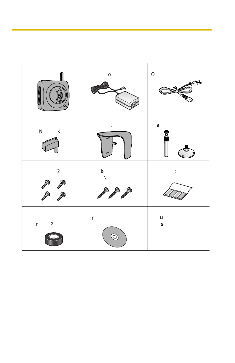
1.2 Included Accessories
The follo wing items are provided wit h the camera. Additional pieces can be order ed
by calling 1-800-332-5368.
Main Unit—1 pc. AC Cord—1 pc.
Connector Cover
—1 pc.
Order No.: PSKV1052Z1
Screws—4 pcs.
Order No.: XTN26+10GVW
Self Bonding tape
—1 pc.
Order No.: PSHG1235Z
AC Adaptor—1 pc.
Order No.: PQLV202W
Sunshade—1 pc.
Order No.:
Screws for
Flexible Stand—3 pcs.
Order No.: PQHE5004Z
Setup CD-ROM—1 pc.
Order No.: PSQX3242ZCD
PSKV1051Z1
Order No.: PSJA1069Z
Stand A (Left)—1 pc.
Stand B (Right)—1 pc.
Putties—1 set (4 pcs.)
Order No.: PSHG1259Z
Installation/
Troubleshooting
(This manual)—1 pc.
[For assistance, please call: 1-800-272-7033] 11
Installation/Troubleshooting
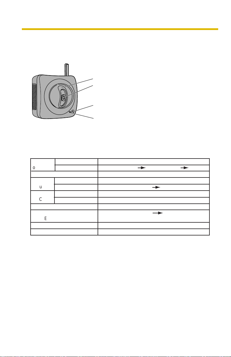
1.3 Camera Feature Locations
1.3.1 Front View
Lens Cover
Lens (0.5 m [about 20 inches]—Unlimited )
Indicator
The indicat or color shows camera status.
Microphone
The microphone picks up audio around the camera.
(See page 29 of the Operating Instructions on the
Setup CD-ROM)
Indicator Display
Power
on
Automatic
Setup
Using
DHCP
DEFAULT RESET button
Not on the LAN
Normal Operation*
Updating Firmware
Pressing FACTORY
On the LAN
Finished setting
Getting IP address*
Got IP address
TM
Failure Orange blinking (About a 2-second interval)
UPnP
Internal Failure Red blinking*
1
Setting
Orange blinking Green
2
Orange blinking
Green blinking
Green blinking
Green blinking
Orange blinking
Orange blinking Turning off
(The camera restarts after that.)
Green blinking
Green
Green
Green
3
12
*1 The indicator turns orange if the camera is not connected to the LAN.
*2 The indicator blinks orange if the camera is not connected to the LAN.
3
See page 48.
*

1.3.2 Side View
1.3.3 Bottom View
Installation/Troubleshooting
RESTART Button
Restarts the camera.
(see page 129 of the Operating
Instructions on the Setup CD-ROM).
SD Memory Card Slot
(See page 38)
FACTORY DEFAULT RESET Button
Resets settings to default (see page
128 of the Operating Instructions on
the Setup CD-ROM).
Stand/Tripod Mounting Hole (See page 43 and page 45)
[For assistance, please call: 1-800-272-7033] 13
Installation/Troubleshooting
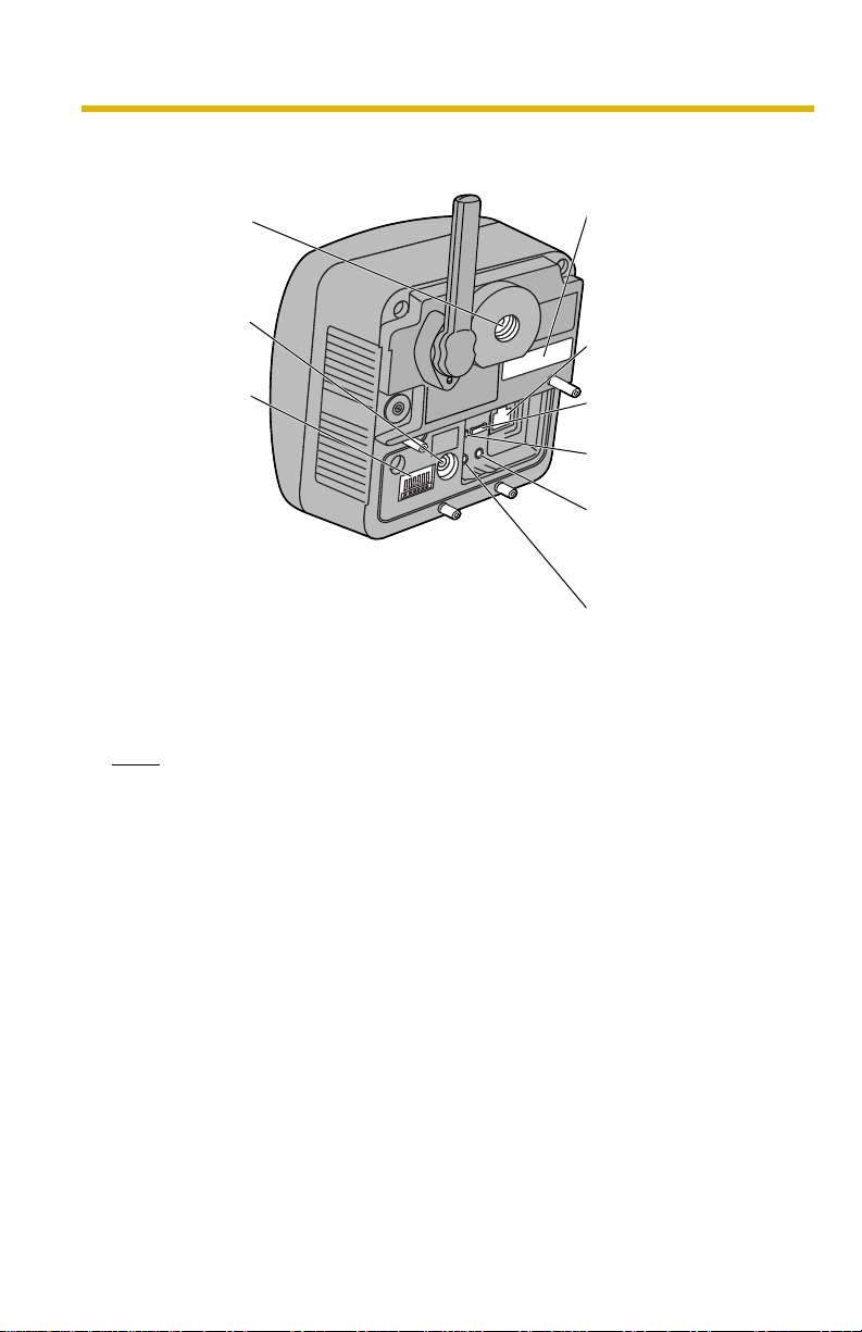
1.3.4 Rear View
Stand
Mounting Hole
(See page 44)
MAC Address (see page
18) and Serial number (S/
N) is indicated on the
label.
DC IN jack
(See page 16)
Ethernet
®
(LAN) port
(See page 15)
External I/O
(See page 126
of the
Operating
Instructions on
the Setup CD-
ROM))
Hook for Audio Cables
(See page 41)
Hook for Power Cord
(See page 41)
Audio Output Terminal
(See page 30 of the
Operating Instructions on
the Setup CD-ROM)
External Microphone
Input Terminal
(See page 30 of the
Operating Instructions on
the Setup CD-ROM)
Note
To listen to audio from the camera, an external amplified speaker (customerprovided) must be connected to the camera. The connector used is a stereo
type, similar to that used by amplified PC speakers. Though the connector is
stereo, the aud io is not .
14
Installation/Troubleshooting
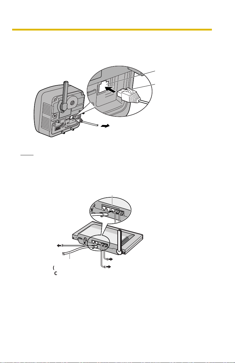
1.4 Connecting the Camera to Yo ur Router
Connect the camera to your router with an Ethernet cable to set up the camera.
1. Connect the Ethernet cable (customer-provided) to the camera.
Ethernet port
Ethernet cable
To your router
Note
These instructions assume your PC is already connected to the Internet and
your network includes a router.
2. Connect the Ethernet cable to your router.
To a LAN port of your router
To your modem
Ethernet cable
(Straight Cat5 cable)
(Customer-provided)
To your PC
To the outlet
[For assistance, please call: 1-800-272-7033] 15
Installation/Troubleshooting
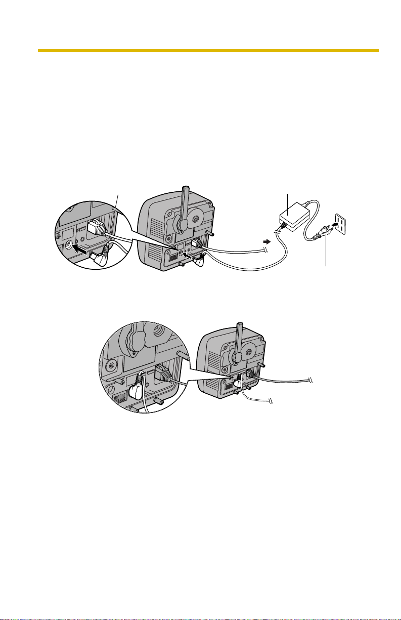
3. Connect the AC ada ptor cord to the D C In jack , and plug the AC cord into the
outlet.
• The AC cord is used as the main disconnect device, ensure that the
socket-outlet is located/instal led near the equipment and is easily
accessible.
• Use only specified Panasonic AC adaptor PQLV202 (Order No.
PQLV202W).
• If the indicator does not light green, see page 47 and page 48.
• A noise can be heard during pan/tilt operation. This is normal.
AC adaptor cord
To Router
AC adaptor
4. Hook the AC adaptor cord to the Hook for Power Cord.
AC cord
16
Installation/Troubleshooting
1.5 Setting up the Camera to View on the LAN
Setup CD-ROM allows you to easily set up the camera.
Notes
• To avoid any possible problems, temporarily disable any firewall or
antivirus softwa re.
• This procedure explains installation of the camera on the same network
that your PC is part of.
• Before proceeding, close your web browser.
• See page 140 of the Operating Instructions on the Setup CD-ROM for
details.
• To set the Wireless Configuration, the wireless LAN settings of your
router—SSID, communication mode and encryption etc.—are required.
(See your wireless router's manu al f or your referen ce to the wireless LAN
settings.)
• When there are some came ras or PCs that are comm unicating wireless ly ,
the IP addresses may overlaps and the camera may not be able to
communicate . See page " " of the Oper ating Instructions on the Setup CDROM.
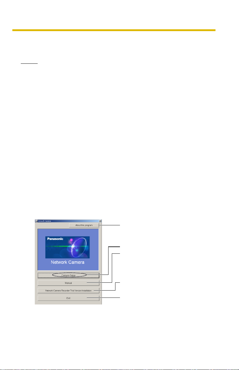
1. Insert the Setup CD-ROM into the CD-ROM drive of the PC.
• The window is automatically displayed.
(If the Network Camera Setup window is not displayed automatically,
double-click "Setup.exe" file on the Setup CD-ROM.)
2. Click [Camera Setup].
Displays version information
about this program.
Sets up the camera.
Displays the camera manuals.
If your PC does not ha v e Adobe®
Acrobat
the Adobe Reader website.
Installs Network Camera
Recorder trial version.
Closes the Setup Program.
[For assistance, please call: 1-800-272-7033] 17
®
Reader®, install it from
Installation/Troubleshooting
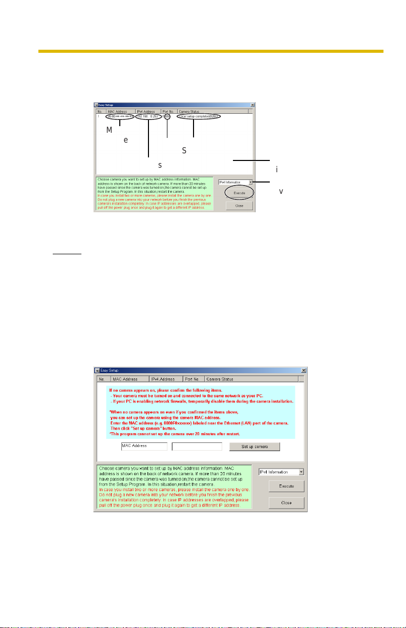
3. Select the camera to set up and click [Execute].
• This program searches for the cameras that are connected to the router
and displays the MAC Addresses, IP addresses and Por t Numbers.
MAC
Address
IP
Address
• The MAC Address on the rear side (see page 14) of the camera shows
which camera you select on the Camera List window.
Notes
• If more than 20 minu tes have passed since the camera w as turned on, the
camera cannot be set up from the Setup Program. In this situation,
disconnect the AC cord from the outlet, and reconnect it again.
• The Setup Program may not list any cameras due to your firewall or
antivirus software settings on your PC. If you cannot disable y our firewall
or antivirus software , you can set up the camera entering the c amera MAC
address on the following window. The camera's MAC address can be
found on the label affixed to the back of each camera. See page 32 for
details.
Port
No.
Camera
Status
Camera
List window
Displays IPv4 or
IPv6 information.
18
Installation/Troubleshooting
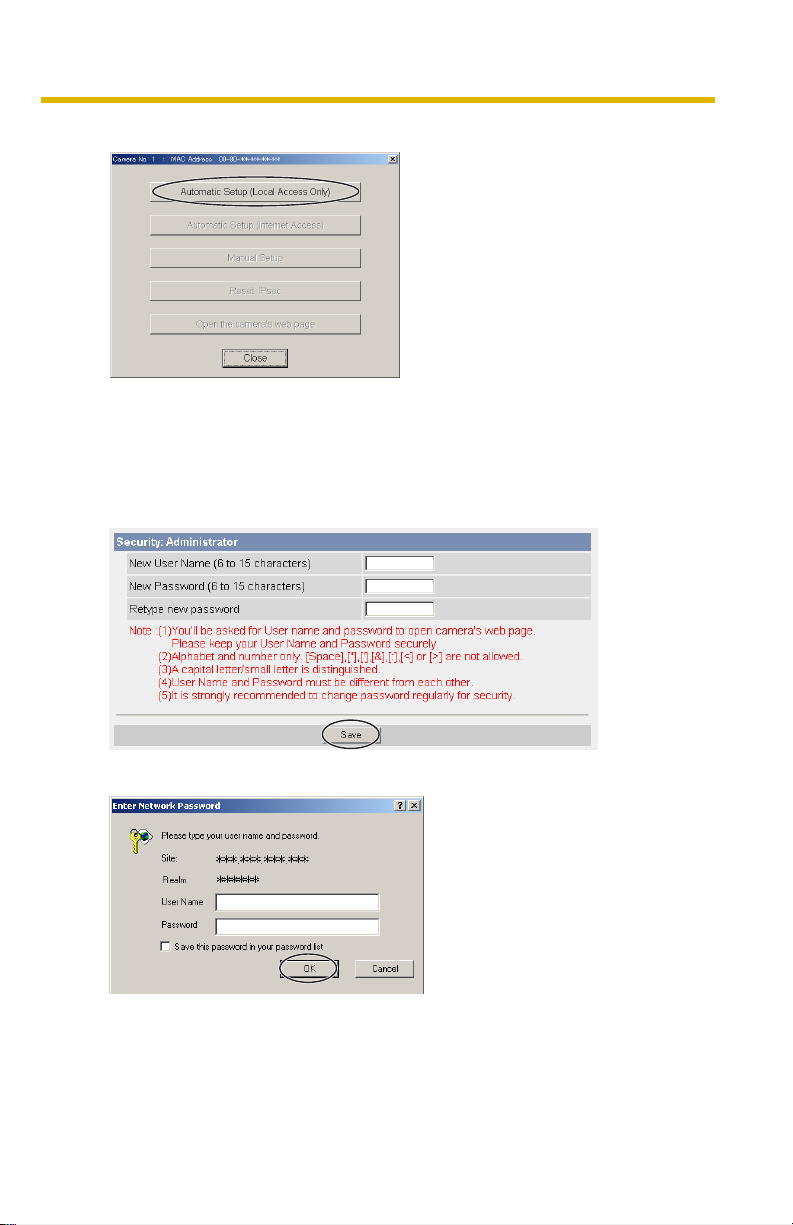
4. Click [Automatic Setup (Local Access Only)].
• For the first time installation or after pressing the FACTORY DEFAULT
RESET button, only [Automatic Setup (Local Access Only)] can be
selected. To set up the camera with Static or DHCP settings, after
performing the [Automatic Setup (Local Access Only)], run the Setup
Program again and select [Manual Setup].
5. Enter the user name and password you wish to use, and click [Save].
6. Enter the name and password that were entered above, and click [OK].
[For assistance, please call: 1-800-272-7033] 19
Installation/Troubleshooting
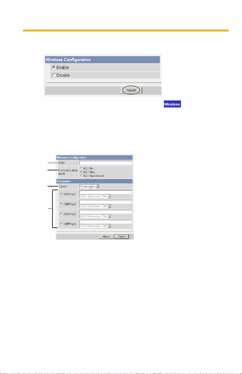
7. To set the Wireless Configuration, check [Enable] and click [Next>].
• When [Disable] was selected, skip to step 9.
• The Wireless Configur a t io n c an a lso be set at in the Setup Page .
(See page "" of the Operating Instructions in the Setup CD-ROM.)
8. Set the Wireless Confi gura tion a ccord ing to the wireles s s ettings o f the rou ter
and click [Ne xt>].
• For more information about wireless setting, see
http://panasonic.co.jp/pcc/products/en/netwkcam/technic/wireless/
cam_set.html
1
2
3
20
4
1. Set the SSID.
Set the name of the wireless network.
2. Select the Communication mode.
They are IEEE Communication modes. Select the same Communication
mode as that of the router to which the camera is connected.
802.11b (IEEE802.11b) : Only 802.11b wireless router can
be connected.
802.11b/g (IEEE802.11g) : Either 802.11b or 802.11g router
can be connected.
802.11g exclusive
(IEEE802.11g)
: Only 802.11g router can be
connected.
 Loading...