

Page 1
ORDER NO. VRD9802005C2
Video Cassette Recorder
Panasonicml
Z-MECHANISMCHASSIS
I
INTRODUCTION
The Z-Mechanism chassis are built in several Panasonic VHS Video Cassette
Recordersfrom NV-SD and NV-HD series in 1998.
WARNING
A
This service information isdesigned for experienced repair technicians only and is not designed for use by the general public. It does not contain
warnings or cautions to advise non-technical individuals of potential dangers in attempting to service a product.
Products powered by electricity should be serviced or repaired only by experienced professional technicians. Any attempt to service or repair the
IJroductor
Dt’OdUCtSdealt with in this service information by anyone else could result in serious injury or death.
.
(@1998 Matsushita Electric Industrial Co., Ltd.
All rights reserved. Unauthorized copying and
distribution is a violation of
law,
Panasonic
Page 2
CONTENTS
1.
OUTLINE OF ZMECHANISM . . . . . . . . . . . . . . . . . . . . . . . . . . . . . . . . . . . . . . . . . . . . . . . . . . . . . . . . . . . . . . . . 1
1-1.
Thetapetransportpath . . . . . . . . . . . . . . . . . . . . . . . . . . . . . . . . . . . . . . . . . . . . . . . . . . . . . . . . . . . . . . . . 1
1-2.
Cassetteholderunit . . . . . . . . . . . . . . . . . . . . . . . . . . . . . . . . . . . . . . . . . . . . . . . . . . . . . . . . . . . . . . . . . . . 2
1-3.
1-4.
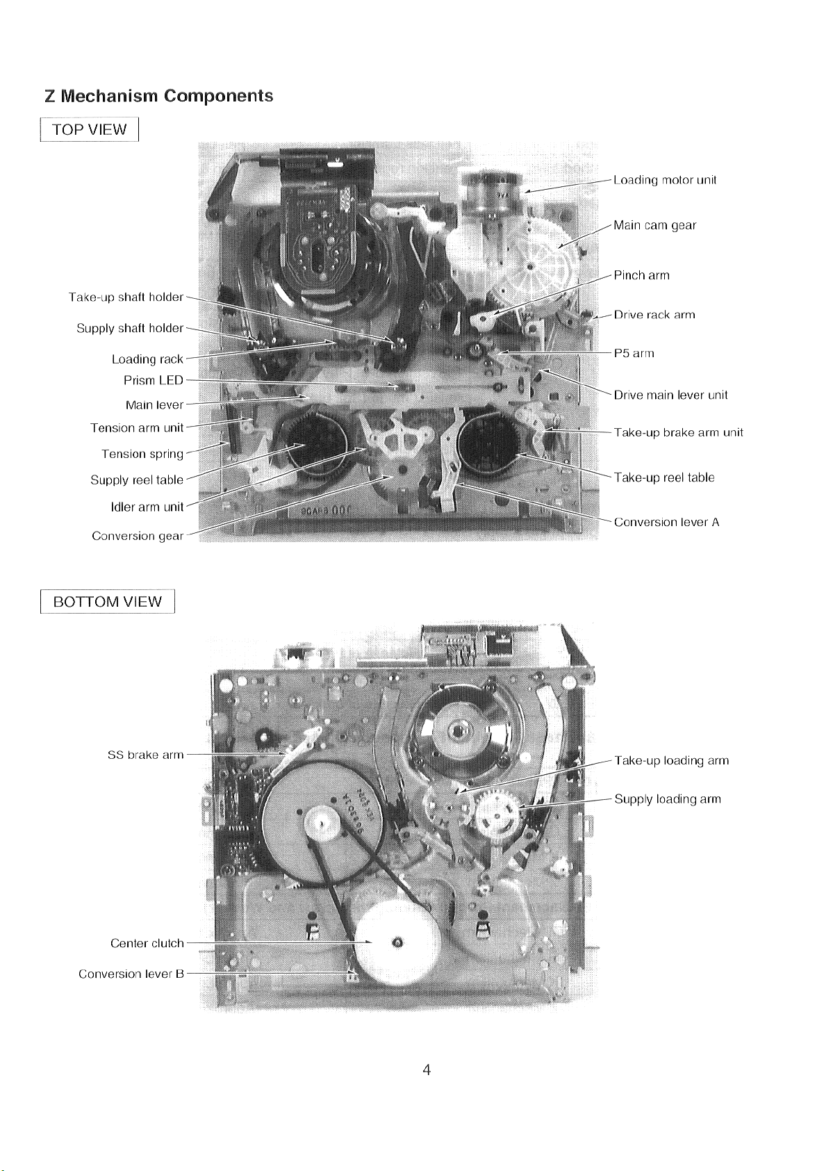
ZMechanismComponents . . . . . . . . . . . . . . . . . . . . . . . . . . . . . . . . . . . . . . . . . . . . . . . . . . . . . . . . . . . . . . . . . . . 4
FLOWCHARTOF LOADING MECHANISM . . . . . . . . . . . . . . . . . . . . . . . . . . . . . . . . . . . . . . . . . . . . . . . . . . . . . 5
REMOVALOFCASSEITETAPE . . . . . . . . . . . . . . . . . . . . . . . . . . . . . . . . . . . . . . . . . . . . . . . . . . . . . . . . . . . . . 6
2.
2-1. Removalofcompulsoryloading . . . . . . . . . . . . . . . . . . . . . . . . . . . . . . . . . . . . . . . . . . . . . . . . . . . . . . . . . . 6
2-2. Removalofmanual operation ofMaincam gear . . . . . . . . . . . . . . . . . . . . . . . . . . . . . . . . . . . . . . . . . . . . . 6
REMOVALOFCASSETTE HOLDER UNIT& MECHANISM Chassis . . . . . . . . . . . . . . . . . . . . . . . . . . . . . . . . 7
3,
3-1. Removal ofCassetteholder unit . . . . . . . . . . . . . . . . . . . . . . . . . . . . . . . . . . . . . . . . . . . . . . . . . . . . . . . . . 7
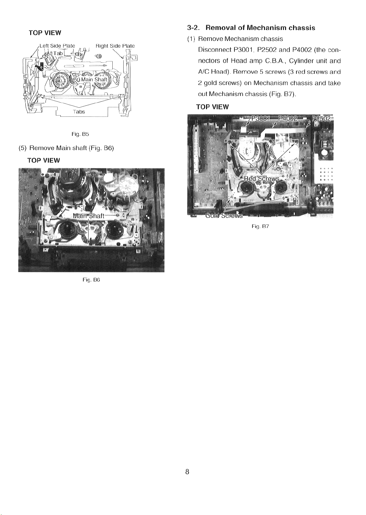
3-2. RemovalofMechanismchassis . . . . . . . . . . . . . . . . . . . . . . . . . . . . . . . . . . . . . . . . . . . . . . . . . . . . . . . . . . 8
DISASSEMBLY/ASSEMBLYMETHOD FORMECHANISM . . . . . . . . . . . . . . . . . . . . . . . . . . . . . . . . . . . . . . . . . 9
4.
4-1. Disassemblyofmechanism . . . . . . . . . . . . . . . . . . . . . . . . . . . . . . . . . . . . . . . . . . . . . . . . . . . . . . . . . . . . . 9
4-2. Assemblyandphaseadjustment ofmechanism . . . . . . . . . . . . . . . . . . . . . . . . . . . . . . . . . . . . . . . . . . . . . 14
4-3. Assemblyofmechanismchassis . . . . . . . . . . . . . . . . . . . . . . . . . . . . . . . . . . . . . . . . . . . . . . . . . . . . . . . . . 20
PartsAccess Flowchart . . . . . . . . . . . . . . . . . . . . . . . . . . . . . . . . . . . . . . . . . . . . . . . . . . . . . . . . . . . . . . . . . . . . 23
MECHANICALADJUSTMENT PROCEDURES . . . . . . . . . . . . . . . . . . . . . . . . . . . . . . . . . . . . . . . . . . . . . . . . . . 24
5.
5-1. Tension postposition adjustment . . . . . . . . . . . . . . . . . . . . . . . . . . . . . . . . . . . . . . . . . . . . . . . . . . . . . . . . 24
5-2. Backtensionadjustment . . . . . . . . . . . . . . . . . . . . . . . . . . . . . . . . . . . . . . . . . . . . . . . . . . . . . . . . . . . . . . . 24
5-3.
5-4. Tapeinterchangeabilityadjustment . . . . . . . . . . . . . . . . . . . . . . . . . . . . . . . . . . . . . . . . . . . . . . . . . . . . . . . 25
Servicing Fixtures&Tools . . . . . . . . . . . . . . . . . . . . . . . . . . . . . . . . . . . . . . . . . . . . . . . . . . . . . . . . . . . . . . . . . . . 30
6.
SELF-TESTINDICATION DISPLAY . . . . . . . . . . . . . . . . . . . . . . . . . . . . . . . . . . . . . . . . . . . . . . . . . . . . . . . . . . . 31
SERVICE INFORMATION DISPLAY . . . . . . . . . . . . . . . . . . . . . . . . . . . . . . . . . . . . . . . . . . . . . . . . . . . . . . . . . . . 33
7.
7-1.
7-2. TurningonService information Display . . . . . . . . . . . . . . . . . . . . . . . . . . . . . . . . . . . . . . . . . . . . . . . . . . . . 33
7-3.
7-4.
7-5.
7-6. Timingchartfrom ModeSWto Systemcontrol lo . . . . . . . . . . . . . . . . . . . . . . . . . . . . . . . . . . . . . . . . . . . . 38
SYSTEM CONTROLCIRCUIT &MECHANISM CONTROLCIRCUIT . . . . . . . . . . . . . . . . . . . . . . . . . . . . . . . . . 39
8.
8-1. STOP3Specification . . . . . . . . . . . . . . . . . . . . . . . . . . . . . . . . . . . . . . . . . . . . . . . . . . . . . . . . . . . . . . . . . . 39
8-2.
8-3. SupplyandTake-upSensors . . . . . . . . . . . . . . . . . . . . . . . . . . . . . . . . . . . . . . . . . . . . . . . . . . . . . . . . . . . 40
8-4. SafetyTabSwitch . . . . . . . . . . . . . . . . . . . . . . . . . . . . . . . . . . . . . . . . . . . . . . . . . . . . . . . . . . . . . . . . . . . . 40
8-5. DewSensor . . . . . . . . . . . . . . . . . . . . . . . . . . . . . . . . . . . . . . . . . . . . . . . . . . . . . . . . . . . . . . . . . . . . . . . . . 41
8-6. Settingtimeforeach mode . . . . . . . . . . . . . . . . . . . . . . . . . . . . . . . . . . . . . . . . . . . . . . . . . . . . . . . . . . . . . 42
8-7. OperationofshortCUE . . . . . . . . . . . . . . . . . . . . . . . . . . . . . . . . . . . . . . . . . . . . . . . . . . . . . . . . . . . . . . . . 42
8-8. Loading/Unloading Mechanism lock . . . . . . . . . . . . . . . . . . . . . . . . . . . . . . . . . . . . . . . . . . . . . . . . . . . . . . 42
8-9. Cassetteloading/unloadinglock . . . . . . . . . . . . . . . . . . . . . . . . . . . . . . . . . . . . . . . . . . . . . . . . . . . . . . . . . 42
8-10. Reel lockoperation . . . . . . . . . . . . . . . . . . . . . . . . . . . . . . . . . . . . . . . . . . . . . . . . . . . . . . . . . . . . . . . . . . . 43
8-11. Cylinderlock . . . . . . . . . . . . . . . . . . . . . . . . . . . . . . . . . . . . . . . . . . . . . . . . . . . . . . . . . . . . . . . . . . . . . . . . 43
8-12. Modetransition . . . . . . . . . . . . . . . . . . . . . . . . . . . . . . . . . . . . . . . . . . . . . . . . . . . . . . . . . . . . . . . . . . . . . . 44
8-13. Poweron reset . . . . . . . . . . . . . . . . . . . . . . . . . . . . . . . . . . . . . . . . . . . . . . . . . . . . . . . . . . . . . . . . . . . . . . . 44
8-14. Lineartimecounteroperation . . . . . . . . . . . . . . . . . . . . . . . . . . . . . . . . . . . . . . . . . . . . . . . . . . . . . . . . . . . 44
8-15. Tapespeed inCUE/REVmode . . . . . . . . . . . . . . . . . . . . . . . . . . . . . . . . . . . . . . . . . . . . . . . . . . . . . . . . . . 45
8-16. Automaticfunctions . . . . . . . . . . . . . . . . . . . . . . . . . . . . . . . . . . . . . . . . . . . . . . . . . . . . . . . . . . . . . . . . . . . 45
8-17. CUE/REVlockmode . . . . . . . . . . . . . . . . . . . . . . . . . . . . . . . . . . . . . . . . . . . . . . . . . . . . . . . . . . . . . . . . . . 45
8-18. FR(Forward/Reverse) search mode . . . . . . . . . . . . . . . . . . . . . . . . . . . . . . . . . . . . . . . . . . . . . . . . . . . . . . 45
8-19. FF/REWspeed . . . . . . . . . . . . . . . . . . . . . . . . . . . . . . . . . . . . . . . . . . . . . . . . . . . . . . . . . . . . . . . . . . . . . . 45
8-20. FF/REWtime . . . . . . . . . . . . . . . . . . . . . . . . . . . . . . . . . . . . . . . . . . . . . . . . . . . . . . . . . . . . . . . . . . . . . . . . 45
EXPLODEDVIEWS &REPLACEMENT PARTS LIST
9.
9-1. MECHANICAL REPLACEMENT PARTS SECTION
Reel brake . . . . . . . . . . . . . . . . . . . . . . . . . . . . . . . . . . . . . . . . . . . . . . . . . . . . . . . . . . . . . . . . . . . . . . . . . . 2
NumberofGearPhaseAlignment Pointand Replacement Parts . . . . . . . . . . . . . . . . . . . . . . . . . . . . . . . . 3
P2and P3postsadjustment . . . . . . . . . . . . . . . . . . . . . . . . . . . . . . . . . . . . . . . . . . . . . . . . . . . . . . . . . . . . 25
5-4-(I). P2ANDP3 POSTSADJUSTMENT . . . . . . . . . . . . . . . . . . . . . . . . . . . . . . . . . . . . . . . . . . . . . . . . 26
5-4-(2). ADJUSTMENTOFP4 POST . . . . . . . . . . . . . . . . . . . . . . . . . . . . . . . . . . . . . . . . . . . . . . . . . . . . . 27
5-4-(3). HEIGHTADJUSTMENT OFA/C HEAD . . . . . . . . . . . . . . . . . . . . . . . . . . . . . . . . . . . . . . . . . . . . . 28
5-4-(4). FINE-ADJUSTMENTOF A/CHEAD . . . . . . . . . . . . . . . . . . . . . . . . . . . . . . . . . . . . . . . . . . . . . . . 28
5-4-(5). ADJUSTMENTOFX-VALUE . . . . . . . . . . . . . . . . . . . . . . . . . . . . . . . . . . . . . . . . . . . . . . . . . . . . . 28
5-4-(6). FINE-ADJUSTMENT OFX-VALUE . . . . . . . . . . . . . . . . . . . . . . . . . . . . . . . . . . . . . . . . . . . . . . . . 29
PurposeofService information Display . . . . . . . . . . . . . . . . . . . . . . . . . . . . . . . . . . . . . . . . . . . . . . . . . . . . 33
UseofService Modes . . . . . . . . . . . . . . . . . . . . . . . . . . . . . . . . . . . . . . . . . . . . . . . . . . . . . . . . . . . . . . . . . 34
Service Information Number . . . . . . . . . . . . . . . . . . . . . . . . . . . . . . . . . . . . . . . . . . . . . . . . . . . . . . . . . . . . 36
TestMode . . . . . . . . . . . . . . . . . . . . . . . . . . . . . . . . . . . . . . . . . . . . . . . . . . . . . . . . . . . . . . . . . . . . . . . . . . 36
Stand-byintheSTOP3position . . . . . . . . . . . . . . . . . . . . . . . . . . . . . . . . . . . . . . . . . . . . . . . . . . . . . . . . . 39
Page 3
1. OUTLINEOFZ MECHANISM
‘2’os’Fv=R’3’osT
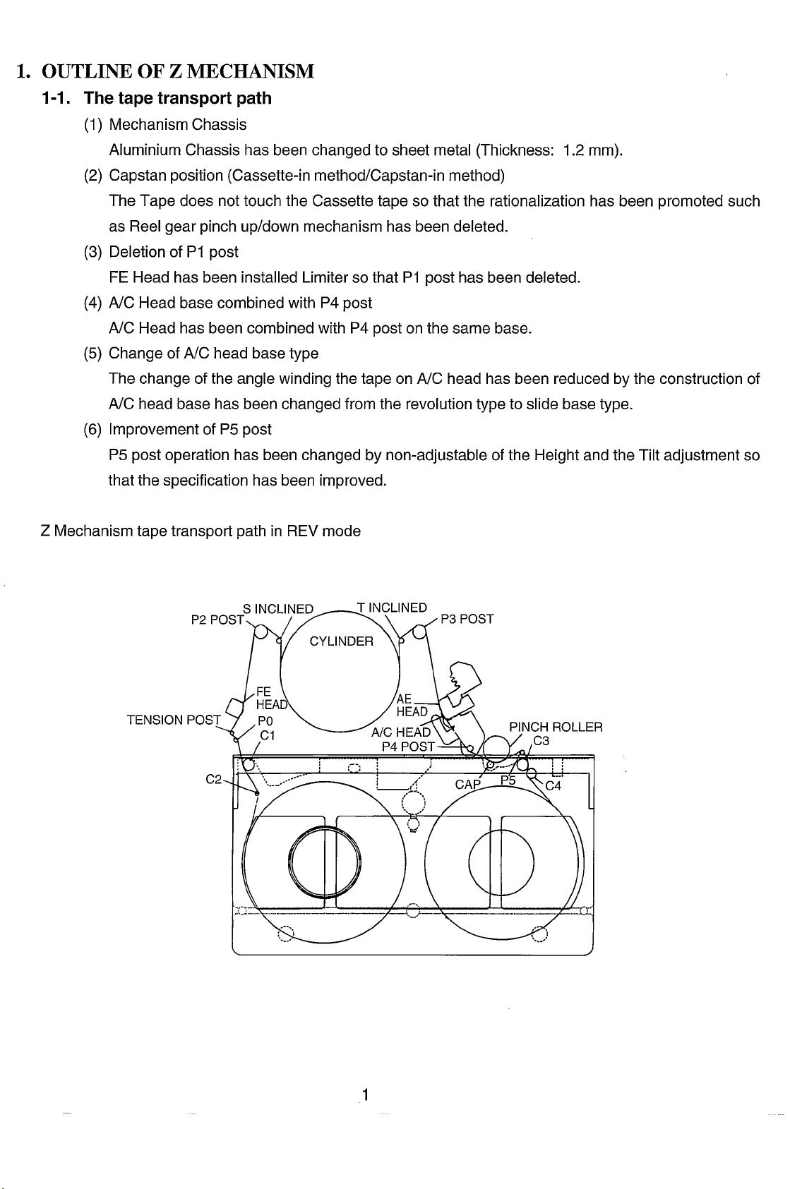
1-1. The tape transport path
(1)
Mechanism Chassis
Aluminium Chassis has been changed to sheet metal (Thickness: 1.2 mm).
(2)
Capstan position (Cassette-in method/Capstan-in method)
The Tape does not touch the Cassette tape so that the rationalization has been promoted such
as Reel gear pinch up/down mechanism has been deleted.
Deletion of PI post
(3)
FE Head has been installed Limiter so that PI post has been deleted.
(4)
A/C Head base combined with P4 post
A/C Head has been combined with P4 post on the same base.
Change of NC head base type
(5)
The change of the angle winding the tape on A/C head has been reduced by the construction of
A/C head base has been changed from the revolution type to slide base type.
Improvement of P5 post
(6)
P5 post operation has been changed by non-adjustable of the Height and the Tilt adjustment so
that the specification has been improved.
Z Mechanism tape transport path in REV mode
TENSION P“
Page 4
1-2. Cassette holder unit
(1)Cassette-in operation
The Rackdrive arm drives Main Cam gear by inserting the cassette tape. Consequently, Position
switch detects the cassette-in mode so that Loading motor drives. The mode goes to the Stop
mode from the Cassette-in through the Loading mode.
@) The parts quantity reduction of Cassette holder unit.
(Z Mechanism: 21 pieces, K Mechanism: 36 pieces)
a. Release lever has been installed in Right Side Plate.
b. Cassette guide has been installed in Front Panel unit.
c. Safety lever spring is made by the resin.
d. Opener lever has been changed into the single opener type.
e. One side of Side Plate unit is hung on Chassis in order to fix it.
@ Improvement of the cassette insertion
(The force ofthe cassette insertion Z Mechanism: Approximately 400gm.,
The tooth pitchof Worm gearwhich hasbeen extended against the previous model, is located
on the Motor so that Worm gear can be reversed. Consequently, the Motor rotates before the
K Mechanism: Approximately 600gm.)
1-3.
insertion spring (the combined spring) is working when the cassette tape is inserted, so that
the repelled force of the insertion spring has been reduced as differing from the present
model.
@ Small-sized Cassette holder unit (Thinned unit)
a. The Wiper arm method which has been adopted, assigned Wiper arm between Cassette
Holder Plate and Side Plate so that the small-sized of the width has been realized.
b. To prevent the increment of parts quantity such as Safety Iever is used for Pre-open
mechanism shown in the present model, and the small-sized unit has been realized by
inclining one portion of the Lgroove in Side Plate.
c. The part of driving change-over is located in the nearest to the center of Reel so that the
depth size is compacter.
Reel brake
(1)
Supply Reel Brake is used for Tension Regulator which is composed of the conventional Main
brake and the soft brake function.
Take-up Reel Brake is used as Band Brake unit in order to correspond with Supply Reel
(2)
Tension Regulator performance:
x
This is composed of Tension regulator and brake. The tape always is given the tension
Brake.
against
the advance direction by Tension band.
Construction of Supply reel tension regulator
(3)
Comparison ofthe construction with the conventional model
2
Page 5
I
Z Mechanism
K Mechanism
Tension Arm Shaft
Bearing construction
Tension Band
Braking method
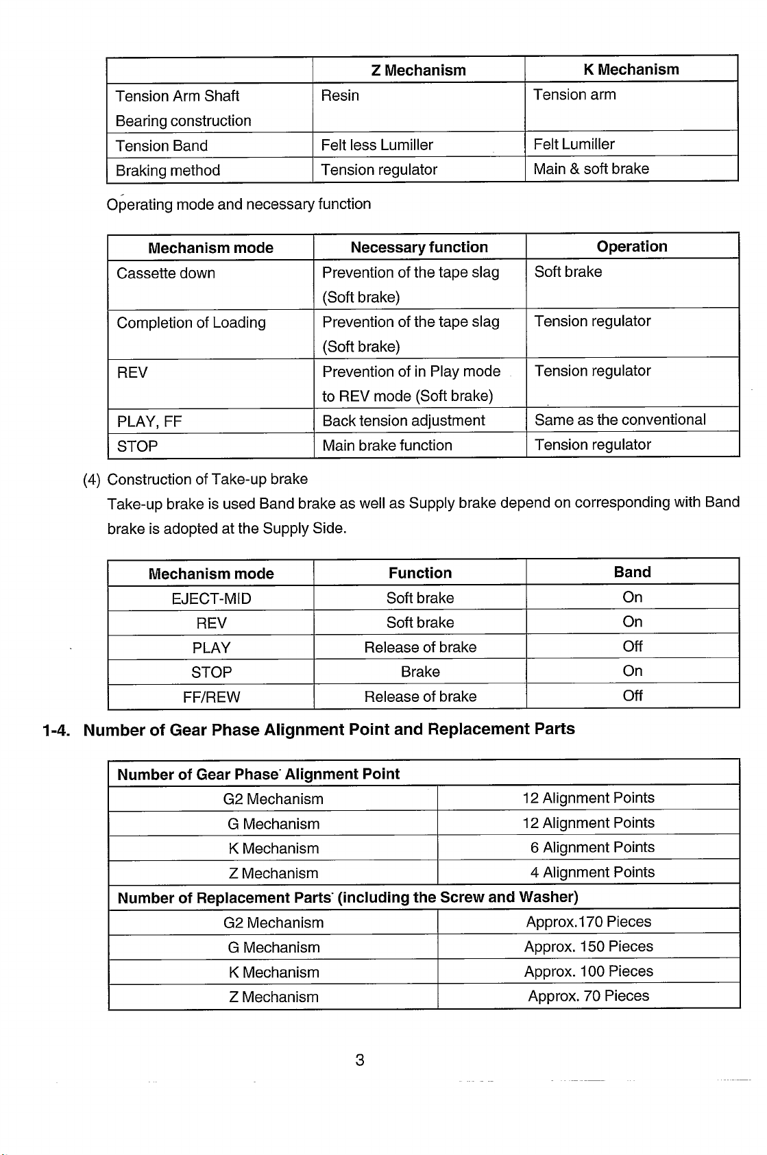
Operating mode and necessary function
Mechanismmode
Cassette down
Completion of Loading
REV
PLAY. FF
STOP
(4)
Construction of Take-up brake
Resin
Felt less Lumiller
Tension regulator
I Necessary function
Prevention of the tape slag
(Soft brake)
Prevention of the tape slag
(Soft brake)
Prevention of in Play mode
to REV mode (Soft brake)
Backtension adjustment
Main brake function
Tension arm
Felt Lumiller
Main & soft brake
Operation
Soft brake
Tension regulator
Tension regulator
Same as the conventional
Tension regulator
Take-up brake is used Band brake as well as Supply brake depend on corresponding with Band
brake is adopted at the Supply Side.
Mechanism mode
EJECT-MID
REV
PLAY
STOP
FF/REW
1-4. Number of Gear Phase Alignment Point and Replacement Parts
Number of Gear Phase-Alignment Point
G2 Mechanism
G Mechanism
K Mechanism
Z Mechanism
Number of Replacement Parts”(including the Screw and Washer)
Function
Soft brake
Soft brake
Release of brake
Brake
Release of brake
12Alignment Points
12Alignment Points
6 Alignment Points
4 Alignment Points
Band
On
On
off
On
off
G2 Mechanism
G Mechanism
K Mechanism
Z Mechanism
I
3
Approx.170 Pieces
Approx. 150 Pieces
Approx. 100 Pieces
Approx. 70 Pieces
Page 6
Page 7
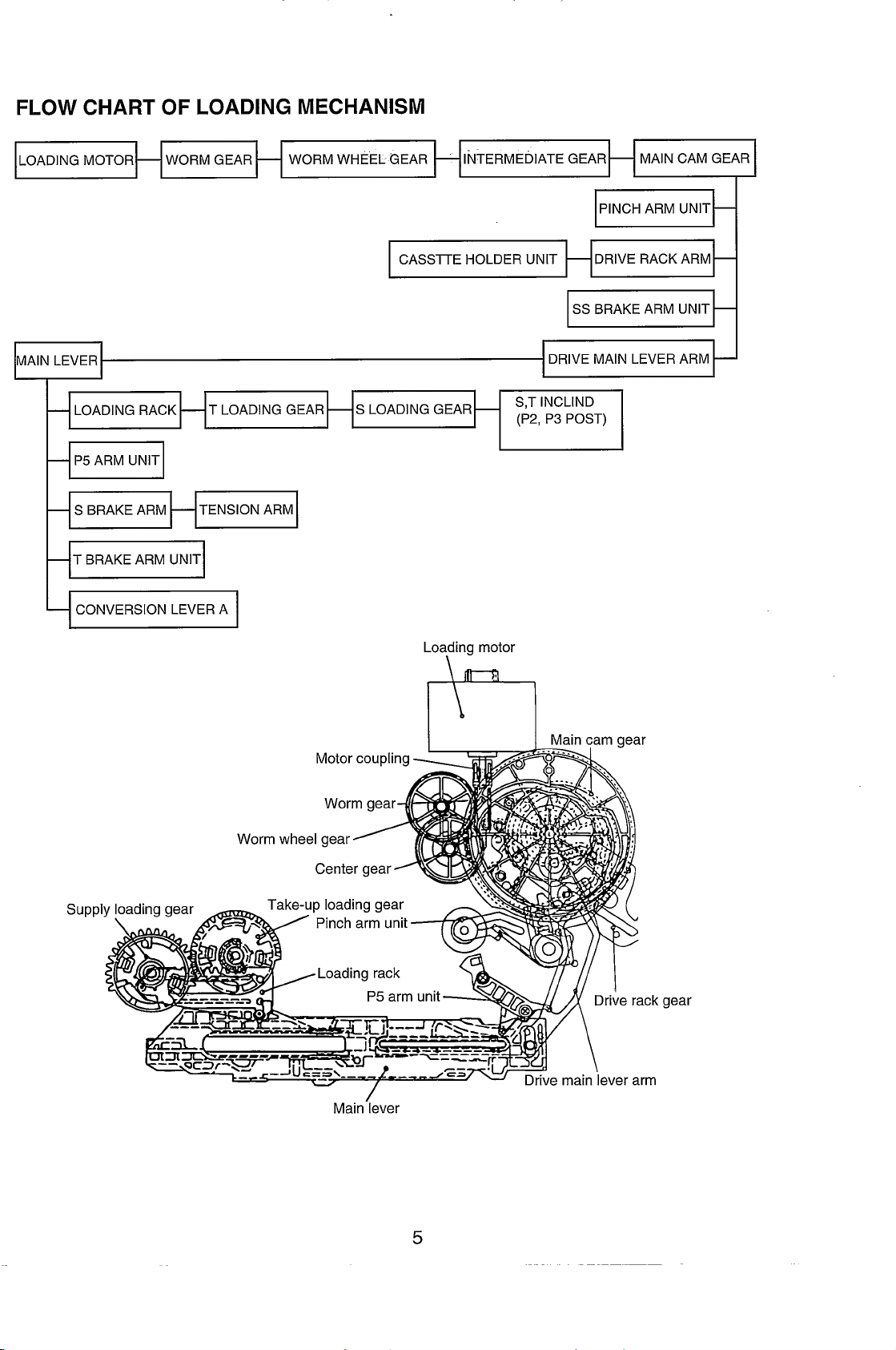
FLOW CHART OF LOADING MECHANISM
LOADING MOTOR
MAIN LEVER
I
l+TBRAKEARM UNITI
+ CONVERSION LEVERA I
T LOADING GEAR
CASSITE HOLDER UNIT
S LOADING GEAR
SS BRAKE ARM UNIT
S,T INCLIND
(P2, P3 POST)
MAIN CAM GEAR
PINCH ARM UNIT
DRIVE RACK ARM
—
—
—
Supplv
Inadinn mmr
Motorcoupling
Wormgear
Wormwheelgear
A
Centergear
Take-uploadinggear
\ Pincharmunit
\
,Loading rack
T
—.
Main-lever
Loafingmotor
Y
P,armunit-n
,.
,, w
..
...
b
...
/
gear
IT
5
Page 8

Page 9
Page 10
Page 11
Page 12
Page 13
Page 14
Page 15
Page 16

Page 17

Page 18

Page 19

Page 20

Page 21

Page 22

Page 23

Page 24

Page 25

1
—
I
U
u
>
u
z
G
2
—
—
—
—
m
@
P
m
cc
w
>
5
m
c1
q
Q
(u
—
23
Page 26

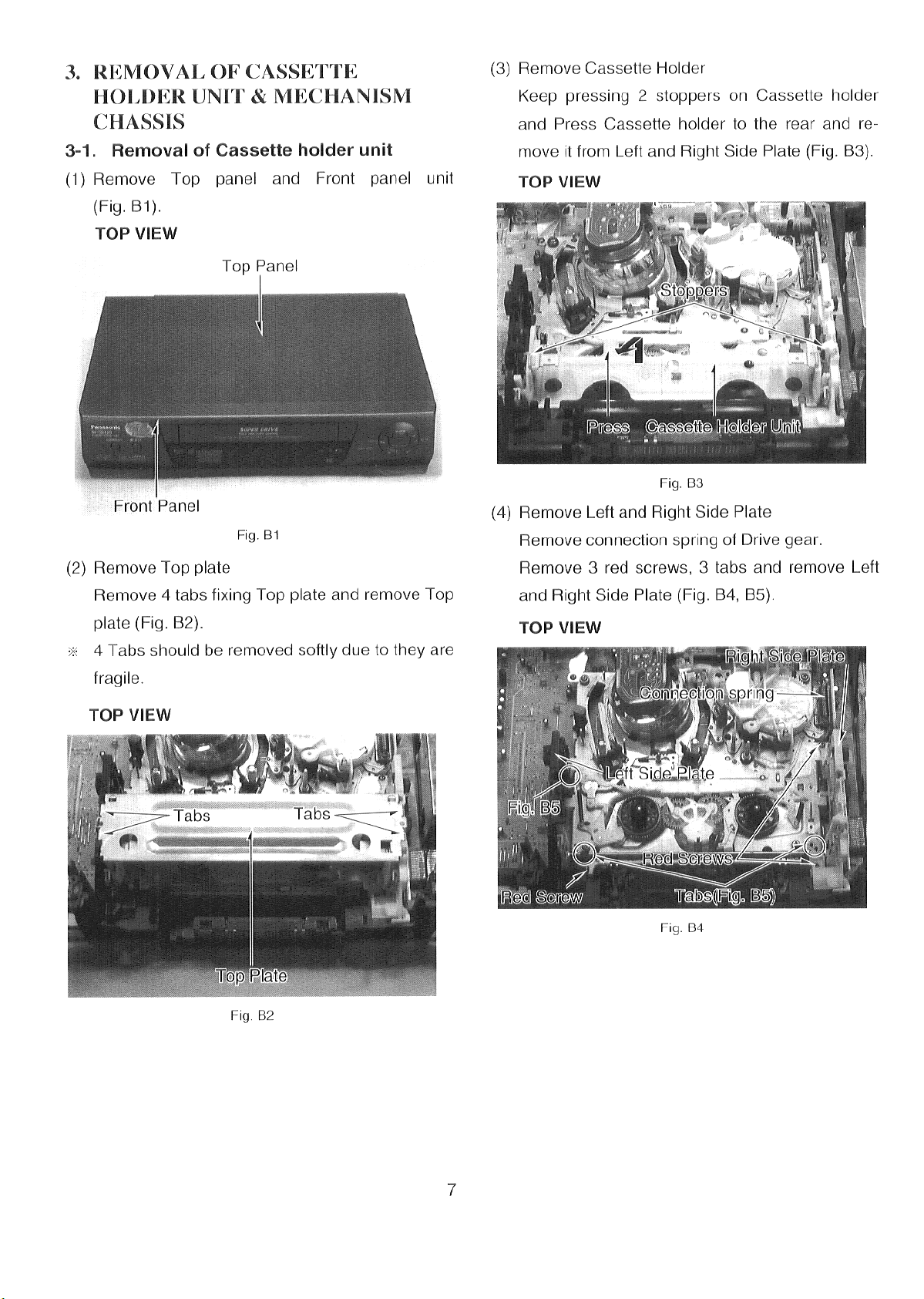
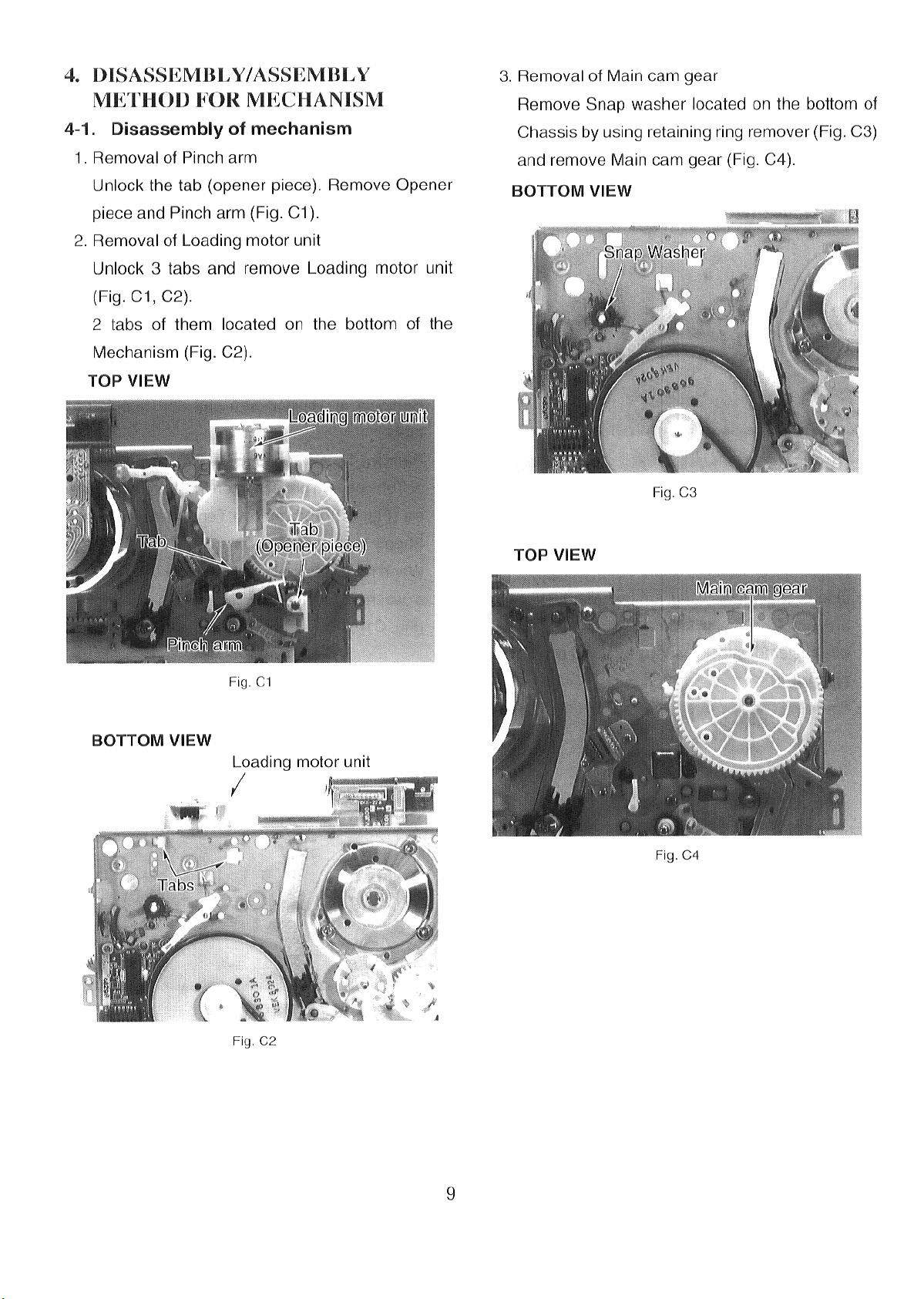
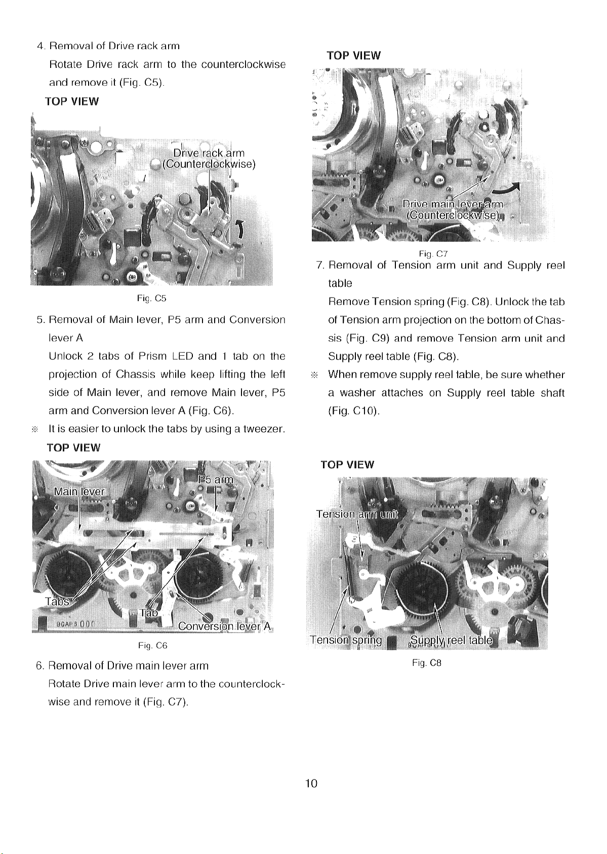
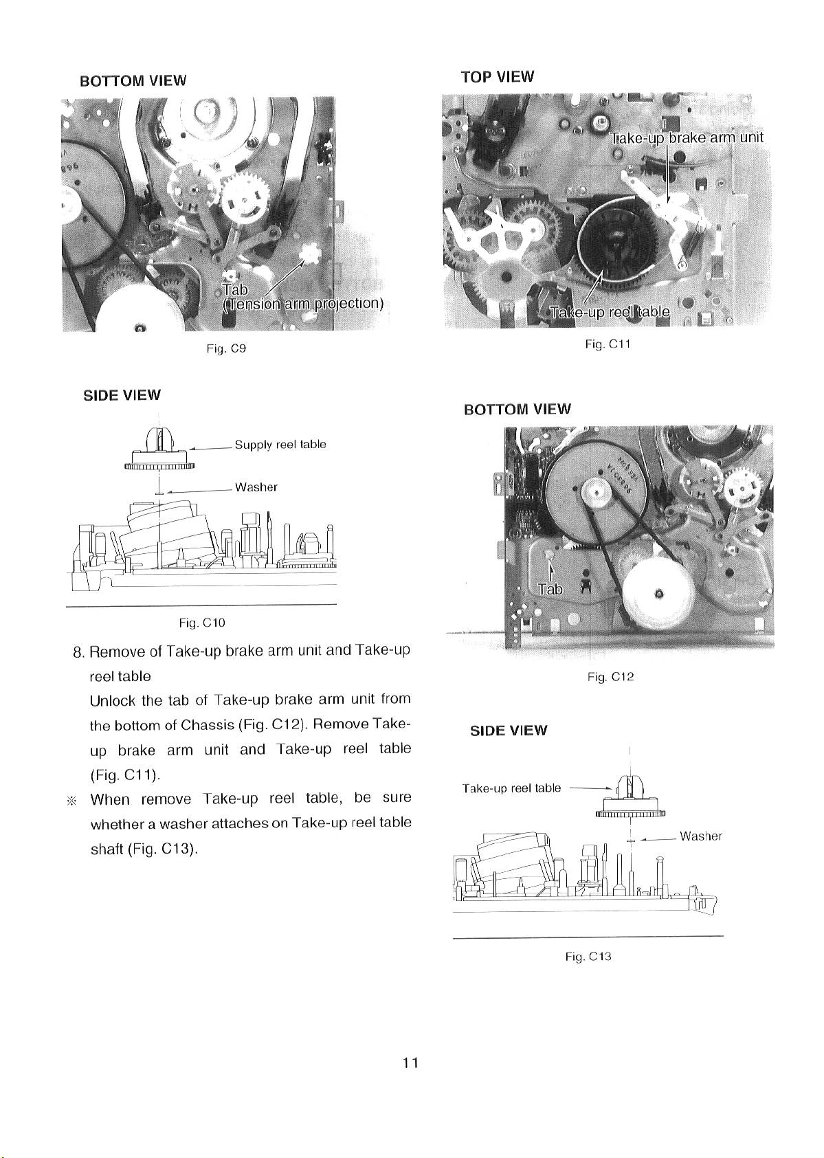
5. MECHANICAL ADJUSTMENT
PROCEDURE
5-1. Tension post position adjustment
Equipment required: Hex. Wrench (VFK0326)
Specification: 50.5* 1.5 mm
(1)
Disconnect the AC plug.
Remove the TOP PLATE.
(2)
Turn the LOADING MOTOR until the loading
(3)
completes.
Adjust the hole of Tension Band Fastener by Hex
(4)
Wrench until the distance between the Tension
Post and the center of Supply reel table is
50.5tl.5 mm as shown in Fig. Ml.
—
Playback the cassette tape from the beginning
(1)
and wait until the tape movement get the stabilization. (for approx. 10–20 seconds)
Insert the Back Tension Meter into the path of a
(2)
tape, and measure the back tension to be within
specification as shown in Fig. M2.
S Inclined post
S2 Post=..+
Probes of
Gauge
Tension
Post
\
<
50.5*1 .5mm
\
Fig. Ml
5-2.
Back tension adjustment
Equipment required:
Back Tension Meter (VFKOI32)
VHS Cassette tape (180 minutes tape: PAL)
table
Fig. M2
(3) If it is out of specification, change the spring
notch as shown in Fig. M3.
Tension spring
, Supply spring arm
“Springnotch
Fig. M3
VHS Cassettetape (120 minutes tape: NTSC)
Specification: 22.5–27.5g
24
Page 27

5-3.
P2 and P3 posts adjustment
(PREADJUSTMENT)
5-4. Tape interchangeability adjustment
Carry out the following procedures for Tape inter-
Equipment Required:
PostAdjustment Screwdriver (VFK0329)
(1) Remove the Top Plate.
(2) Turn the Loading Motor until the unloading com-
pletes.
(3) Rotatethe P2and P3 Posts clockwise to the end.
(Fig. M4)
(4) Rotate the P2 and P3 Posts twice counterclock-
wise. (Fig. M4)
c1
!!
1. Rotate the
POST clockwise
to the end
1
(5) Playback the cassette tape and make sure that
the edges of the tape are not curling at the bottom or top end of the P2, P3, and P4 Posts as
shown in Fig. M5.
2. Rotatethe
POST twice
counterclockwise
Fig. M4
changeability Adjustment to do it correctly and
smoothly.
P2 AND P3 POSTS ADJUSTMENT
(1)
(2)
ADJUSTMENT OF P4 POST
HEIGHT ADJUSTMENT OF WC HEAD
(3)
(4)
FINE-ADJUSTMENT OF A/C HEAD
ADJUSTMENT OF X-VALUE
(5)
(PREADJUSTMENT)
FINE-ADJUSTMENT OF X-VALUE
(6)
Ifthe Tape Interchangeability Adjustment is not per-
fect, repeat the above procedures from (1) to (6).
CAUTIONS: To make an Adjustment ModeforTape
Interchangeability, press the FF and
EJECT buttons simultaneously 3times
to set the Service Mode 2.
Incase of VCR mounted shuttle ring,turn the shuttle
ring to FF and then press EJECT button.
In Loewe model, STOP button is used instead of FF
button
NOTE Cleaning the Tape Transport pathbefore ad-
justing of Tape Interchangeability.The detail
portion is shown below.
POPost, Tension Posts, FE Head, P2 Post,
Supply Inclined Post, Cylinder Unit, Take-up
Inclined Post, P3 Post, A/C Head, P4 Post,
Post P2, P3 Post P4
Curling
/’
-Tape
-Tape
l!!
[No Good]
Fig. M5
(6) If the curling appears, readjusts the P2 and P3
Posts.
[Good]
25
I
Pinch Roller, Capstan Shaft, P5 Post. FE
Head, Cylinder Unit, A/C Head and Capstan
Shaft are more important parts and pay an
attention to clean them.
I
Page 28

5-4-(l). P2 AND P3 POSTS ADJUSTMENT
Equipment required:
Alignment Tape (PALLSECAM: VFJ8125H3F)
(NTSC: VFM8080HQFP)
PostAdjustment Screwdriver (VFK0329)
(2) Playbackthe Alignment Tape.
(3) If the RF envelope appears Iike example “A” or
“B” in Fig. M7, then adjustment of the tape guide
post (P2: Entrance) is necessary. e
(4) Adjust the tape guide post (P2) with the post
adjustment screwdriver so.that the RF envelope
(1) Connect. the oscilloscope to the output of the
Head Amp as shown in Fig. M6.
NOTE: To get a stable waveform of the Head Amp
output (observation point TW3001 and
TW2001 located on Main C.B.A.) on the oscilloscope, use the head switching pulse as
a triggering signal as shown in Fig. M6.
waveform at the entrance portion becomes flat
as shown in Fig. M7 “C”.
1
--------
I
Fig. M7
(5) If the RF envelope appears like “D” or “E” in
Fig. M8, then adjustment of the tape guide post
(P3: Exit) is necessary.
(6) Adjust the tape guide post (P3) in the same man-
Fig. M6 Connect of Oscilloscope
ner as the P2 post so that the exit portion becomes flat as shown in Fig. M8 “F”.
xit Portion
D
0.
E
F
I-
Fig. M8
26
Page 29

(7) Keep pressing the tracking up/down (A or v)
bu~ons on the remote controller unit. The output
envelope should vary nearly parallel with other
condition as shown in Fig. M9.
(8) Set the tracking control into center fix position by
pressing the tracking up/down
(A and v) simul-
taneously and adjust for maximum RF envelope,
whilst being as flat as possible.
Output envelope Mini.
~
+
I_
Output envelope Max.
(Fix position)
Good
Good
5-4-(2). ADJUSTMENT OF P4 POST
Install A/C Head on the Mechanism Chassis by
(1)
one screw.
Playback the Alignment Tape.
(2)
Rotate the screw (A) or (B) until the wrinkle ap-
(3)
pears on the lower edge of tape at P4 Post.
Rotate the screw (A) or (B) until the wrinkle just
(4)
disappears onthe lower edge of tape at P4 Post.
Connect the oscilloscope to audio output termi-
(5)
nal.
Rotate the screw (C) until audio signal is maxi-
(6)
mized.
NOTE: 1. The relation between the rotation direc-
tion of screws (A) and (B) and the condition of wrinkle on the lower edge at P4
Post as shown in Fig. Ml 1.
2. Make sure that there is not the inclined
wrinkle between P4 Post and Pinch
Roller.
Fig. M9
P2
Po
Fig. M1O Loading of Posts
So wrinkle
appears on the
lower edge of tape
So wrinkle
disappears on the
lower edge of tape
, ,
SCREW (A)
COUNTER
CLOCKWISE
CLOCKWISE :~#-&:sE
SCREW (B)
CLOCKWISE
1
I
27
Fig. Ml 1
Page 30

5-4-(3). HEIGHT ADJUSTMENT OF A/C
HEAD
<When moving the A/C Head up>
(1)
Rotate the screw (A) counterclockwise until the
wrinkle appears on the lower edge of tape at P4
Post.
Rotate the screw (B) counterclockwise until the
(2)
wrinkle just disappears onthe lower edge oftape
at P4 post.
Rotate the screw (C) counterclockwise until the
(3)
audio signal is maximized.
~
Q---(l)
5-4-(4). FINE-ADJUSTMENT OF A/C HEAD
Connect the oscilloscope to the output of the
(1)
Head Amp as shown in Fig. M6.
Playback the Alignment Tape.
(2)
Make sure that the condition of the wrinkle at P4
(3)
Post. If the condition of the wrinkle is out of
specification, P4 Post adjustment has to be performed as follows.
Turn the screw (A) counterclockwise until the
wrinkle appears on the lower edge of tape at P4
Post.
Turn the screw (A) clockwise until the wrinkle
disappears on the lower edge of tape at P4 Post.
Turn the screw (C) until the audio signal is maxi-
(4)
(2)- -@
%
c -----(3)
Q
<When moving the A/C Head down>
(1) Rotate the screw (B) clockwise until the wrinkle
appears on the lower edge of tape at P4 Post.
(2) Rotate the screw (A) clockwise until the wrinkle
just disappears on the lower edge of tape at P4
post.
(3) Rotate the screw (C) clockwise until the audio
signal is maximized.
P
Fig. M12
S (@ --(2)
mized.
NOTE: Make sure that the audio output does not
increase when push the upper and lower
I
5-4-(5).
edges of tape around A/C Head.
HeadAmp Output (RF Signal)
l-l
m
Fig. M14
ADJUSTMENT OF X-VALUE
. .
(PREADJUSTMENT)
u
t
Maximum
1
(l)- -@
c
G
G
Fig. M13
#
-----(3)
Equipment required:
Fine Adjustment Gear Drive (VFK0330)
Specification: Less than 15 msec.
(1) Connect the oscilloscope to the audio output and
the video output. Both output signals should be
fixed by the external trigger.
28
Page 31

(2) Playback the Alignment Tape and set the track-
ing control into center fix position.
(3) Adjust A/C Head position by the FineAdjustment
Gear Driver (VFK0330) to meet the signal fault
portion of the audio output and the video output
signals (Lessthan 15 msec.).
(4) After meeting the signal fault portion, adjust A/C
Head position by the Fine Adjustment Gear
Driver (VFK0330) until the video envelope is
maximized.
I
I I
I
I
FineAdjustment Gear
Driver (VFK0330)
\
Fig. M15
(B)
1
1
I
Fig. M16
5-4-(6).
Equipment required:
Fine Adjustment Gear Drive (VFK0330)
(1) Connect the oscilloscope to the audio output and
the video output. Both output signals should be
fixed by the external trigger.
(2) Playbackthe alignment tape and set the tracking
control into center fix position.
(3) Adjust A/C Head position by the Fine adjustment
Gear Driver (VFK0330) until the video envelope
level is maximized at the tracking center fix position.
FINE-ADJUSTMENT OF X-VALUE
29
NOTE: During X-Value Fine Adjustment, in case the
video envelope level became O,Preadjustment of X-value should be adjusted again
due to it is possibility to vary the X-value
adjustment.
Page 32

Servicing Fixtures & Tools
30
Page 33

6. SELF-TESTINDICATIONDISPLAY
This VTR has a self-diagnosis and display function. If the VTR detects trouble during installation or during
use, one of the following fault indication codes will automatically appear inthe VTR display. Fault indication
codes are displayed in the form of a single English letter followed by two numbers, as for example “HOI”.
Note: 1. The indication “U” is displayed on the FIPwhile power remains on.
2. Otherwise, the indication “H” or”F” isdisplayed on the FIP,and the power is automatically turned
off.
When the power isturned on again, the fault indication code will disappear and the unit will retrun
to normal display mode (either clock or counter is displayed).
3. This fault indication code will be stored in the microprocessor even with the AC plug disconnected.
The two-digit number portion of the stored fault indication code can be redisplayed in the FIP’s
“second” display portion (the last2 digits on the light) by placing the unit is Service Mode Number
2 when turning on Service Information Display as for example “01” or “02” etc.
If a second error occurs, only the most recent error will be displayed and stored.
4. To erase the stored fault indication code data, press FF and EJECT buttons for 5 seconds.
31
Page 34

< FIP >
INDICATION CAUSE
u 10
H 01 does not start rotating again even after
H 02
F 03 except Eject mode.
F 04
F 06
F 07 less than the normal condition.
Dew formation.
After cylinder lock is detected, the cylinder
tape unloading.
Cassette tape is not wound up during tape
unloading except Eject mode.
Mechanism locks during mode transition
Mechanism locks during tape unloading.
Mechanism locks after tape unloading in
Eject mode.
During recording mode recording signal is
REMEDYICHECK
Wait until the indication disappears.
Check the cylinder unit and the cylinder
motor drive circuit.
Check the capstan unit and the capstan
motor drive circuit.
1. Check the loading motor drive circuit.
2. Check the mechanism phase alignment.
3. Check the mode switch.
1.Check the loading motor drive circuit.
2. Check the mechanism phase alignment.
1. Check the loading motor drive circuit.
2. Check the mechanism phase alignment
for cassette holder unit.
Protection of the overcurrent flowing in
transistor which produce the power supply
for recording mode.
I
F 08
H 16
H 17
H 18
Recording circuit works except recording
mode.
Cylinder lock detection.
Supply reel mechanism lock detection.
Take-up reel mechanism lock detection.
Fig. T1 Self-Test indication Display
Check the recording circuit.
Check the cylinder unit and the cylinder
motor drive circuit.
Check the supply reel mechanism and the
supply reelcircuit.
Check the take-up reel mechanism and
the take-up reel circuit.
32
Page 35

7. SERVICEINFORMATIONDISPLAY
< FIP >
:1
-
Indicates the circuit
to be checked.
II
En!l
Indicates the condition of
the circuit and/or the
position of the mechanism.
Fig. DI Service Information Display
7-1. Purpose of Service Information Display
This information aids trouble shooting by indicating the source of the malfunction. The service mode
number & service data number are used by the technician during repair while the service information
can be used by consumer to diagnose malfunctions allowing the technician to provide a more
accurate repair cost estimate and reduce repair time.
7-2.
Turning on Service Information Display
Press FF and EJECT buttons simultaneously for more than 3 seconds. In case of VCR mounted
shuttle ring, turn the shuttle ring to FF and then press EJECT button for more than 3 seconds.
-r-- l--
se~ice Information Number
&
Indicates which circuit
malfunction.
senses a
In Loewe model, STOP button is used instead of FF button.
Inthe Service Information Display, there are four digits divided into 3 functions.
The first digit indicates which of the 7 service modes that the unit is currently in.
MODE 1: Checks tape protection circuit.
MODE 2: Checks tape transport mechanism.
MODE 3: Checks mode switching operation.
MODE 4: Checks control buttons.
MODE 5: Checks capstan motor.
MODE 6: Checks cylinder motor.
MODE 7: Checks loading/unloading operation.
The second and third digits are service data which indicate the condition of the circuit or mechanism
being checked.
33
Page 36

The forth digit is the service infromation display. it is to be used by the consumer to help determine
the source of a malfunction. The service information display operates independently of the service
modes and stores the fault indication in memory for as long as AC power is not supplied.
EEE!l
Indicates the circuit
to be checked.
m
Indicates the condition of
the circuit and/or the
position of the mechanism.
Fig. D2 Service Mode Number and Service Data Number on F.I.P.
7-3. Use of Service Modes
(1) Turn on Service information Display.
(2) To change Service Modes, press FF and EJECT buttons simultaneously.
(3) Mode O:
(4) Mode 1:
(5) Mode 2:
(6) Mode 3:
Storing the process number when the fault happened.
Checks that the sensor LED, Supply & Take-up sensor circuits checks the circuits by
blocking the light from the sensor LED to either or both Supply & Take-up Sensors.
When the light is blocked to both sensors, “00” should be indicated on the service data
number.
When the light is blocked to the supply sensor, “01” should be indicated.
Checks the mode switch circuit while indicating mechanism position.
Service Data Numbers indicate the position of the mode switch
mechanism position.
Checks that mode switch circuit operations have been completed.
Service Data Number should indicate “00” after each mechanism
pleted.
and there by the
operation is com-
34
Page 37

(7) Mode 4:
Checks the operation circuit.
Indicates if SYSTEM CONTROL IC receives the operating commands from the mode
buttons and/or remote controller.
(8) Mode 5:
Checks the capstan motor circuit.’ “
Indicates if the SYSTEM CONTROL IC has received the command to rotate the
capstan motor.
(9) Mode 6:
Checks the cylinder motor circuit.
SYSTEM CONTROL [C has received the command to rotatethe cylinder motor.
(10) Mode 7:
Checks the loading/unloading operation.
The loading motor rotates for loading operation when the “PLAY” button is pressed.
The loading motor rotatesfor unloading operation when the “STOP” button is pressed.
This mode can be displayed indefinitely until the OPERATE button is pressed.
<NOTE> Refer to Fig. D5 for details of Service Data Numbers.
Fig. D3 Service Information Number on F.I.P.
1, 7
II SewicelnformationNumber II
Indicates whichcircuitsensesa
malfunction.
35
Page 38

7-4. Service Information Number
Referto Fig. D4 for details of Service Infromation Number.
NOTE: The Service Information Number display is independent of the service mode display. The
Service Information Number will be stored as long as AC power is not supplied. (If can be
displayed in the Service Mode 2.)
Ifa second error occurs, only the most recent error will be displayed.
Service Information Number
00
10 Dewformation
I
01
02
03 Stop at position other than 04 or 06
04 Stop during unloading
06
07
08
16 Cylinder lock
17 Supply reel lock
18
2* PG shifter automatic adjustment error
Fig. D4 Detail Service Information Number
Normal condition (No problem)
] Cylinder stop
Tape reel stop
Stop during Cassette-in/Eject operation
Recording circuit stop in recording mode.
Recording circuit stop except recording mode.
Take-up reel lock
Malfunction
7-5. Test Mode
When the test terminals are shorted during turning off condition, the following operation will be
performed after AC power is applied. Test Mode Information will be displayed on FIP insted of linear
counter. To release Test mode, test Terminals should be opened. @
(1) Power will be turned on automatically when AC power is applied.
(2) The direct operation of buttons are able to be performed.
(Examle) PLAY~
(3) In case the mechanism is in PLAY position, the mechanism goes into PLAY mode when AC
power is applied.
(4) Playback CVC function is turned off.
(5) Tracking is fixed under power off and cassette in. Auto tracking does not perform.
(6) For recording current adjustment.
(7) For reverse slow tracking adjustment.
(8) When the power is turned off, tracking is fixed.
REC, REC+EJECT, REC+FF/REW
36
Page 39

ServiceMode
Number
NoteforcheckingServiceDataNumbers
1
2
Disregardservicedatadisplayeduntilmechanism
3
operationiscompleted.
Thenthedisplayshouldindicate“00”.
4 Displayonlywhentheoperatingbuttonis pressed.
Leftdigitonly,disregardRightdigitdisplay.
Rightdigitonly,disregardleftdigitdispaly.
5
Rightdigitonly,disregardleftdigitdisplay.
Leftdigitonly,disregardRightdigitdisplay.
6
ServiceData
Numbers
00
01
02
03 Light detected at both sensors.
No lightdetectedateithersensor
Tapebeginning
LighttoSupplyphotosensorisblocked.
Tapeend
Light to Take-up photo
00 EJECT
Indication
Tapenotrequired.
sensorisblocked.
Taperequired
Remarks
01 Cassettedown *1.STOP3:PintchrollerisonCapstanmotor
02 REV, REV SLOW
03 Loading/Unloading
04
PLAY,REC,STILL,PAUSE,CUE,FWDSLOW,
STOP3*1
shaft.
STOP:PintchrollerisoffCapstanmotorshaft.
*2.
05 STOP*2
06 FF/REW
07 Intermediateposition
Anydisplayotherthan“00”indicatesa faultinthe
Taperequired.
00 modeswitchcircuitorsystem.
Tapenotrequired.
81
8,9,u,A,—, n,Landnodisplayindicatethatthe
Left Right Capstanmotor“PLAY”commandreceivedby
DigitDigit Systemcontrolmicroprocessor.
87
1,2,3,4, 5,6,7 indicatethattheCapstanmotor
Taperequired.
Ifasymbolotherthanthoselistedis displayed,a
malfunctioninthatcircuitisindicated.
Left Right “CUE,FF,FWDSLOW”commandsreceivedby
DigitDigit systemcontrolmicroprocessor.
8— 8, 9, u,A,—,n,Landnodisplayindicatethatthe
Left Right Capstanmotor“Reverse,REW,ReverseSlow”
DigitDigit commandsreceivedbysystemcontrol
microprocessor.
10 1,3, 5,7, 9,A,nandnodisplayindicatethatthe
Left Right cylindermotor“ON”commandreceivedbysystem
DigitDigit controlmicroprocessor.
Tape required.
[fasymbolotherthanthoselistedis displayed,a
malfunctioninthatcircuitisindicated.
Fig. D5 Service Data Display and Indication
Page 40

7-6. Timing chart from Mode SW to System control IC
System control IC senses the mechanical position through the Mode SW.
Fig. D6 shows the timing for service mode number 2.
<System control IC>
Position SW 1 +
Position SW 2 +
Position SW 3 +
Unloading (H)
Loading (H)
——.—.———
_—_——————————————
<Timing chart>
Position SW 1 : :::.
. . . .
. . .
. . . .
. . .
. . .
.,.
. . . .
. . . .
. . . .
. . .
. . .
———————
<Mechanism>
~
:D h;%:’
———————
.:::
Mode SW
——.———
——————
Position SW 2 ~
Position SW 3
Service Data
Number *3 :
Mode
o ; 7 : 1 :7:3:7: 2 : 7 : 4 : 7 I 5 ~ 7
EJECT[
t ~
CASSETTE : ; : ;
DOWN : :
.;:: :
. .
. . .
. . . .
.-. .
. . .
. . . .
It
:REV ; ; CUE
MID REV SLOW
LOADING
UNLOADING
.~i:;:
t ~ ~ ~
: p~Y/REC ;STOP*2;
STILUPAUSE
FWD SLOW
STOP 3 *1
*1 : Stop 3 ;The Pinch roller is on the Capstan motor shaft.
*2 :Stop ;The Pinch roller is off the Capstan motor shaft.
*3 : ServiceDataNumber;This isfor ServiceMode Number2.
Fig. D6 Timing chart of Mode SW
;
:6
; FF/REW
38
Page 41

8. SYSTEMCONTROLCIRCUIT& MECHANISMCONTROLCIRCUIT
MECHA.
➤
KEY
MATRIX
4
➤
DISPLAY
4
Fig. S1 Overall Block Diagram of System Control Circuit
8-1. STOP3 Specification
(1)
The STOP3 is the playback stand-by mode.
(2)
The unit is put into the STOP3 position after tape loading if the cassette tape does not have a
clear leader tape.
(3)
Ifthe unit is in the STOP3 position when the power is switched off (included the Timer stand-by
TIMER
Ic
4
4
SYSTEM
CONTROL
4
➤
Ic
4
4
CONTROL
SAFETY
DEVICE
OTHERS
mode), the unit goes to the STOP position.
Ifthe cassette is in the unit when the power is turned on, the unit goes to the STOP3 position.
(4)
When the cassette tape has clear leader tape, the unit is in loading mode after winding up the
(5)
clear leader tape by Take-up reel at the cassette down position and the unit goes to STOP3
position.
8-2. Stand-by inthe STOP3 position
(1)
The unit goes to STOP3 position when the Stop mode is selected during the Play or Rec
operations. The unit then loosens the tape tension by performing the Reverse Slow.
The Reverse Slow corresponds to the FG 40 pulses of the capstan (irrespective of SP/LP
modes). The cylinder continues to rotate.
After about 5 minutes in STOP3 mode, the unitshifts to the Stop position and then the unitstops
(2)
the cylinder rotation.
39
Page 42

8-3. Supply and Take-up Sensors
Supply and Take-up photo transistors are used to sense the beginning and end of a tape. The tape
has transparent leaders at the beginning and
When these transparent leaders enter the tape transport path, they allow infrared light from the
end.
sensor LED to reach either one of the tape end sensors(photo-transistor).
IftheTake-upend
sensor detects the light, the microprocessor SYSTEM CONTROL IC places the
VCR inthe Stop mode and then performs a short Cue.
If the Supply end sensor is triggered, the microprocessor activates the Stop mode and the Rewind
mode. The Rewind mode continues until the Take-up end sensor detects the end of the tape. The
tape beginning isdetects by a low signal at SYSTEM CONTROL ICTake-up photo terminal. The tape
end is detected by a low signal at SYSTEM CONTROL ICSupply photo terminal.
Ifthe light is received at both sensors at same time, the cassette is ejected.
<Operation after detecting the beginning and the end of tape>
Mode Detection of the beginning Detection of the end
Power off+on Short CUE
Short REW
Cassette in Short CUE Short REW
Loading Short CUE
Short REW
FF/CUE Auto REW
REW/REV
PLAY, REC Auto REW
I I
Timer REC
Short CUE
Power off
Both ends of tape detection (tape cut, no cassette),
(1) Cassette
in: The cassette tape is ejected
(2) Other mode: The unit goes to Stop mode and it is impossible to operate except EJECT key,
(3) Timer REC:
Power is turned off after short CUE is performed.
8-4. Safety Tab Switch
A recorded video cassette can be protected against accidental erasure by breaking off the tab onthe
cassette. The cassette can now only be used for playback. To be able to record on the cassette,
cover the hole with adhesive tape. Ifthe safety tab on the cassette has been removed, Safety Tab
Switch is off (open) and high signal is supplied to SYSTEM CONTROL IC Safety Tab terminal. The
SYSTEM CONTROL IC will not go into the recording mode and automatically places the VCR in the
playback mode.
40
Page 43

8-5.
Dew Sensor
If excessive moisture or condensation is present inside the machine ( an internal humidity of more
than 98Yo)the unit will stop if running. Until the moisture level decreases only the Eject mode will
operate. To sense the humidity, a dew sensor is used. The sensor is a special variable resistorwhich
change resistance with ambient humidity.
The sensor ranges in resistance from about 5K ohm at 90Y0humidity to about 50K omh at 98Y0
humidity. Normally, the voltage across the sensor is low because of its low resistance.
But if moisture condenses inside the unit, the SYSTEM CONTROL IC voltage of Dew terminal
increases to indicate a Dew condition.
Tape Mode Dew sensor ON
Power
Dew indication Indicate “d” and “UI O“
Cylinder
OUT
IN
“1: When the cylinder locks in dew
Key operation Not possible *2
Cassette in
Power Compulsory Power on
Dew indication Indication “d” and “UI O“
Cylinder
Key operation
Cassettecondition
Compulsory Power on Power off
Rotating*1
immediately a cassette is
ejected after it goes to
cassette down position.
Rotating *1 stop
Not possible *2
A cassette goes to down
position and is in stand-by position.
mode.
mode, it will be released until dew sensor is truned off.
Dew sensor OFF
Normal indication
stop
Possible
Possible
Power off
Normal indication
Possible
Stand-by mode at STOP3
*2: The keys which do not relate to the tape running operation, are able to be used.
Dew sensor on:
Dew sensor off:
During Dew formation is detected and 80 minutes after completion of Dew
detection.
80 minutes later after copmletion of Dew detection.
41
Page 44

Setting time for each mode
8-6.
The time is set on each mode in order to protect tape and capstan driver. When the setting time is
over, the mode is gone to the next mode.
8-7.
8-8.
8-9.
Mode
STILL, PAUSE
CUE/REV lock
SLOW
Approximately 10minutes
Approximately 10minutes
Setting time Switching mode
Approximately 5 minutes
STOP
PLAY
STOP
Operation of short CUE
Short CUE stops when the Take-up photo sensor detects the black portion of the tape.
However its sensor does not detect the black
portion within 4.0+ 1.0 sec., the mode except Power
on/off and Eject modes will be abe to be operated after the unit stops. This is same as the timer over
operation of the reel
lock.
Loading/Unloading Mechanism lock
Loading and unloading times are set, and in case the mechanism locks during loading or unloading
operation within the defined time, the unit detects the mechanism lock and loading motor reverses or
stops.
Loading operation lock:
Cassette tape is unloaded and ejected within 5 seconds.
Unloading operation lock: Power is truned offwithin 5 seconds.
Cassette Ioadinghmloading lock
(1) Mechanism locks during the cassette in operation.
Cassette tape is ejected approximately 2seconds laterwhen the mechanism locks during the
cassette in operation.
Incase mechanism locks during eject operation, cassette tape is inserted and power is turned
off approximately 2 seconds later.
When Mechanism locks during cassette in operation, power is turned off approximately
2
seconds.
Incase the mechanism lock is released on the way and cassette is ejected, the unit continues the
normal operation.
(2) Mechanism locks during the eject operation.
~ Cassette tape goes to cassette down position approximately 2 seconds later and
turned off
when mechanism locks during eject operation.
Q Mechanism locks during cassette down operation, power is turned off.
power is
42
Page 45

8-10. Reel lock operation
When the Suuply or Take-up reel mechanism locks during the tape running, the following operation
is performed in order to protect the tape and the capstan driver.
Incase of Take-up reel mechanism lock,the detecting time is defined depending on the mechanism
position and capstan speed to minimize the tape supplying from supply side.
FF/REW
PLAY/CUE/REV : Unloading till
In play and CUE/REV mode, the reel pulse cycle is started to count after the mechanism mode is
fixed.
Incase the counted pulse cycle exceeds the defined value, the unit goes to
that lock of reel mechanism is detected.
cThe value of reel lock detection time>
NTSC/SP mode
: Unloading and loading. The unit goes to CUE/REV
the cassette down position and loading. The unit goes to STOP3
position.
PAUSP mode
mode.
STOP mode due to judge
-n
In FF/REW mode, the unit goes to CUE/REV mode and continues the tape running in the following
case.
1. (1) Take-up reel pulse can not be detected within 5 seconds after the unit shifted to REW mode.
(2) Supply reel pulse can not be detected within 5 seconds after the unit shifted to FF mode.
2. The reel pulse can not be detected more than 2 seconds sequentially within 5 seconds after
completing the mechanism mode shift.
3. The reel pulse can not be detected more than 800 msec. past 5 seconds after completing the
mechanism mode shift,
8-11. Cylinder lock
<Start rotation>
When the cylinder neither start rotating nor go to the stability rotation within 5 seconds, it is unloading
under keeping the mode. In case the cylinder starts rotating and goes to the stability rotation, the
mechanism loads again and continues the holding mode.
If it is not possible, Power is turned off and cylinder trouble “HOI” is displayed.
<During rotation>
The head switching pulse is supplied to the cylinder when the cylinder starts the stable revolution. In
case the head switching pulse does not come to the cylinder within 0.5 seconds, the cylinder lock is
judged and the following operation is activated.
Timer REC mode: Power off
PLAY, REC mode: STOP (Mechanism shifts to MID. position and the unit goes to stand-by mode.)
43
Page 46

8-12. Mode transition
The relation between the present mode and operation key is shown inthe following table.
PRESET
MODE
P SW EJECT
P-OFF P-ON EJECT
EJECT
STOP
REW P-OFF
P-OFF
—
P-OFF EJECT
EJECT
FF P-OFF EJECT
REV P-OFF EJECT
CUE
PLAY
STILL
REC P-OFF
RECIPS
P-OFF EJECT
P-OFF EJECT
P-OFF EJECT STOP
—
P-OFF
—
OPERATION
STOP REW FF PLAY PAUSE REC
— —
— —
*3
STOP
STOP
REW FF PLAY
REV FF PLAY
REW
STOP —
STOP
STOP
*1 —
*1
*1
STOP —
STOP —
KEY
—
—
CUE
PLAY
—
PLAY
*1 PLAY *2
PLAY *2
*1
—
*1 PLAY PLAY REC PS
—
—
—
—
—
—
—
—
—
*2
REC PS
REC REC
Pressing two keys simultaneously, the key operation is going to be ineffective.
*1:
The unit goes to CUE/REV lock mode by pressing FF/REW key lightly (less than 0.7 seconds)
during Play, still and REV mode. CUE/REV
mode will be returned previous mode when FF/REW
—
—
REC
—
—
—
—
—
—
key is pressed more than 0.7 seconds.
*2:
In case PAUSE key is pressed Iessthan 1 second other than STILL mode, the unit goes to STILL
mode.
If PAUSE key is being held to press, the unit goes to STILL mode and then goes to 1/1OSLOW
mode after 1 second. SLOW mode has not been set in 2 Head LP mode model.
When STOP key is pressed more than 3 seconds while acassette tape is inthe unit,the cassette
*3:
tape is ejected.
8-13.
Power on reset
When the power is turned on, the unit is going to reset and the following datas are cleared.
(1) Position switch data
(2) Operation mode data
(3) Prohibitionflags
Incasethe mechanism is in cassette down position,tape slack is removed as the initial operation and
the unit goes to STOP3 position.
8-14.
Linear time counter operation
The counter value will be gone up/down by counting control pulse.
Play/Rec mode, counter value goes up/down every 30 pulses. As for
As for NTSC system during
PAL system during Play/Rec
mode, counter value goes up/down every 25 pulses.
44
Page 47

8-15. Tape speed in CUE/REV mode
CUE/REV mode Hyper-search mode
MODE NTSC PAL
f SP mode
I EP or LP mode
8-16. Automatic functions
Automatic Power on
(1)
~ Under power off, when a cassette tape is inserted, power is turned on automatically and
cassette tape is loaded.
Q Under power off and a cassette tape has
turned on automatically and goes to PLAY
(2)
Automatic play
When a cassette tape removed safety tab is’ins~.tted,
(3)
Automatic rewind
When tape running is reached to the end of tape, automatically goes to Rew mode and stops
when tape running will be reached to the beginning of tape.
In case of Timer recording, short Flew is performed for 2
tape running is reached to the end of tape.
NTSC PAL
IgtimesI11timesl9times/11times I
timesl 11timesl 29times I 19times I
I 11
been inserted, when PLAY key is pressed, power is
mode.
the mode goes into Play mode.
seconds and power is turned off when
(4)
Power off and Eject
Under power off and a cassette tape has been inserted, when Eject key is pressed, a cassette
tape is ejected and power isturned off.
8-17.
8-18.
8-19.
CUE/REV lock mode
When FF/REW key is pressed lightly (lessthan 0.7 seconds) during Play, STILL and REV mode, unit
goes into CUE/REV mode. To release CUE/REV mode, FF/REW key should be pressed more than
0.7 seconds.
Hyper-search mode
When FF/REW key is pressed during FF/REW mode, unit goes into CUE/REV mode.
This mode is activated while keeping FF/REW key pressed.
When releasing FF/REW key pressed, this mode is released.
FF/REW speed
Maximum tape speed is approximately 4.5 m/s during the stable running.
8-20. FF/REW time
The tape runningfrom the beginning to the end of T-120 type (E-180 type) cassette tape isable to be
completed within 90 seconds.
45
 Loading...