

PANASONIC ZE-V 33U 63 Datasheet
Conductive Polymer Hybrid Aluminum Electrolytic Capacitors
Surface Mount Type
Series : ZE Type : V
High temperature Lead-Free re ow
Features
●
Endurance: 2000 h at 145 °C (High temperature / Long life)
●
Low ESR and high ripple current (85 % over, Lower ESR than current V-TP)
●
High-withstand voltage (25 V.DC to 63 V.DC), Low LC (0.01 CV or 3 A)
●
Equivalent to conductive polymer type aluminum electrolytic capacitor
(There are little characteristics change by temperature and frequency)
●
Vibration-proof product is available upon request. (08 mm and larger)
●
AEC-Q200 compliant
●
RoHS directive compliant
Speci cations
Size code
Category temp. range
Rated voltage range
Nominal cap.range
Capacitance tolerance ±20 % (120 Hz/+20 °C)
DC leakage cur rent I < 0.01 CV or 3 (µA) After 2 minutes (whichever is greater)
Dissipation factor (tan d)
145 °C, 2000 h, apply the rated ripple current without exceeding the rated voltage
Capacitance change Within ±30% of the initial value
Endurance 1
Endurance 2
Shelf life
Damp heat (Load)
Resistance to
soldering heat
135 °C, 4000 h, apply the rated ripple current without exceeding the rated voltage
After storage for 1000 hours at +145 °C±2 °C with no voltage applied and then being stabilized at +20 °C,
capacitors shall meet the limits specifi ed in Endurance. (With voltage treatment)
85 °C, 85 % to 90 %, 2000 h, rated voltage applied
After refl ow soldering and then being stabilized at +20 °C, capacitors shall meet the following limits.
tan
d
E. S. R.
DC leakage current Within the initial limit
Capacitance change Within ±30% of the initial value
tan
d
E. S. R.
DC leakage current Within the initial limit
Capacitance change Within ±30% of the initial value
tan
d
E. S. R.
DC leakage current Within the initial limit
Capacitance change Within ±10% of the initial value
tan
d
DC leakage current Within the initial limit
FG
–55 °C to +145 °C
25 V.DC to 63 V.DC
33 µF to 220 µF 56 µF to 330 µF
Please see the attached standard products list
200 % of the initial limit
<
200 % of the initial limit
<
200 % of the initial limit
<
200 % of the initial limit
<
200 % of the initial limit
<
200 % of the initial limit
<
Within the initial limit
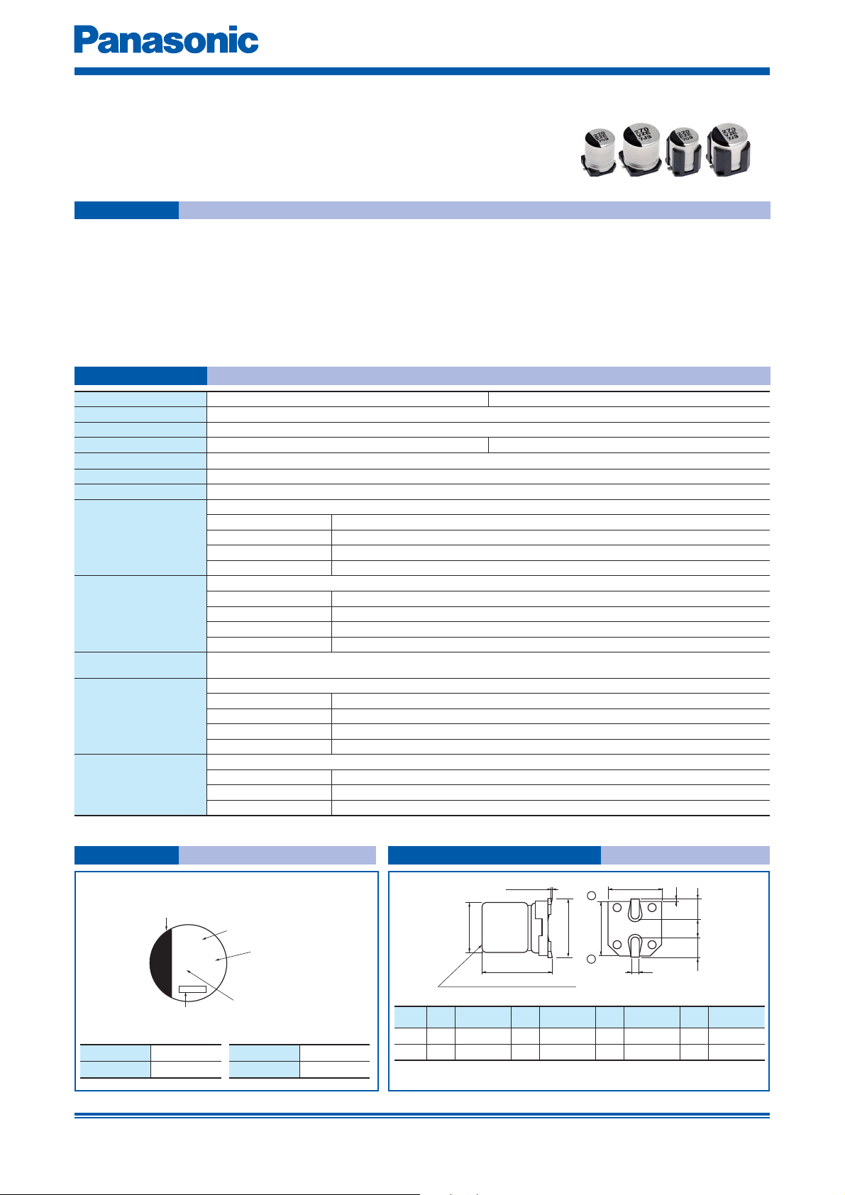
Marking Dimensions (not to scale)
Example : 25 V.DC 220 µF Marking color : BLACK
Negative polarity marking (–)
220
Capacitance (µF)
Series identification
0D±0.5
ZEE
Pressure relief (010 and larger)
Lot number
Rated voltage mark
E 25 V.DC
V 35 V.DC
Design and specifications are each subject to change without notice. Ask factory for the current technical specifications before purchase and/or use.
Should a safety concern arise regarding this product, please be sure to contact us immediately.
Rated voltage mark
H 50 V.DC
J 63 V.DC
Size
D L A, B H I W P K
code
F 8.0 10.2±0.3 8.3 10.0 max. 3.4 0.90±0.2 3.1 0.70±0.2
G 10.0 10.2±0.3 10.3 12.0 max. 3.5 0.90±0.2 4.6 0.70±0.2
The dimensions of the vibration-proof products, please refer to the page of
·
the mounting specifi cation.
0.3 max.
H
L
–
+
B±0.2
A±0.2
K
W
( ) Reference size
(I)
(P)
(I)
(Unit : mm)
Mar. 201700
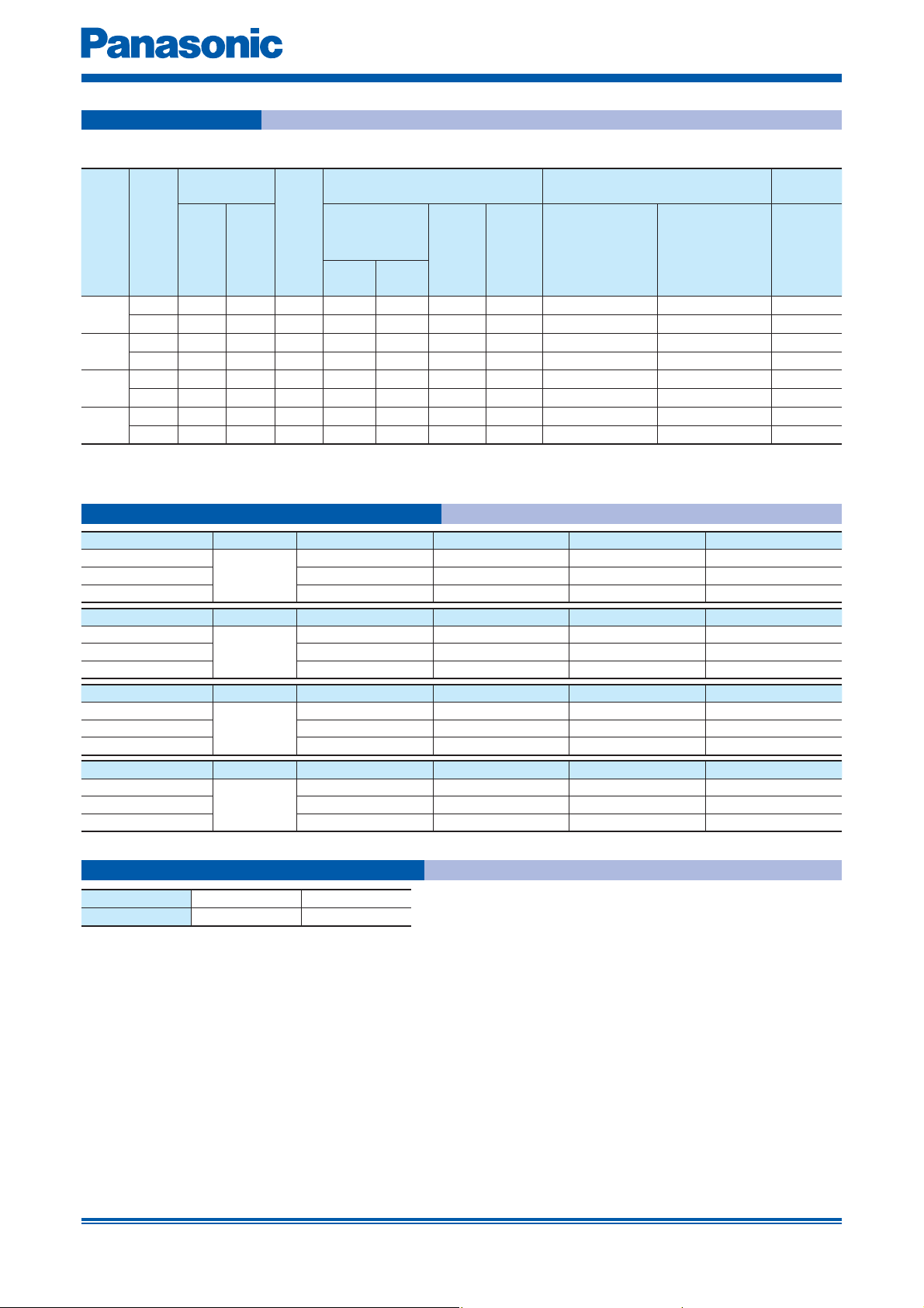
Conductive Polymer Hybrid Aluminum Electrolytic Capacitors
Standard products
Case size
Rated
voltage
(V.DC)
· Please refer to the page of “Refl ow profi le” and “The taping dimensions”.
Capaci-
tance
(±20 %)
(µF)
220 8 10.2 F 700 1600 27 0.14 EEHZE1E221P EEHZE1E221V 500
25
330 10 10.2 G 900 2000 20 0.14 EEHZE1E331P EEHZE1E331V 500
150 8 10.2 F 700 1600 27 0.12 EEHZE1V151P EEHZE1V151V 500
35
270 10 10.2 G 900 2000 20 0.12 EEHZE1V271P EEHZE1V271V 500
50
63
68 8 10.2 F 600 1250 30 0.10 EEHZE1H680P EEHZE1H680V 500
100 10 10.2 G 80 0 1600 28 0.10 EEHZE1H101P EEHZE1H101V 500
33 8 10.2 F 600 1100 40 0.08 EEHZE1J330P EEHZE1J330V 500
56 10 10.2 G 800 1400 30 0.08 EEHZE1J560P EEHZE1J560V 500
(mm)
DL
f
Size
code
Ripple current
(100 kHz)
(mA r.m.s.)
Endurance 1
(+145 °C)
Specifi cation Part number
ESR
Endurance 2
(+135 °C)
(10 0 kHz)
(+2 0 ° C)
(mΩ)
(120 Hz)
(+2 0 ° C)
tan
Endurance 1 : 145 °C 2000 h
Endurance 2 : 135 °C 4000 h
Min.
packaging q'ty
d
Standard
Product
Vibration-proof
product
Tap ing
(pcs)
Frequency correction factor for ripple current
Rated capacitance Frequency 100 Hz < f < 200 Hz 200 Hz < f < 300 Hz 300 Hz < f < 500 Hz 500 Hz < f < 1 kHz
C < 47
µF
47
µF < C < 150 µF 0.15 0.20 0.25 0.30
150
µF < C 0.15 0.25 0.25 0.30
Rated capacitance Frequency 1 kHz < f < 2 kHz 2 kHz < f < 3 kHz 3 kHz < f < 5 kHz 5 kHz < f < 10 kHz
C < 47
µF
47
µF < C < 150 µF 0.40 0.45 0.55 0.60
150
µF < C 0.45 0.50 0.60 0.65
Rated capacitance Frequency 10 kHz < f < 15 kHz 15 kHz < f < 20 kHz 20 kHz < f < 30 kHz 30 kHz < f < 40 kHz
C < 47
µF
47
µF < C < 150 µF 0.70 0.75 0.80 0.80
150
µF < C 0.75 0.80 0.85 0.85
Rated capacitance Frequency 40 kHz < f < 50 kHz 50 kHz < f < 100 kHz
C < 47 µF
47
µF < C < 150 µF 0.85 0.90 1.00 1.00
150
µF < C 0.85 0.90 1.00 1.00
Correction
factor
Correction
factor
Correction
factor
Correction
factor
0.10 0.10 0.15 0.20
0.30 0.40 0.45 0.50
0.60 0.65 0.70 0.75
100 kHz < f < 500 kHz
0.80 0.85 1.00 1.05
500 kHz
< f
After endurance ESR (100 kHz, –40 °C)
Size
ESR (Ω) 0.4 0.3
8×10.2
f
10×10.2
f
Design and specifications are each subject to change without notice. Ask factory for the current technical specifications before purchase and/or use.
Should a safety concern arise regarding this product, please be sure to contact us immediately.
Mar. 201700
 Loading...