

Page 1

Magi’c Box
User manual
Electromechanical Control Business Division
Industrial Solutions Company
Panasonic Corporation
Product description
Magi’c Box
Part Number
-
Panasonic’s part number
-
Country of origin
Japan
Application
Consumer wireless control system
Model number
ZERS1901
Page 2
1. System Overview
This product is a two-button switch unit used in consumer wireless control system.
When the switch button is pressed by the operation of a lever etc. into which this
product is embedded, electric power is generated by its mechanical operation. The
generated electric power is used to transmit information such as which of the two
buttons is pressed using 2.4GHz to a wireless receiver of a wireless control system
installed at a remote location. The wireless receiver that has received the signal reads
the switch unit ID and the state of each button from the signal, and outputs the read
signal to the external devices as a control signal.
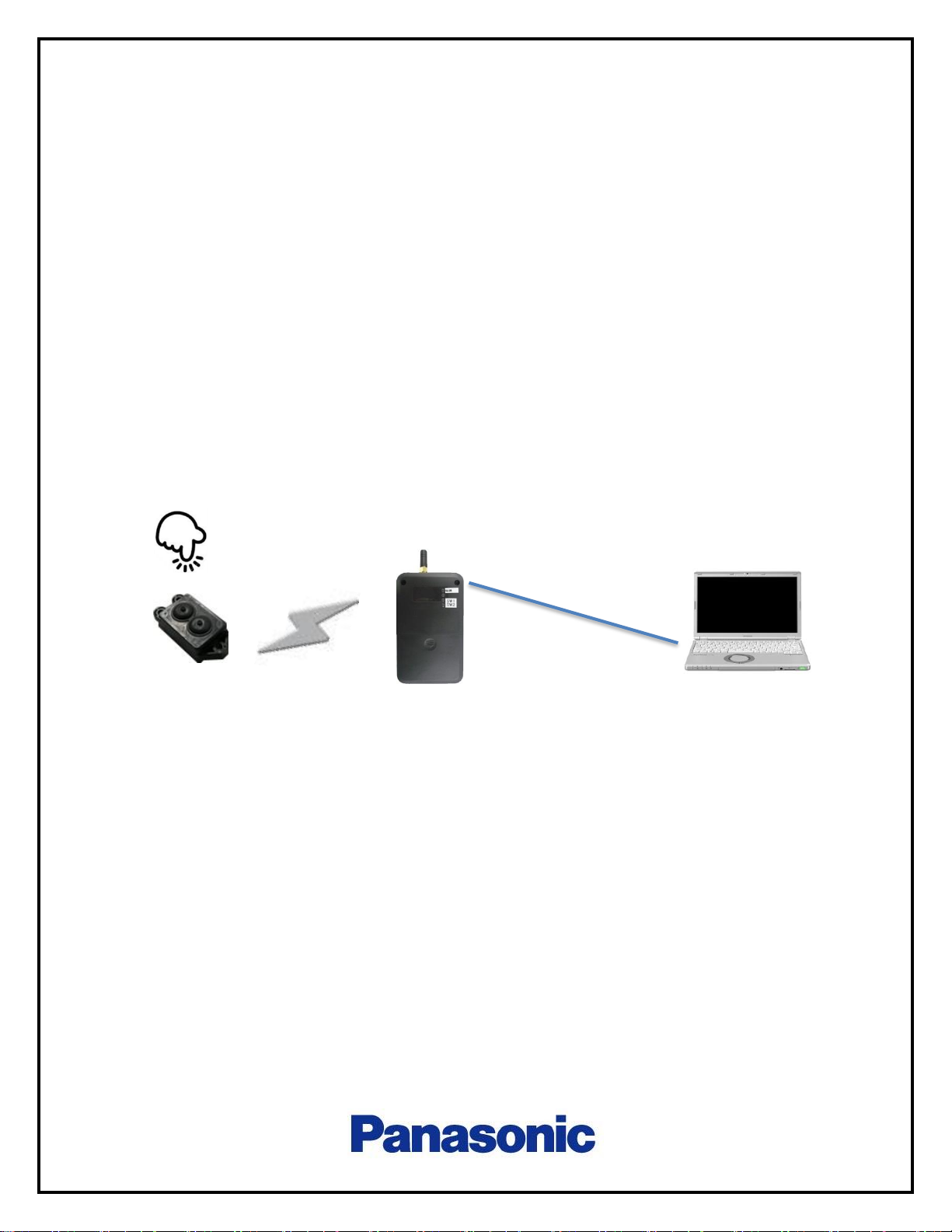
The following diagram shows the wireless control system example for the
demonstration purpose. It consists of one Magi’c box (transmitter switch) and one
receiver and a windows 64bit PC.
Fig.1 System Overview of wireless control system
Receiver
Windows 64bit PC
Magi’c box
(Transmitter switch)
USB Cable
2.4Ghz
Page 3

1.1. Precautions
This device complies with part 15 of the FCC Rules. Operation is subject to the following
two conditions:
(1) This device may not cause harmful interference, and (2) this device must accept any
interference received, including interference that may cause undesired operation.
FCC CAUTION
Changes or modifications not expressly approved by the party responsible for compliance
could void the user’s authority to operate the equipment.
Note: This equipment has been tested and found to comply with the limits for a Class B
digital device, pursuant to part 15 of the FCC Rules. These limits are designed to provide
reasonable protection against harmful interference in a residential installation. This
equipment generates, uses and can radiate radio frequency energy and, if not installed
and used in accordance with the instructions, may cause harmful interference to radio
communications. However, there is no guarantee that interference will not occur in a
particular installation. If this equipment does cause harmful interference to radio or
television reception, which can be determined by turning the equipment off and on,
the user is encouraged to try to correct the interference by one or more of the following
measures:
- Reorient or relocate the receiving antenna.
- Increase the separation between the equipment and receiver.
- Connect the equipment into an outlet on a circuit different from that to which the
receiver is connected.
- Consult the dealer or an experienced radio/TV technician for help.
This transmitter must not be co-located or operated in conjunction with any other antenna
or transmitter.
This equipment complies with FCC radiation exposure limits set forth for an uncontrolled
environment and meets the FCC radio frequency (RF) Exposure Guidelines as this
equipment has very low levels of RF energy.
Page 4
2. Magi’c Box Overview
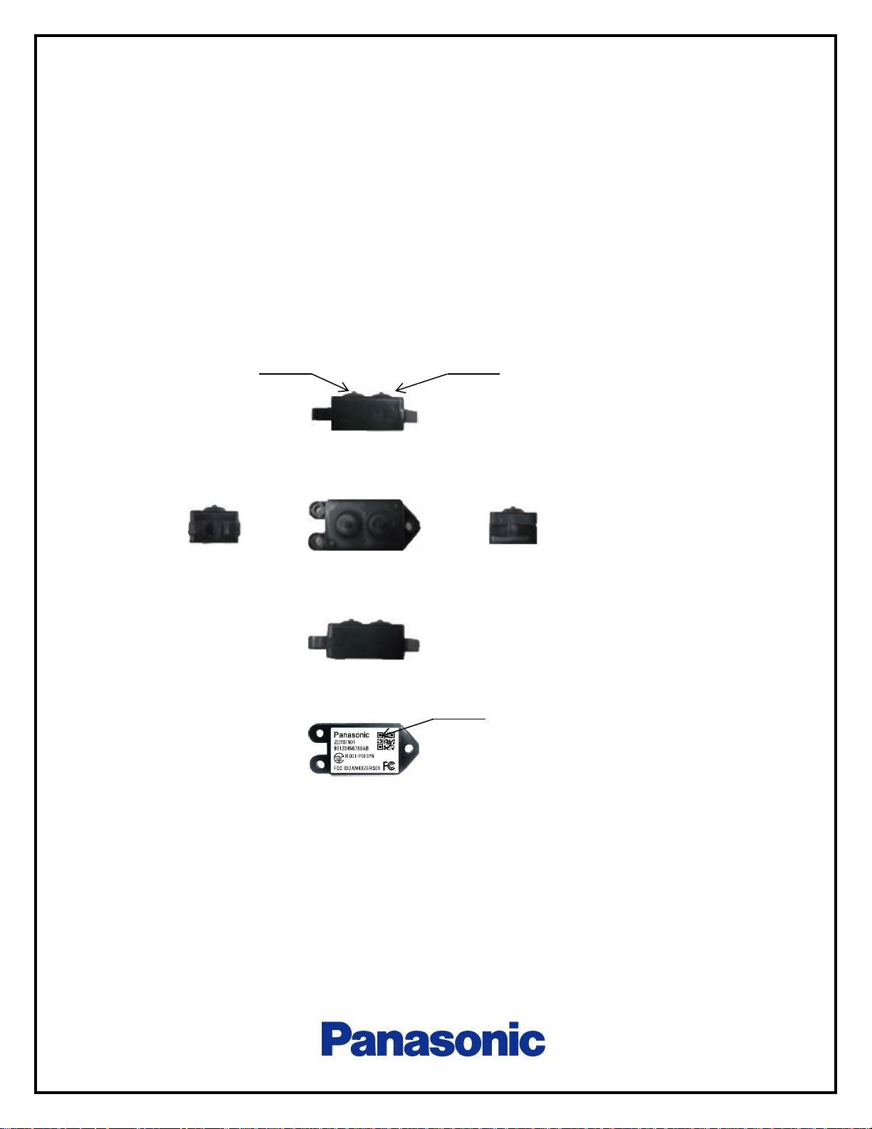
The following pictures shows the Magi’c box appearance.
It has two button, A and B. It transmit data when these buttons are pushed.
Fig.2 Pictures of Magi’c box
Top
Side
Side
Bottom
Front
Back
A Button
B Button
Label
Page 5

3. Test Receiver
The following pictures shows the test receiver for theMagi’c box switch.
Fig.2 Pictures of Test Receiver
3.1. LED
Test receiver has three LED and those display is defined as follows.
LED name
Lights up
Blink
Power
Power active
3 times blink : cypher key exchanged done
SW 1
-
Received signal (SW1 ON)
SW2 - Received signal (SW2 ON)
Antenna
LED Indicator
Power switch
USB Connector
Page 6

4. Setup of test receiver
4.1. Installing USB driver to PC
Prior to connect the test receiver to PC, please install the USB driver which is
provided by FTDI, D2XX Direct driver (CDM v2.12.28 WHQL Certified.zip) to you PC.
The driver should be for Windows OS 64bit version.
4.2. Installing application software to PC
Please install application software, Setup_Test_Receiver_1.0.xlsm on your PC. It
is a Microsoft Excel Macro. It can be installed to any directory. The dll file,
cypher_gen64.exe should be installed to c:\test_receiver
Fig.4 Image of Setup_Test_Receiver_1.0.xlsm
Page 7

4.3. Setting of Test receiver
(1) Power slide switch should be set to USB side
(2) Connect test receiver to PC by USB cable
(3) Check if the power indicator lights up or not.
(4) Start a terminal software, like “tera term” on PC
(5) Set the the terminal software to be as follows
Serial port communication
Baud rate : 115200
Data: 8bit
Parity: none
Stop bit : 1 bit
Flow control : none
Terminal return code setting : CR+LF (both TX and RX)
Local echo : ON
Page 8

4.4. Connecting serial port of test receiver with PC
Push the button as follows to connect serial port of test receiver with PC.
Fig.5 Connecting serial port test receiver with PC
4.5 Paring Magi’c box to test receiver
(1) Enter the address of Magi’c box that you want to pair to yellow box.
The length of address should be 12 characters 0-9, a-f
(2) Push the “generate initial key” button
(3) Push the “Write” button
(4) Push the “Read” button to check if writing has been done correctly.
(5) Push the “Key exchange” button
(6) Push the Magi’c box button several times.
Push the button until the
display gets “Port Close”
Page 9

Fig.6 Paring Magi’c box to test receiver
(1)
(2)
(3)
(4)
(5)
Page 10

5 Logout message
The example of Logout messages are shown as below.
If the pairing has not been completed, the payload cannot be decrypted as the third
line message.
Fig.7 Logout message example when pairing is not complete
Fig.8 Logout message example when pairing is complete
Time stamp
Magi’c box address
RSSI
SW A or B
10: Decrypted success
Decrypted payload
Sequence num
Rx OK
Payload( not decrypted)
Time stamp
RSSI
Log out
Log out
Page 11

6 Contacts
(1) USA
Panasonic Industrial Devices Sales Company of America
Address:205 Ravendale Drive, Mountain View, CA 94043
+1-201-341-6081
(2) Japan
Electromechanical Control Business Division
Industrial Solution Company
Panasonic Corporation
Address:1006 Oaza Kadoma Kadoma City, Osaka 571-8506
+81-50-3487-8129
 Loading...