

Page 1

Operating
Instructions
ZEQUO 6400
Model Number: PN36240E
Thank you for purchasing our product.
This manual provides important information about safe and proper
operations of this Switching Hub.
Please read "Important Safety Instructions" on pages 6 to 8 before use.
Under all circumstances, customer disassembling of this Switching Hub voids
the warranty.
Page 2

2
The target model for this Operating Instruction is as follows.
Model name Model number Firmware version
ZEQUO 6400
PN36240E-ID
1.0.1.34
PN36240E-TH
PN36240E-MY
PN36240E-SG
Page 3

4
Table of Contents
1. Product Outline ..................................................................................................... 11
2. Installation ............................................................................................................. 18
3. Connection ............................................................................................................ 19
4. Using Command Line Interface ............................................................................ 23
5. Basic Management Commands ............................................................................ 30
6. 802.1X Commands ................................................................................................ 54
7. Access Control List (ACL) Commands ................................................................... 88
8. Access Control List (ACL) Egress Command List ................................................. 117
9. ARP Commands ................................................................................................... 143
10. Asymmetric VLAN Commands ............................................................................ 150
11. Auto Configuration Commands ......................................................................... 153
12. Basic IP Commands ............................................................................................. 156
13. Bootup Function Commands .............................................................................. 171
14. BPDU Attack Protection Commands .................................................................. 174
15. Cable Diagnostics Commands ............................................................................. 180
16. Command List History Commands ...................................................................... 183
17. Command Logging Command List ..................................................................... 187
18. Network Access Authentication Command List ................................................. 191
19. Didital Diagnostic Monitoring (DDM) Commands ............................................. 200
20. Debug Software Command List .......................................................................... 218
21. DHCP Local Relay Commands ............................................................................. 263
22. DHCP Relay Commands ...................................................................................... 268
23. DHCP Server Commands ..................................................................................... 287
24. DHCP Snooping Commands ............................................................................... 310
25. DHCPv6 Relay Command List .............................................................................. 315
26. DHCPv6 Server Commands ................................................................................. 321
27. Distance Vector Multicast Routing Protocol (DVMRP) Commands ................... 337
28. Domain Name System (DNS) Relay Commands ................................................. 345
29. DNS Resolver Commands .................................................................................... 351
30. FDB Commands ................................................................................................... 359
31. File System Management Commands ................................................................ 370
32. Filter Commands ................................................................................................. 382
33. Gratuitous ARP Commands ................................................................................ 389
34. Internet Group Management Protocol (IGMP) Commands .............................. 396
35. IGMP Proxy Commands ...................................................................................... 405
36. IGMP Snooping Commands ................................................................................ 411
37. IP Multicasting Commands ................................................................................. 433
38. IP Routing Commands ........................................................................................ 436
39. IP Source Address Verify Commands .................................................................. 446
40. IPv6 NDP Commands .......................................................................................... 460
41. Jumbo Frame Commands ................................................................................... 469
42. LACP Configuration Commands ......................................................................... 473
43. Layer 2 Protocol Tunneling (L2PT) Command List ............................................. 476
44. Limited Multicast IP Address Commands ........................................................... 481
45. Link Aggregation Commands ............................................................................. 491
Page 4

5
46. LLDP Commands ................................................................................................. 497
47. Loopback Interface Commands .......................................................................... 525
48. MAC Notification Commands ............................................................................. 529
49. MAC-based Access Control Commands .............................................................. 534
50. MD5 Commands ................................................................................................. 556
51. Mirror Commands ............................................................................................... 560
52. MLD Proxy Commands ........................................................................................ 567
53. MLD Snooping Commands ................................................................................. 573
54. Login Banner and Prompt Commands ............................................................... 594
55. Multicast Listener Discovery (MLD) Commands ................................................. 595
56. Network Load Balancing (NLB) Commands ....................................................... 601
57. Network Management Commands .................................................................... 605
58. Network Monitoring Commands ........................................................................ 624
59. Open Shortest Path First (OSPF) Command List ................................................. 646
60. OSPFv3 Commands ............................................................................................. 672
61. Packet Storm Commands .................................................................................... 696
62. Protocol Independent Multicast (PIM) Commands ............................................ 702
63. PIM for IPv6 Command List ................................................................................ 724
64. Policy Route Commands ..................................................................................... 747
65. Port Security Commands ..................................................................................... 751
66. Power Saving Commands ................................................................................... 761
67. Precision Time Protocol (PTP) Commands .......................................................... 764
68. Protocol VLAN Commands ................................................................................. 785
69. QoS Commands ................................................................................................... 792
70. Ring Redundant Protocol (RRP) Commands ...................................................... 814
71. Routing Information Protocol (RIP) Command List ........................................... 824
72. RSPAN Commands .............................................................................................. 830
73. SNMPv1/v2/v3 Commands ................................................................................. 838
74. Spanning Tree Protocol (STP) commands .......................................................... 859
75. SSH Commands ................................................................................................... 876
76. Stacking Commands ............................................................................................ 886
77. Static MAC-based VLAN Commands .................................................................. 895
78. Subnet VLAN Commands .................................................................................... 899
79. Switch Port Commands ....................................................................................... 906
80. System Severity Commands ................................................................................ 912
81. Tech Support Commands .................................................................................... 914
82. Time and SNTP Commands ................................................................................. 917
83. Traffic Segmentation Commands ....................................................................... 925
84. Utility Commands ................................................................................................ 927
85. Virtual Router Redundancy Protocol (VRRP) Command List ............................. 956
86. Voice VLAN Commands ...................................................................................... 967
87. VLAN Commands ................................................................................................ 978
88. VLAN Trunking Commands ................................................................................. 996
89. Web-based Access Control (WAC) Commands ................................................. 1001
90. Weighted Random Early Detection (WRED) Commands ................................. 1018
91. System Log Lists ................................................................................................ 1026
92. Appendix A. Specifications ............................................................................... 1052
93. Appendix B. Procedures for Configuration Using ZEQUO assist Plus .............. 1056
94. Troubleshooting ................................................................................................ 1057
95. Warranty and After-sales Service ...................................................................... 1058
Page 5

Important Safety Instructions
6
This chapter contains important safety instructions for preventing bodily
injury and/or property damage. You are required to follow them.
■Severity of bodily injury and/or property damage, which could result
from
incorrect use of the Switching Hub, are explained below.
This symbol indicates a potential hazard that
could result in serious injury or death.
This symbol indicates safety instructions.
Deviation from these instructions could lead to
bodily injury and/or property damage.
■The following symbols are used to classify and describe the type of
instructions to be observed.
This symbol is used to alert users
to what they must not do.
This symbol is used to alert users
to what they must do.
●Do not use power supply other than AC 100 - 240 V.
Deviation could lead to fire, electric shock, and/or equipment fa
ilure.
●Do not handle the power cord with wet hand.
Deviation could lead to electric shock, and/or equipment failure.
●Do not handle this Switching Hub and connection cables during a
thu
nderstorm.
Deviation could lead t
o electric shock.
●Do not disassemble and/or modify this Switching Hub.
Deviation could lead to fire, electric shock, and/or equipment fa
ilure.
●Do not damage the power cord. Do not bend too tightly, stretch,
twist, bundle with other cord, pinch, put under a heavy object,
and/or heat it.
A damaged power cord could lead to fire, short, and/or electric
sho
ck.
●Do not put foreign objects (such as metal or combustibles) into the
opening (such as twisted pair port, console port, SFP extension slot,
S
FP+ extension slot, or SD card slot), and/or do not drop them into
the
inside of the Switching Hub.
Deviation could lead to fire, electric
shock, and/or equipment
failure.
Page 6

●Do not connect equipments other than 10BASE-T/100BASE-TX/
1000BASE-T to twisted pair port.
Deviation could lead to fire, electric
shock, and/or equipment
failure.
●Do not place this Switching Hub in harsh environment such as near
water, high humid, and/or high dust.
Deviation could lead to fire, electric
shock, and/or equipment
failure.
●Do not place this Switching Hub under direct sun light and/or high
temperature.
Deviation could lead to high inter
nal temperature and fire.
●Do not install this Switching Hub at the location with continuous
v
ibration or strong shock, or at an unstable location.
Deviation could lead to injury and/or equipment failure.
●Do not install any module other than our optional SFP modules
(PN
54021K/PN54023K) to SFP/SFP+ exstension slot.
Deviation could lead to fire, electric shock, and/or equipment failure.
●Do not install any module other than our optional SFP+ modules
(PN
59021/PN59023) to SFP/SFP+ exstension slot.
Deviation could lead to fire, electric shock, and/or equipment failure.
●Do not install any module other than our optional SFP+ direct
attach
cable to stacking port.
Deviation could lead to fire, electric shock, and/or equipment failure.
●Do not put this Switching Hub into fire.
Deviation could lead to explosion and/or fire.
●Do not use the supplied power cord for anything other than this
pr
oduct.
Deviation could lead to fire, electric shock, and/or equipment failure.
7
Page 7
●Use the bundled power cord (AC 100 - 240 V specifications).
Deviation could lead to electric shock, malfunction, and/or equipment
failure.
●Unplug the power cord in case of equipment failure.
Deviation, such as keeping connected for a long time, could lead
to
fire.
●Connect this Switching Hub to ground.
Deviation could lead to electric shock, malfunction, and/or equipment
failure.
●Connect the power cord firmly to the power port.
Deviation could lead t
o electric shock, and/or malfunction.
●Unplug the power plug if the STATUS LED blinks in orange (system
fault).
Deviation, such as keeping connected for a long time, could lead to
fire.
●Handle the Switching Hub carefully so that fingers or hands may
not
be damaged by twisted pair ports, SFP/SFP+ extension slots,
console port, SD card slot, or power cord hook block.
8
Page 8

Basic Instructions for the Use of This Product
●For internal inspection and/or repair, please contact the shop.
●Use commercial power supply from
a wall socket, which is close and easily
accessible to this Switching Hub.
●Unplug the power cord when installing, moving, or cleaning this Switching
Hub.
●Use this Switching Hub within the specifications. Deviation cou
ld lead to
malfunctions.
●Do not touch the metal terminal of the RJ45 connector, the modular plug
of
connected twisted pair cable and serial port, or the metal terminal of the
SFP/SFP+ extension slot. Do not place charged objects in the proximity of
the
m. Static electricity could le
ad to equipment failure.
●Do not put the modular plug of the connected twisted pair cable on objects
that
can carry static charge, such as a carpet. Do not place it in the proxim-
ity. Static electricity could lead to equipmen
t failure.
●Before connecting a console cable to the console port, discharge
static elec-
tricity, for example by touching metal appliance (do not dischar
ge by
touching this Switching Hub).
●Do not put a strong shock, including dropping, to this Switching Hub.
Deviation could lead to equipment failure.
●Do not store and/or use this Switching Hub in the environment with the
characteristics listed below.
(Store and/or use this Switching Hub in the environment in accordance with the
specifica
tion.)
- High humidity. Possible spilled liquid (water).
- Dusty. Possible static charge (such as carpet).
- Under direct sunlight.
- Possible condensation. High/low temperature exceeding the
environment specifications.
- Strong vibration and/or strong shock.
●Please use this Switching Hub in place where ambient temperatur
e is from
0 to 40 degrees C. Failure to meet the above conditions may result in fire,
electric shock, breakdown, and/or malfunction. Please take notice because
such cases are out of guarantee. Additionally, do not cover the bent hole of
this Switching Hub. Deviation could lead to high internal temperature,
equipment failure and/or malfunction.
●When stacking Switching Hubs, leave a minimum of 20 mm space be
tween
them.
●When connecting the stacks, be sure to use firmware versions th
at are
indentical for all of the devices. Please note that operations are not guaran-
teed if the firmware versions are different.
●Please note that operation will
not be guaranteed if any SD card other than
the separately sold Panasonic SD card is installed into the SD card slot.
Format the card with this Switching Hub.
9
Page 9

10
1. Panasonic will not be liable for any damage resulting from the operation not
in accordance with this operation manual or loss of communications, which
may or may not be caused by failure and/or malfunction of this
product.
2. The contents described in this document may be changed without prior
notice.
The latest version is available on our web site.
3. For any questions, please contact the shop where you purchased the product.
* Brands and product names in this document are trademarks or registered
trademarks of their respective holders.
Page 10

1. Product Outline
11
1. Product Outline
ZEQUO 6400 is a Layer-3 All Gigabit Ethernet Switching Hub with man-
agement functions, equipped with 24 10/100/1000BASE-T ports, four
1000BASE-X SFP extension slots, and four 1000BASE-X/10GBASE-X
extension slots.
1.1. Features
Ports 1 to 24 (copper ports) are 10BASE-T/100BASE-TX/1000BASE-T ports correspond-
ing to auto negotiation.
Ports 21 to 24 are SFP extension ports. You can select either of 1000BASE-T supported
copper port or SFP port for use.
Ports 25 to 28 are SFP/SFP+ extension ports. Capable of 10 Gbps communications
with SFP+ module.
Ports 27 to 28 can also be used as stack ports.
Up to four units of ZEQUO 6400 or ZEQUO6500 can be connected in a stack with
SFP+ modules and optical fiber cables, or SFP+ direct attach cables.
A SD card can be used to change and save configuration and firmware.
All copper ports support the straight/cross cable via auto sensing function.
You can simply connect devices with straight cables, whether the target is a terminal or
a network device.
The Power Saving Mode detects the connection status automatically and saves power
consumption to minimum.
The auto negotiation function is supported, allowing to easily support a heteroge-
neous environment of 10BASE-T, 100BASE-TX, and 1000BASE-T. The speed and com-
munication mode can be set at Fixed.
The Ping command can be used to verify communications.
The standard MIB (MIB II, Bridge MIB, RMON four groups, etc.) is supported, allowing
to manage the Switching Hub from the SNMP manager. (For details, refer to Appendix
A.)
The support application “ZEQUO assist Plus” supports GUI-based easy configura-
tion for installation.
RIP is supported, allowing to dynamically build a network.
OSPF is supported, allowing for efficient routing even in a large-size network.
PIM-SM/PIM-DM/PIM-SM-DM/PIM-SSM are supported, allowing for efficient multicast
routing.
Page 11

1. Product Outline
12
Policy-based routing is supported, allowing for routing according to the access condi-
tions.
The Access Control function is supported, allowing to filter by IP address, MAC
address, protocol number, and L4 port number.
VRRP is supported, allowing for layer-3 Switching Hub redundancy.
Spanning Tree Protocol is supported, allowing to build a redundant system.
IEEE802.1Q tagged VLAN is supported, allowing to register up to 4094 VLANs.
The IEEE802.1p QoS function is supported.
The IEEE802.3ad Link Aggregation function is supported, allowing to configure up to 8
ports and 48 groups.
The IEEE802.1X authentication function is supported, allowing to block network access
from unregistered users.
The IGMP Snooping function is supported, allowing to prevent multicast packets
from monopolizing bandwidth.
The Ring Redundant Protocol (RRP) is supported, allowing to make a redundant
network via ring topology.
Page 12

1. Product Outline
13
1.2. Accessories
Please be sure to confirm the contents. Please contact your distributor if any of the con-
tents are insufficient.
ZEQUO 6400 main unit...................................................................1
Installation Guide............................................................................1
CD-ROM (including this Operating Instructions)............................1
Mounting brackets (for 19-inch rack mount).................................2
Screws (for 19-inch rack mount).....................................................4
Screws (for fixing the main unit and the mounting bracket).........8
SFP+ direct attach cable (1m)..........................................................1
Rubber foot.....................................................................................4
Dummy SD card...............................................................................1
Power cord (*).................................................................................1
(*) The attached power cord is dedicated for AC 100 - 240 V use.
1.3. Optional Accessories
PN54021K 1000BASE-SX SFP Module
PN54023K 1000BASE-LX SFP Module
PN59021 10GBASE-SR SFP+ Module
PN59023 10GBASE-LR SFP+ Module
Page 13

1. Product Outline
14
1.4. Part Names and Functions
ヴヵモヤレチリュチロユュ
Fig. 1-1 Back, Front, LEDs
● Power port
Connect the supplied power cord into the port and connect the other end into an elec-
tric outlet.
● Power cord hook block
Hooking the supplied power cord on the block makes the cord less likely to be
unplugged from the power port.
●Ground terminal
Connect the earth terminal screw and grounding surface using the earth wire.
●SD card slot
Insert a SD card to change configuration information and change and save firmware.
● 10BASE-T/100BASE-TX/1000BASE-T port (Ports 1 to 24)
Connect a 10BASE-T/100BASE-TX/1000BASE-T terminal hub repeater Switching Hub.
The length of the copper cabling (CAT5e or higher) connecting this Switching Hub and a
device
must be 100 m or shorter.
Page 14

1. Product Outline
15
● SFP extension port (Ports 21 to 24)
Install an SFP module. (These ports are exclusive usage with twisted pair ports.)
When SFP extension slot is linked, the port is automatically switched to fiber port mode.
SFP port supports only the full-duplex mode.
● SFP+ extension port (Ports 25 to 28)
Install an SFP or SFP+ module.
When the stacking function is enabled, port 27 and 28 become the stack-specific ports.
● Stacking port (Ports 27 to 28)
Up to four units can be stacked by connecting the SFP+ module and optical fiber
cables, or SFP+ direct attach cables when the stacking function is enabled.
●Console port
Used to connect a VT100 compatible terminal to configure and manage this Switching
Hub.
Transmission mode : RS-232C Emulation mode : VT100
Transmission speed : 9,600 bps Data length : 8 bits
Stop bit : 1 bit Parity control : None
Flow control : None Communication connector : RJ45
Use an RJ45-Dsub 9 pin console cable for connection.
Page 15

1. Product Outline
16
1.5. LED Behavior
1.5.1. LED Behavior at Starting-up
When you turn on this Switching Hub, all LEDs are lit momentarily. POWER LED lights
green and STATUS LED lights orange, and then the hardware self diagnosis is executed.
Upon finishing the diagnosis, both POWER and STATUS LEDs light green.
1.5.2. LED Behavior while Operating
This Switching Hub has a set of LEDs for each port. These LEDs indicate the operation sta-
tus of each port.
●System LED
LED Behavior Description
POWER LED Green Light Power is ON
Off Power is OFF
STATUS LED Green Light The system is operating nor-
mally.
Orange Light The system is staring up.
Orange Blink Malfunction
(Contact the shop)
SD CARD LED Green Light SD card is inserted
Green Blink Accessing to SD card
Orange Light SD card error
Off Not inserted
STACK ID LED "H" and STACK ID are displayed
alterna
tely.
Master device
"h" and STACK ID are displayed
alterna
tely.
Backup-master device
STACK ID only Slave device
● 10/100/1000BASE-T port LED (Ports 1 to 24)
LED Behavior Description
LINK/ACT. Green Light 1000Mbps link established in full-duplex.
Green Blink Transmitting/receiving packets in 1000Mbps
full-duplex.
Orange Light 10/100Mbps link established.
Orange Blink Transmitting/receiving packets at 10/
10
0Mbps.
Off No device connected.
Page 16
1. Product Outline
17
●SFP extension slot LED (Ports 21 to 24)
LED Behavior Description
LINK/ACT. Green Light 1000Mbps link established in full-duplex.
Green Blink Transmitting/receiving packets in 1000Mbps
full-duplex.
Off No device connected.
●SFP+ extension slot LED (Ports 25 to 28)
LED Behavior Description
LINK/ACT. Green Light 10Gbps link established in full-duplex.
Green Blink Transmitting packets in 10Gbps full-duplex.
Orange Light 1000Mbps link established.
Orange Blink Transmitting/receiving packets at 1000Mbps.
Off No device connected.
Page 17

2. Installation
18
2. Installation
2.1. Installing in a 19-inch Rack
Take out two mount brackets and eight screws (for securing the mount brackets to the
Switching Hub) from accessories, and secure a bracket to each of the right an
d left sides of
the Switching Hub via four screw holes.
Then, by using four supplied screws (for 19-inch rack mount) or
screws included with the
rack, firmly mount the Switching Hub in the rack.
Fig. 2-1 Installing in 19-inch Rack
The main unit can be placed 20 mm back on the
rack by changing the bracket fixing
position.
Fig. 2-2 Installing in 19-inch Rack (20 mm backword mounting)
Page 18

3. Connection
19
3. Connection
3.1. Connecting a Copper Cable Port
● Connection Cable
Use a CAT5e or higher compliant straight cable (copper cabling) with 8P8C RJ45 modular
plugs.
● Network Configuration
Fig. 3-1 Connection Configuration Example
The length of the cable connecting this Switching Hub and a device must be 100 m or
s
horter. When a terminal or a LAN device with auto negotiation function is connected to a
port, the port is automatically configured to the most appropriate performance mode.
When a terminal or a device without auto negotiation function is connected to a port, this
Sw
itching Hub automatically determines and sets
the communication speed; however, the
full-duplex/half-duplex configuration is set at half-duplex because the full-duplex/half-
duplex capability cannot be determined. When connecting a terminal or a device without
auto negotiation function, set the connection mode of the port to Fixed.
Note: If connection mode is set to a fixed value, Auto MDI/MDI-X function does not
work. Therefore, you need to use a cross cable for connections between
Switching Hubs.
Page 19
3. Connection
20
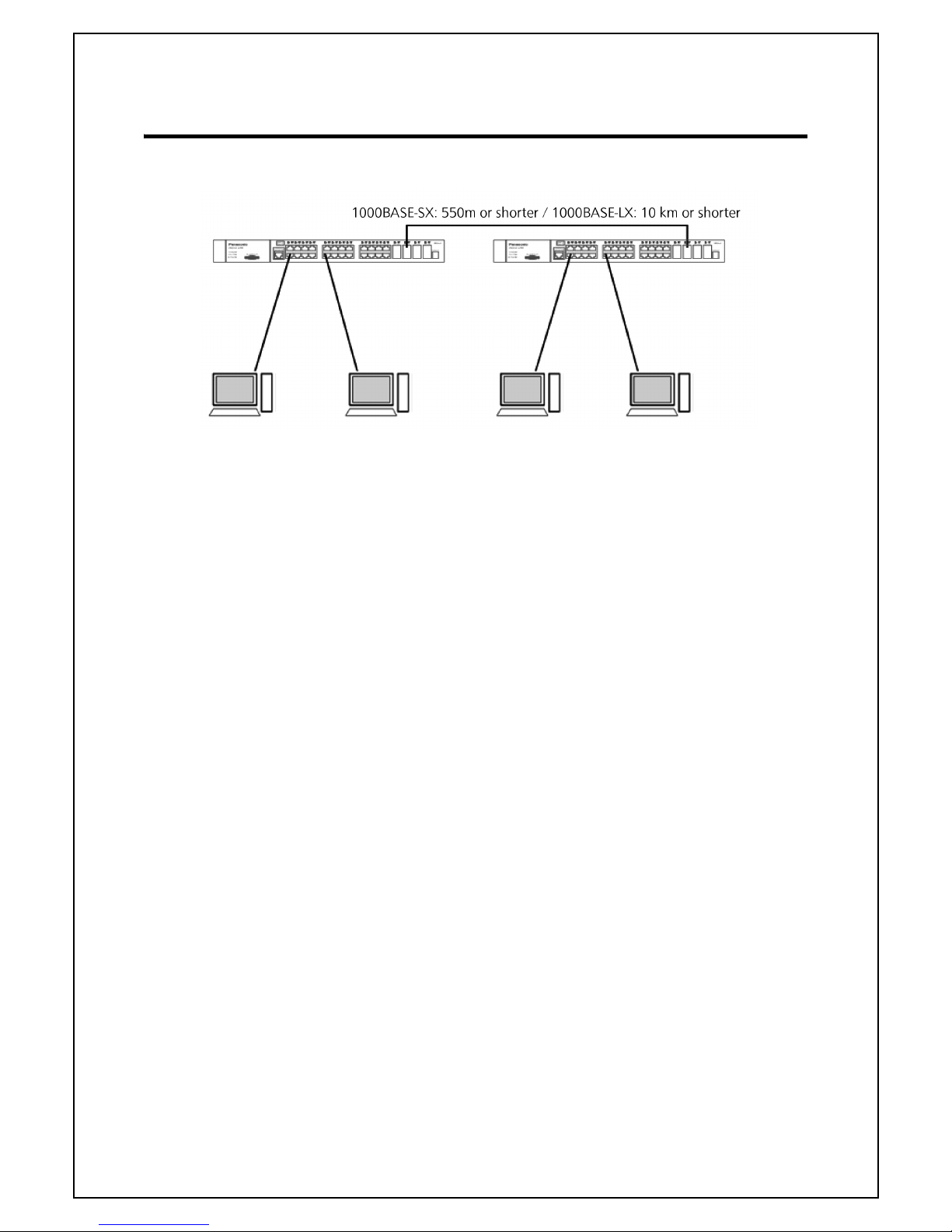
3.2. Connecting with an SFP Extension Slot
Fig. 3-2 Optical Fiber Cable Connection Example
Plugging an SFP module (optional) into an SFP extension slot enables an optical fiber con-
nection. By factory default, the copper
cable port is enabled, but the SFP extension port is
automatically enabled when a link is established.
Connect this Switching Hub's TX port to the RX port of
the connected device and this
Switching Hub's RX port to the TX port of the connected device.
The following SFP modules are optionally available:
- 1000BASE-SX SFP module (Part number: PN54021K)
- 1000BASE-LX SFP module (Part number: PN54023K)
Page 20

3. Connection
21
3.3. Connecting with an SFP+ Extension Slot
Fig. 3-3 Optical Fiber Cable Connection Example
Plugging an SFP/SFP+ module (optional) into an SFP+ extension slot enables an optical
fib
er connection.
Connect this Switching Hub's TX port to the RX port of
the connected device and this
Switching Hub's RX port to the TX port of the connected device.
The following SFP+ modules are optionally available:
- 10GBASE-SR SFP+ module (Part number: PN59021)
- 10GBASE-LR SFP+ module (Part number: PN59023)
Page 21

3. Connection
22
3.4. Connecting to Power
Connect the supplied power cord to the power port of this Switching Hub, and connect
the power plug into an electric outlet. The
Switching Hub operates at AC 100 - 240 V (50/
60 Hz).
It does not have a power switch. When you connect the power plug, the Switching Hub
turns on and starts operating. To power off, unplug the power plug from the electric out-
let.
Page 22

4. Using Command Line Interface
23
4. Using Command Line Interface
The Command Line Interface (CLI) is an operation screen to configure and
manage this Switching Hub.
You can use the CLI by connecting a VT-100 compatible terminal to the
serial port of this Switching Hub or through a remote connection such as
telnet.
This chapter describes the following CLI procedures.
Overview of connecting to the serial port
How to configure the IP address of this Switching Hub
Overview of how to use commands
- "?" command, which displays the command help
- Operations when parameters are omitted
- Using command autocomplete function and input history
- Operations when making a typo
Syntax rules
Available input editing keys and page operation keys
4.1. Accessing the Switch via the Serial Port
The Switch's serial port's default settings are as follows:
9600 baud
no parity
8 data bits
1 stop bit
A computer running a terminal emulation program capable of emulating a VT-100 terminal
and a serial port configured as above is then connected to the Switch's serial port via an RJ-
45 to RS-232 DB-9 convertor cable.
With the serial port properly connected to a management computer, the following screen
should be visible.
Zxxx0 Gigabit Ethernet Switch
Command Line Interface
Firmware: Build 1.0.x.xx
UserName:
Page 23

4. Using Command Line Interface
24
There is no initial username or password. Just press the Enter key twice to display the CLI
input cursor
- Zxxx0:admin#. This is the command line where all commands are input.
4.2. Setting the Switch's IP Address
Each Switch must be assigned its own IP Address, which is used for communication with
an SNMP network manager or other TCP/IP application (for example BOOTP, TFTP). The
Switch's default IP address is 10.90.90.90. You can change the default Switch IP address to
meet the specification of your networking address scheme.
The Switch is also assigned a unique MAC address by the factory. This MAC address cannot
be changed, and can be found on the initial boot console screen
- shown below or the
command show switch
.
The Switch's MAC address can also be found in the Web management program on the
Device Information (Basic Settings) window on the Configuration menu.
The IP address for the Switch must be set before it can be managed with the Web-based
manager. The Switch IP address can be automatically set using BOOTP or DHCP protocols,
in which case the actual address assigned to the Switch must be known.
Starting at the command line prompt, enter the commands config ipif System ipaddress
xxx.xxx.xxx.xxx/yyy.yyy.yyy.yyy. Where the x's represent the IP address to be assigned to the
IP interface named System and the y's represent the corresponding subnet mask.
Alternatively, you can enter config ipif System ipaddress xxx.xxx.xxx.xxx/z. Where the x's
represent the IP address to be assigned to the IP interface named System and the z
represents the corresponding number of subnets in CIDR notation.
The IP interface named System on the Switch can be assigned an IP address and subnet
mask which can then be used to connect a management station to the Switch's Telnet or
Web-based management agent
Boot Procedure V1.0.x.xx
-------------------------------------------------------------------------------
Power On Self Test ........................................ 100 %
MAC Address : 00-01-02-03-04-00
H/W Version : A1
Please Wait, Loading V1.0.0.xx Runtime Image .............. 100 %
UART init ................................................. 100 %
Starting runtime image
Device Discovery .......................................... 100 %
Configuration init ........................................ 100 %
Zxxx0:admin# config ipif System ipaddress 10.24.22.100/255.0.0.0
Command: config ipif System ipaddress 10.24.22.100/8
Success.
Zxxx0:admin#
Page 24
4. Using Command Line Interface
25
In the above example, the Switch was assigned an IP address of 10.24.22.100 with a
subnet mask of 255.0.0.0. The system message Success indicates that the command was
executed successfully. The Switch can now be configured and managed via Telnet, SNMP
MIB browser and the CLI or via the Web-based management agent using the above IP
address to connect to the Switch.
There are a number of helpful features included in the CLI. Entering the ? command will
display a list of all of the top-level commands.
When entering a command without its required parameters, the CLI will prompt you with a
Next possible completions: message.
In this case, the command config account was entered with the parameter <username>.
The CLI will then prompt to enter the <username> with the message, Next possible
completions:. Every command in the CLI has this feature, and complex commands have
several layers of parameter prompting.
In addition, after typing any given command plus one space, users can see all of the next
possible sub-commands, in sequential order, by repeatedly pressing the Tab key.
To re-enter the previous command at the command prompt, press the up arrow cursor key.
The previous command will appear at the command prompt.
Zxxx0:admin#?
Command: ?
..
?
cable_diag ports
cd
change drive
clear
clear address_binding dhcp_snoop binding_entry ports
clear address_binding nd_snoop binding_entry ports
clear arptable
clear attack_log
clear counters
clear dhcp binding
clear dhcp conflict_ip
clear dhcpv6 binding
CTRL+C ESC q Quit SPACE n Next Page ENTER Next Entry a All
Zxxx0:admin#config account
Command: config account
Next possible completions:
<username>
Zxxx0:admin#
Zxxx0:admin# config account
Command: config account
Next possible completions:
<username>
Zxxx0:admin# config account
Page 25

4. Using Command Line Interface
26
In the above example, the command config account was entered without the required
parameter <username>, the CLI returned the Next possible completions: <username>
prompt. The up arrow cursor control key was pressed to re-enter the previous command
(config account) at the command prompt. Now the appropriate username can be entered
and the config account command re-executed.
All commands in the CLI function in this way. In addition, the syntax of the help prompts
are the same as presented in this manual - angle brackets < > indicate a numerical value or
character string, braces { } indicate optional parameters or a choice of parameters, and
brackets [ ] indicate required parameters.
If a command is entered that is unrecognized by the CLI, the top-level commands will be
displayed under the Available commands: prompt.
The top-level commands consist of commands such as show or config. Most of these
commands require one or more parameters to narrow the top-level command. This is
equivalent to show what? or config what? Where the what? is the next parameter.
For example, entering the show command with no additional parameters, the CLI will then
display all of the possible next parameters.
Zxxx0:admin#the
Available commands:
.. ? cable_diag cd
change clear config
copy create debug del
delete dir disable download
enable erase format login
logout md move no
ping ping6 rd reboot
reconfig rename reset save
show telnet traceroute traceroute6
upload
Zxxx0:admin#
Page 26

4. Using Command Line Interface
27
Zxxx0:admin#show
Command: show
Next possible completions:
802.1p 802.1x access_profile account
accounting acct_client address_binding
arpentry asymmetric_vlan
attack_log auth_client auth_diagnostics
auth_session_statistics auth_statistics authen
authen_enable authen_login authen_policy
authorization autoconfig bandwidth_control
boot_file bpdu_protection broadcast_ping_reply
command command_history
community_encryption config
current_config ddm device_status dhcp
dhcp_local_relay dhcp_relay dhcp_server dhcpv6
dhcpv6_relay dhcpv6_server dnsr
dot1v_protocol_group dscp
dvmrp ecmp egress_access_profile
egress_flow_meter environment error
fdb filter flow_meter
gratuitous_arp greeting_message gvrp hol_prevention
host_name igmp igmp_proxy igmp_snooping
ip ipfdb ipif
ipif_ipv6_link_local_auto ipmc ipmroute
iproute ipv6 ipv6route jumbo_frame
l2protocol_tunnel lacp_port
limited_multicast_addr link_aggregation lldp
lldp_med log log_save_timing
log_software_module loopback
mac_based_access_control mac_based_access_control_local
mac_based_vlan mac_notification max_mcast_group
mcast_filter_profile mirror
mld mld_proxy mld_snooping multicast
multicast_fdb name_server nlb ospf
ospfv3 packet
per_queue pim pim-ssm
policy_route port port_group port_security
port_security_entry port_vlan ports
power_saving private_vlan ptp pvid
radius rcp rip
rmon route route_map
router_ports rspan scheduling
scheduling_mechanism serial_port session
snmp sntp ssh stack_device
stack_information stacking_mode storage_media_info stp
sub_vlan subnet_vlan switch
syslog system_severity tech_support terminal
time time_range traffic
traffic_segmentation trap trusted_host
utilization vlan vlan_precedence vlan_translation
vlan_trunk voice_vlan vrrp wac
Zxxx0:admin#
Page 27

4. Using Command Line Interface
28
In the above example, all of the possible next parameters for the show command are
displayed. At the next command prompt, the up arrow was used to re-enter the show
command, followed by the account parameter. The CLI then displays the user accounts
configured on the Switch.
4.3. Command Syntax Symbols
The following symbols are used to describe how command entries are made and values
and arguments are specified in this manual. The online help contained in the CLI and
available through the console interface uses the same syntax.
All commands are case-sensitive. Be sure to disable Caps Lock or any other
unwanted function that changes text case.
Syntax Description
angle brackets < > Encloses a variable or value. Users must specify the variable or value. For
example, in the syntax
create ipif <ipif_name 12> {<network_address>} <vlan_name 32>
{secondary | state [enable | disable] | proxy_arp [enable | disable] {local
[enable | disable]}}
users must supply an IP interface name for <ipif_name 12> and a VLAN
name for <vlan_name 32> when entering the command. DO NOT TYPE THE
ANGLE BRACKETS.
square brackets [ ] Encloses a required value or list of required arguments. Only one value or
argument must be specified. For example, in the syntax
create account [admin | operator | power_user | user] <username 15>
{encrypt [plain_text | sha_1] <password>}
users must specify either the admin-, operator-, power_user-level or user-
level account when entering the command. DO NOT TYPE THE SQUARE
BRACKETS.
vertical bar | Separates mutually exclusive items in a list. For example, in the syntax
reset {[config |system]} {force_agree}
users may choose config or system in the command. DO NOT TYPE THE
VERTICAL BAR.
braces { } Encloses an optional value or a list of optional arguments. One or more
values or arguments can be specified. For example, in the syntax
config dhcp_relay {hops <int 1-16> | time <sec 0-65535>}(1)
users may choose config or system in the command. DO NOT TYPE THE
BRACES.
parentheses ( ) Indicates at least one or more of the values or arguments in the preceding
syntax enclosed by braces must be specified. For example, in the syntax
config dhcp_relay {hops <int 1-16> | time <sec 0-65535>}(1)
users have the option to specify hops or time or both of them. The "(1)"
following the set of braces indicates at least one argument or value within
the braces must be specified. DO NOT TYPE THE PARENTHESES.
ipif <ipif_name 12>
metric <value 1-31>
12 means the maximum length of the IP interface name.
1-31 means the legal range of the metric value.
ワヰヵユ
ワヰヵ
ユ
Page 28

4. Using Command Line Interface
29
4.4. Line Editing Keys
The screen display pauses when the show command output reaches the end of the page.
4.5. Multiple Page Display Control Keys
Keys Description
Delete Delete character under cursor and shift remainder of line to left.
Backspace Delete character to left of cursor and shift remainder of line to left.
Ctrl+R Toggle on and off. When toggled on, inserts text and shifts previous text to
right.
Up Arrow Repeats the previously entered command. Each time the up arrow is pressed,
the command previous to that displayed appears. This way it is possible to
review the command history for the current session. Use the down arrow to
progress sequentially forward through the command history list.
Down Arrow The down arrow will display the next command in the command history
entered in the current session. This displays each command sequentially as it
was entered. Use the up arrow to review previous commands.
Left Arrow Move cursor to left.
Right Arrow Move cursor to right
Tab Help user to select appropriate token.
Keys Description
Space Displays the next page.
Ctrl+C Stops the display of remaining pages when multiple pages are to be
displayed.
Esc Stops the display of remaining pages when multiple pages are to be
displayed.
n Displays the next page.
p Displays the previous page.
q Stops the display of remaining pages when multiple pages are to be
displayed.
r Refreshes the pages currently displayed.
a Displays the remaining pages without pausing between pages.
Enter Displays the next line or table entry.
Page 29

5. Basic Management Commands
30
5. Basic Management Commands
This chapter describes the basic management commands for this
Switching Hub.
Creating, editing, displaying, and deleting the accounts of users to manage this
Switching Hub
Up to eight user accounts can be created.
Encrypting the login password and configuration file
Displaying users who are currently logged in to the console
Displaying and managing the status of power, temperature, and fan on this
Switching Hub
Configuring the serial port (serial port) setting
Pausing the screen page feed, configuring the terminal width, and clearing the
screen
Using Telnet
Saving configuration and log files to NV-RAM
Resetting and rebooting
Logging in and logging out
create account [admin | operator | power_user | user] <username 15> {encrypt [plain_text |
sha_1] <password>}
enable password encryption
disable password encryption
config account <username> {encrypt [plain_text | sha_1] <password>}
show account
delete account <username>
show session
show switch
show environment
config temperature [trap | log] state [enable | disable]
config temperature threshold {high <temperature -500-500> | low <temperature -500-500>}(1)
show serial_port
config serial_port {baud_rate [9600 | 19200 | 38400 | 115200] | auto_logout [never |
2_minutes | 5_minutes | 10_minutes | 15_minutes]}(1)
enable clipaging
disable clipaging
enable telnet {<tcp_port_number 1-65535>}
disable telnet
save {[config <pathname> | log | all]}
reboot {force_agree}
reset {[config | system]} {force_agree}
login
logout
ワヰヵユ
ワヰヵ
ユ
Page 30

5. Basic Management Commands
31
5.1. create account
Description
This command creates user accounts. The username is between 1 and 15 characters,
the password is between 0 and 15 characters. The number of accounts (including
admin, operator, and user) is up to eight.
Format
create account [admin | operator | power_user | user] <username 15> {encrypt
[plain_text | sha_1] <password>}
Parameters
Restrictions
Only Administrator-level users can issue this command.
clear
config terminal width [default | <value 80-200>]
show terminal width
show device_status
admin Specify the name of the admin account.
operatorSpecify the name of the operator account.
power_user
Specify a power user level account. The power user level is lower than the operator level
and higher than the user level.
user Specify the name of the user account.
<username 15>
Specify a username of up to 15 characters.
encrypt Specifies the encryption used.
plain_text
Specify the password in plain text form.
sha_1Specify the password in SHA-1 encrypted form.
<password>
The password for the user account. The length of a password in plain-text form and
encrypted form are different. For a plain-text form password, the password must
be a minimum of 0 characters and a maximum of 15 characters. For an encrypted
form password, the length is fixed to 35 bytes long. The password is case-sensitive.
Page 31

5. Basic Management Commands
32
Example
To create the Administrator-level user "panasonic":
To create the Operator-level user "Sales":
To create the User-level user "System":
5.2. enable password encryption
Description
The user account configuration information will be stored in the configuration file,
and can be applied to the system later. If the password encryption is enabled, the
password will be in encrypted form when it is stored in the configuration file. When
password encryption is disabled, the password will be in plain text form when it is
stored in the configuration file. However, if the created user account directly uses the
encrypted password, the password will still be in the encrypted form.
Format
enable password encryption
Zxxx0:admin#create account admin manager
Command: create account admin manager
Enter a case-sensitive new password:****
Enter the new password again for confirmation:****
Success.
Zxxx0:admin#
Zxxx0:admin##create account operator Sales
Command: create account operator Sales
Enter a case-sensitive new password:****
Enter the new password again for confirmation:****
Success.
Zxxx0:admin#
Zxxx0:admin##create account user System
Command: create account user System
Enter a case-sensitive new password:****
Enter the new password again for confirmation:****
Success.
Zxxx0:admin#
Page 32

5. Basic Management Commands
33
Parameters
None.
Restrictions
Only Administrator-level users can issue this command.
Example
To enable password encryption:
5.3. disable password encryption
Description
The user account configuration information will be stored in the configuration file,
and can be applied to the system later. If the password encryption is enabled, the
password will be in encrypted form when it is stored in the configuration file. When
password encryption is disabled, the password will be in plain text form when it is
stored in the configuration file. However, if the created user account directly uses the
encrypted password, the password will still be in the encrypted form.
Format
disable password encryption
Parameters
None.
Restrictions
Only Administrator-level users can issue this command.
Zxxx0:admin#enable password encryption
Command: enable password encryption
Success.
Zxxx0:admin#
Page 33

5. Basic Management Commands
34
Example
To disable password encryption:
5.4. config account
Description
When the password information is not specified in the command, the system will
prompt the user to input the password interactively. For this case, the user can only
input the plain text password.
If the password is present in the command, the user
can select to input the password in the plain text form or in the encrypted form. The
encryption algorithm is based on SHA-1.
Format
config account <username> {encrypt [plain_text | sha_1] <password>}
Parameters
Restrictions
Only Administrator-level users can issue this command.
Zxxx0:admin#disable password encryption
Command: disable password encryption
Success.
Zxxx0:admin#
<username>
Specify the name of the account. The account must already be defined.
encrypt (Optional) Specify the encryption type, plain_text or sha_1.
plain_text
Specify the password in plain text form. For the plain text form, passwords must
have a minimum of 0 and a maximum of 15 characters. The password is case-
sensitive
sha_1Specify the password in the SHA-1 encrypted form. For the encrypted form
password, the length is fixed to 35 bytes long. The password is case-sensitive.
<password>
Specify the password.
Page 34

5. Basic Management Commands
35
Example
To configure the user password of the "panasonic" account:
To configure the user password of the "administrator" account:
5.5. show account
Description
This command is used to display user accounts that have been created.
Format
show account
Parameters
None.
Restrictions
Only Administrator-level users can issue this command.
Zxxx0:admin#config account manager
Command: config account manager
Enter a old password:****
Enter a case-sensitive new password:****
Enter the new password again for confirmation:****
Success.
Zxxx0:admin#
Zxxx0:admin#config account administrator encrypt sha_1
*@&NWoZK3kTsExUV00Ywo1G5jlUKKv+toYg
Command: config account administrator encrypt sha_1
*@&NWoZK3kTsExUV00Ywo1G5jlUKKv+toYg
Success.
Zxxx0:admin#
Page 35

5. Basic Management Commands
36
Example
To display accounts that have been created:
5.6. delete account
Description
This command is used to delete an existing account.
Format
delete account <username>
Parameters
Restrictions
Only Administrator-level users can issue this command. One active admin user must
exist.
Example
To delete the user account "System":
Zxxx0:admin#show account
Command: show account
Current Accounts:
Username Access Level
--------------- -----------System User
Sales Operator
manager Admin
Zxxx0:admin#
<username>
Specify the name of the user who will be deleted.
Zxxx0:admin#delete account System
Command: delete account System
Success.
Zxxx0:admin#
Page 36

5. Basic Management Commands
37
5.7. show session
Description
This command is used to display a list of current users which are logged in to CLI
sessions.
Format
show session
Parameters
None.
Restrictions
Only Administrator and Operator-level users can issue this command.
Example
To display accounts a list of currently logged-in users:
5.8. show switch
Description
This command is used to display the Switching Hub information.
Format
show switch
Parameters
None.
Zxxx0:admin#show session
Command: show session
ID Live Time From Level User
-- ------------ ------------ ----- -------------------8 23:37:42.270 Serial Port admin Anonymous
Total Entries: 1
CTRL+C ESC q Quit SPACE n Next Page p Previous Page r Refresh
Page 37

5. Basic Management Commands
38
Restrictions
None.
Example
To display the Switching Hub information:
Zxxx0:admin#show switch
Command: show switch
Device Type : Zxxx0 Gigabit Ethernet Switch
MAC Address : 00-01-02-03-04-00
IP Address : 10.90.90.90 (Manual)
VLAN Name : default
Subnet Mask : 255.0.0.0
Default Gateway : 0.0.0.0
Boot PROM Version : Build 1.0.x.xx
Firmware Version : Build 1.0.x.xx
Hardware Version : A1
Serial Number :
System Name :
System Location :
System Uptime : 0 days, 0 hours, 38 minutes, 12 seconds
System Contact :
Spanning Tree : Disabled
GVRP : Disabled
IGMP Snooping : Disabled
MLD Snooping : Disabled
RIP : Disabled
DVMRP : Disabled
PIM : Disabled
OSPF : Disabled
OSPFv3 : Disabled
VLAN Trunk : Disabled
Telnet : Enabled (TCP 23)
SNMP : Disabled
SSH Status : Disabled
802.1X : Disabled
Jumbo Frame : Off
CLI Paging : Enabled
MAC Notification : Disabled
Port Mirror : Disabled
SNTP : Disabled
DHCP Relay : Disabled
DNSR Status : Disabled
VRRP : Disabled
HOL Prevention State : Enabled
Syslog Global State : Disabled
Single IP Management : Disabled
Password Encryption Status : Disabled
DNS Resolver : Disabled
Zxxx0:admin#
Page 38

5. Basic Management Commands
39
5.9. show environment
Description
This command is used to display the device's internal and external power and internal
temperature status.
Format
show environment
Parameters
None.
Restrictions
None.
Example
To display the Switching Hub hardware status:
5.10. config temperature
Description
This command is used to configure the warning trap or log state of the system
internal temperature.
Format
config temperature [trap | log] state [enable | disable]
Zxxx0:admin#show environment
Command: show environment
Internal Power : Active
Right Fan : Speed Low
Current Temperature(Celsius) : 56
High Warning Temperature Threshold(Celsius) : 79
Low Warning Temperature Threshold(Celsius) : 11
CTRL+C ESC q Quit SPACE n Next Page p Previous Page r Refresh
Page 39

5. Basic Management Commands
40
Parameters
Restrictions
Only Administrator and Operator-level users can issue this command.
Example
To enable the warning temperature trap state:
To enable the warning temperature log state:
5.11. config temperature threshold
Description
This command is used to configure the warning temperature high threshold or low
threshold. When temperature is above the high threshold or below the low
threshold, SW will send alarm traps or keep the logs.
Format
config temperature threshold {high <temperature -500-500> | low <temperature -500500>}(1)
trap Specify to configure the warning temperature trap.
log Specify to configure the warning temperature log.
state Enable or disable either the trap or log state for a warning temperature event. The
default is enable.
enable
Enable either the trap or log state for a warning temperature event.
disable
Disable either the trap or log state for a warning temperature event.
Zxxx0:admin#config temperature trap state enable
Command: config temperature trap state enable
Success.
Zxxx0:admin#
Zxxx0:admin#config temperature log state enable
Command: config temperature log state enable
Success.
Zxxx0:admin#
Page 40

5. Basic Management Commands
41
Parameters
Restrictions
Only Administrator and Operator-level users can issue this command.
Example
To configure a warming temperature threshold high of 80:
5.12. show serial_port
Description
This command is used to display the current console port setting.
Format
show serial_port
Parameters
None.
Restrictions
None.
high Specify the high threshold value. The high threshold must bigger than the low threshold.
<temperature -500-500>
Specify the high threshold value. This value must be between -500 and 500.
low Specify the low threshold value.
<temperature -500-500>
Specify the low threshold value. This value must be between -500 and 500.
Zxxx0:admin#config temperature threshold high 80
Command: config temperature threshold high 80
Success.
Zxxx0:admin#
Page 41

5. Basic Management Commands
42
Example
To display the console port setting:
5.13. config serial_port
Description
This command is used to configure the serial bit rate that will be used to communicate
with the management host and the auto logout time for idle connections.
Format
config serial_port {baud_rate [9600 | 19200 | 38400 | 9600] | auto_logout [never |
2_minutes | 5_minutes | 10_minutes | 15_minutes]}(1)
Parameters
Zxxx0:admin#show serial_port
Command: show serial_port
Baud Rate : 9600
Data Bits : 8
Parity Bits : None
Stop Bits : 1
Auto-Logout : 10 mins
Zxxx0:admin#
baud_rate
Specify the baud rate value. The default baud rate is 9600.
9600 Specify a baud rate of 9600.
19200
Specify a baud rate of 19200.
38400
Specify a baud rate of 38400.
115200
Specify a baud rate of 115200.
auto_logout
Specify the timeout value. The default timeout is 10_minutes.
never Specify to never timeout.
2_minutes
Specify when the idle value is over 2 minutes, the device will auto logout.
5_minutes
Specify when the idle value is over 5 minutes, the device will auto logout.
10_minutes
Specify when the idle value is over 10 minutes, the device will auto logout.
15_minutes
Specify when the idle value is over 15 minutes, the device will auto logout.
Page 42

5. Basic Management Commands
43
Restrictions
Only Administrator and Operator-level users can issue this command.
Example
To configure the baud rate:
5.14. enable clipaging
Description
This command is used to enable pausing of the screen display when show command
output reaches the end of the page. The default setting is enabled.
Format
enable clipaging
Parameters
None.
Restrictions
Only Administrator and Operator-level users can issue this command.
Example
Only Administrator and Operator-level users can issue this command.
Zxxx0:admin# config serial_port baud_rate 9600
Command: config serial_port baud_rate 9600
Success.
Zxxx0:admin#
Zxxx0:admin#enable clipaging
Command: enable clipaging
Success.
Zxxx0:admin#
Page 43

5. Basic Management Commands
44
5.15. disable clipaging
Description
This command is used to disable pausing of the screen display when show command
output reaches the end of the page. The default setting is enabled.
Format
disable clipaging
Parameters
None.
Restrictions
Only Administrator and Operator-level users can issue this command.
Example
To disable pausing of the screen display when show command output reaches the
end of the page:
5.16. enable telnet
Description
This command is used to enable Telnet and configure a port number. The default
setting is enabled and the port number is 23.
Format
enable telnet {<tcp_port_number 1-65535>}
Parameters
Zxxx0:admin#disable clipaging
Command: disable clipaging
Success.
Zxxx0:admin#
<tcp_port_number 1-65535>
(Optional) Specify the TCP port number. TCP ports are numbered between 1 and 65535.
The "well-known" TCP port for the Telnet protocol is 23.
Page 44

5. Basic Management Commands
45
Restrictions
Only Administrator and Operator-level users can issue this command.
Example
To enable Telnet and configure a port number:
5.17. disable telnet
Description
This command is used to disable Telnet.
Format
disable telnet
Parameters
None.
Restrictions
Only Administrator and Operator-level users can issue this command.
Example
To disable Telnet:
5.18. save
Description
This command is used to save the current configuration or log in non-volatile RAM.
Zxxx0:admin#enable telnet 23
Command: enable telnet 23
Success.
Zxxx0:admin#
Zxxx0:admin#disable telnet
Command: disable telnet
Success.
Zxxx0:admin#
Page 45

5. Basic Management Commands
46
Format
save {[config <pathname> | log | all]}
Parameters
If no keyword is specified, all changes will be saved to bootup
configuration file.
Restrictions
Only Administrator and Operator-level users can issue this command.
Example
To save the current configuration to the bootup configuration file:
To save the current configuration to destination file, named 1:
To save a log to NV-RAM:
config (Optional) Specify to save configuration.
<pathname>
Specify the path name of the indicated configuration
log (Optional) Specify to save log.
all (Optional) Specify to save changes to currently active configuration and save logs.
Zxxx0:admin#save
Command: save
Saving all configurations to NV-RAM.......... Done.
Zxxx0:admin#
Zxxx0:admin#save config 1
Command: save config 1
Saving all configurations to NV-RAM.......... Done.
Zxxx0:admin#
Zxxx0:admin#save log
Command: save log
Saving all system logs to NV-RAM............. Done.
Zxxx0:admin#
ワヰヵユ
ワヰヵ
ユ
Page 46

5. Basic Management Commands
47
To save all the configurations and logs to NV-RAM:
5.19. reboot
Description
This command is used to restart the Switching Hub.
Format
reboot {force_agree}
Parameters
Restrictions
Only Administrator-level users can issue this command.
Example
To restart the Switching Hub:
5.20. reset
Description
This command is used to reset all Switching Hub parameters to the factory defaults.
Format
reset {[config | system]} {force_agree}
Zxxx0:admin#save all
Command: save all
Saving configuration and logs to NV-RAM...... Done.
Zxxx0:admin#
force_agree
(Optional) Specify to immediately execute the reboot command without further
confirmation.
Zxxx0:admin#reboot
Command: reboot
Are you sure you want to proceed with the system reboot?(y/n)
Please wait, the switch is rebooting…
Page 47

5. Basic Management Commands
48
Parameters
If no keyword is specified, all parameters will be reset to default settings
except IP address, user account, and history log, but the device will
neither save nor reboot.
Restrictions
Only Administrator-level users can issue this command.
Example
To reset all the Switching Hub parameters except the IP address:
To reset the system configuration settings:
To reset all system parameters, save, and restart the Switching Hub:
config (Optional) Specify this keyword and all parameters are reset to default settings. However,
the device will neither save nor reboot.
system (Optional) Specify this keyword and all parameters are reset to default settings. Then the
Switching Hub will do factory reset, save, and reboot.
force_agree
(Optional) Specify and the reset command will be executed immediately without further
confirmation.
Zxxx0:admin#reset
Command: reset
Are you sure to proceed with system reset except IP address?(y/n)
Success.
Zxxx0:admin#
Zxxx0:admin#reset config
Command: reset config
Are you sure to proceed with system reset?(y/n)
Success.
Zxxx0:admin#
Zxxx0:admin#reset system
Command: reset system
Are you sure to proceed with system reset, save and reboot?(y/n)
Loading factory default configuration… Done.
Saving all configuration to NV-RAM… Done.
Please wait, the switch is rebooting…
ワヰヵユ
ワヰヵ
ユ
Page 48

5. Basic Management Commands
49
5.21. login
Description
This command is used to log in to the Switching Hub.
Format
login
Parameters
None.
Restrictions
None.
Example
To login to the Switching Hub:
5.22. logout
Description
This command is used to log out of the Switching Hub.
Format
logout
Parameters
None.
Restrictions
None.
Zxxx0:admin#login
Command: login
UserName:
Page 49

5. Basic Management Commands
50
Example
To logout of the Switching Hub:
5.23. clear
Description
This command is used to clear the terminal screen.
Format
clear
Parameters
None.
Restrictions
None.
Example
To clear the terminal screan:
Zxxx0:admin#logout
Command: logout
***********
* Logout *
***********
Zxxx0 Gigabit Ethernet Switch
Command Line Interface
Firmware: Build 1.0.x.xx
UserName:
Zxxx0:admin#clear
Command: clear
Page 50

5. Basic Management Commands
51
5.24. config terminal width
Description
This command is used to configure the terminal width.
Format
config terminal width [default | <value 80-200>]
Parameters
Restrictions
None.
Example
To configure the terminal width:
5.25. show terminal width
Description
This command is used to display the configuration of the current terminal width.
Format
show terminal width
Parameters
None.
Restrictions
None.
default Specify the default terminal width value.
<value 80-200>
Specify a terminal width value between 80 and 200 characters. The default value is 80.
Zxxx0:admin#config terminal width 90
Command: config terminal width 90
Success.
Zxxx0:admin#
Page 51

5. Basic Management Commands
52
Example
To display the configuration of the current terminal width:
5.26. show device_status
Description
This command displays current status of power(s) and fan(s) on the system.
Within fan(s) status display, for example, there are three fans on the left of the
Switching Hub, if three fans is working normally, there will display "OK" in the Left Fan
field. If some fans work failed, such as fan 1,3 , there will only display the failed fans in
the Left Fan field, such as "1,3 Fail".
In the same way, the Right Fan, Back Fan is same to Left Fan. Because there is only
one CPU Fan, if it is working failed, display "Fail", otherwise display "OK".
Format
show device_status
Parameters
None.
Restrictions
None.
Zxxx0:admin#show terminal width
Command: show terminal width
Global terminal width : 80
Current terminal width : 80
Zxxx0:admin#
Page 52

5. Basic Management Commands
53
Example
To show device status, the number 1, 2, 3 etc represent the fan number:
Zxxx0:admin# show device_status
Command: show device_status
Unit 1:
Internal Power: Active
External Power: Fail
Left Fan : 1, 3 Fail
Right Fan : 2 Fail
Back Fan : OK
CPU Fan : Fail
Unit 2:
Internal Power: Active
External Power: Fail
Left Fan : 1 Fail
Right Fan : OK
Back Fan : 2, 4 Fail
CPU Fan : OK
Zxxx0:admin#
Page 53

6. 802.1X Commands
54
6. 802.1X Commands
IEEE802.1X provides user authentication when clients access the
network and blocks connections to the network from unregistered
clients. It prevents the access by unauthorized users or devices to
protect information assets security.
モㄖㄕㄉㄆㄏㄕㄊㄕㄊㄐㄏ
ㄔㄖㄆㄆㄅㄆㄅ
モㄍㄆチㄕㄐ
ㄐㄎㄎㄖㄏㄊㄕㄆ
モㄖㄕㄉㄆㄏㄕㄊㄕㄊㄐㄏチ
ㄇㄊㄍㄆㄅ
ヶㄏㄍㄆチㄕㄐチ
ㄐㄎㄎㄖㄏㄊㄕㄆ
ンモュリヶヴチㄔㄆㄓㄗㄆㄓ
ンㄆㄈㄊㄔㄕㄆㄓㄆㄅチㄖㄔㄆㄓ
ヴㄕㄓㄕチㄖㄕㄉㄆㄏㄕㄊㄕㄊㄐㄏ
ヴㄕㄓㄕチㄖㄕㄉㄆㄏㄕㄊㄕㄊㄐㄏ
ヶㄏㄖㄕㄉㄐㄓㄊㄛㄆㄅチㄖㄔㄆㄓ
ンモュリヶヴチㄖㄕㄉㄆㄏㄕㄊㄕㄊㄐㄏンモュリヶヴチㄖㄕㄉㄆㄏㄕㄊㄕㄊㄐㄏンモュリヶヴチㄖㄕㄉㄆㄏㄕㄊㄕㄊㄐㄏ ンモュリヶヴチㄖㄕㄉㄆㄏㄕㄊㄕㄊㄐㄏンモュリヶヴチㄖㄕㄉㄆㄏㄕㄊㄕㄊㄐㄏンモュリヶヴチㄖㄕㄉㄆㄏㄕㄊㄕㄊㄐㄏ
モㄖㄕㄉㄆㄏㄕㄊㄕㄊㄐㄏ
モㄖㄕㄉㄆㄏㄕㄊㄕㄊㄐㄏ
モㄖㄕㄉㄆㄏㄕㄊㄕㄊㄐㄏチㄔㄆㄓㄗㄆㄓ
リユユユチベパビハヒヹ
ㄔㄖㄑㄑㄐㄓㄕㄆㄅチ
ㄍㄊㄆㄏㄕ
ドヴㄖㄑㄑㄍㄊㄏㄕナ
モㄖㄕㄉㄆㄏㄕㄊㄕㄊㄐㄏ
ㄔㄘㄊㄕㄉ
ドモㄖㄕㄉㄆㄏㄕㄊㄕㄐㄓナ
ヤㄐㄓㄑㄐㄓㄕㄆチㄏㄆㄕㄘㄐㄓㄌ
Figure 6-1 IEEE 802.1X overview
To use IEEE 802.1X authentication,
there must be a client, authentication Switching
Hub, and authentication server as shown above.
The client requires IEEE 802.1X compatible
software (An IEEE 802.1X supported
client is called Supplicant). The client sends an authentication request when
connecting to the network and is able to access when authorized.
The authentication Switching Hub intermediates an authentication
process
between the client and authentication server. It blocks connections to the
network from unauthorized clients (The authentication Switching Hub is also
called Authenticator). This Switching Hub allows you to enable/disable
authentication for each port and configure the authentication settings.
A RADIUS server is usually used for the authentication server. I
t only approves an
authentication request from registered users. Up to three authentication servers
can be registered in the authentication Switching Hub.
Page 54

6. 802.1X Commands
55
You can register users in a local database in the authentication Switching
Hub and use the database in place of a RADIUS server or as a RADIUS
server failover.
Port-based authentication and MAC-based authentication
You need to change the authentication method depending on how you connect the
client to the port for the authentication Switching Hub. This Switching Hub allows
you to select port-based or MAC-based authentication.
Port-based authentication: Aut
horize a port to which the client is connected.
MAC-based authentication:
Authorize based on the MAC address of the client
connected. It authorizes even in an environment where multiple clients
communicate on a single port of the authentication Switching Hub (e.g. using an
island hub). You can register up to 448 MAC addresses per port.
ンモュリヶヴチㄔㄆㄓㄗㄆㄓ
ヱヤチ ヱヤチ ヱヤチ
モㄖㄕㄉㄆㄏㄕㄊㄕㄊㄐㄏチ
ㄔㄘㄊㄕㄉチドㄕㄉㄊㄔチㄑㄓㄐㄅㄖㄕナ
〔〔〔〔〔〔チ
ヱヤチ ヱヤチ ヱヤチ
〔〔〔〔〔〔チ
ロビチㄔㄘㄊㄕㄉチㄐㄓチㄉㄖ
ヤㄍㄊㄆㄏㄕ
Figure 6-2 Authentication in edge hub
For authentication in an edge hub, a Switching Hub acting as an edge hub
requires the EAP packet forwarding function. An EAP frame is
communication data used for an authentication process. If devices are
connected via a Switching Hub not supporting the EAP packet forwarding
function, EAP frames are discarded and authentication is not performed
(This Switching Hub supports the EAP packet forwarding function).
ワヰヵユ
ワヰヵ
ユ
ワヰヵユ
ワヰヵ
ユ
Page 55

6. 802.1X Commands
56
Guest VLAN
Combining the IEEE 802.1X and guest VLAN functions allows for restricted access,
such as authorizing connection to the Internet only instead of completely blocking
communications from unauthorized clients.
ヱㄖㄍㄊ
ㄏㄆㄕㄘㄐㄓㄌ
ヱヤチ
ロピチㄔㄘㄊㄕㄉ
モㄖㄕㄉㄆㄏㄕㄊㄕㄊㄐㄏチㄔㄘㄊㄕㄉ
ヷロモワビパチ ヷロモワフパチ
ンㄆㄔㄕㄓㄊㄕ
ㄐㄓㄑㄐㄓㄕㄆ
ㄆㄔㄔ
モㄍㄆチㄕㄐ
ㄆㄔㄔチリㄏㄕㄆㄓㄏㄆㄕ
リㄏㄕㄆㄓㄏㄆㄕ
リユユユチベパビハヒヹチ
ㄖㄕㄉㄆㄏㄕㄊㄕㄊㄐㄏ
ㄇㄊㄍㄆㄅ
リユユユチベパビハヒヹ
ㄖㄕㄉㄆㄏㄕㄊㄕㄊㄐㄏチㄇㄊㄍㄆㄅ
Ĕ
ヤㄉㄏㄈㄆチヷロモワチㄐㄏチㄑㄐㄓㄕ
ㄕㄐチㄈㄖㄆㄔㄕチヷロモワ
Figure 6-3 Connection through guest VLAN
Only one VLAN can be assigned to a guest VLAN.
ワヰヵユ
ワヰヵ
ユ
Page 56

6. 802.1X Commands
57
Dynamic VLAN using IEEE 802.1X
In a static VLAN, the destination VLAN is fixed for each port. Meanwhile, in a dynamic
VLAN, the destination VLAN is determined based on the client MAC address
information regardless of a port to be connected.
There are several ways to configure dynamic VLAN. One of them is to use IEEE 802.1X
RADIUS server information. If the client's VLAN information is registered in the
RADIUS server, the VLAN information is retrieved during authentication, allowing for
accessing the VLAN to which the client belongs from any port.
Figure 6-4 Dynamic VLAN
enable 802.1x
disable 802.1x
create 802.1x user <username 15>
delete 802.1x user <username 15>
show 802.1x user
config 802.1x auth_protocol [local | radius_eap]
show 802.1x {[auth_state | auth_configuration] ports {<portlist>}}
config 802.1x capability ports [<portlist> | all] [authenticator | none]
config 802.1x fwd_pdu ports [<portlist> | all] [enable | disable]
config 802.1x fwd_pdu system [enable | disable]
config 802.1x auth_parameter ports [<portlist> | all] [default | {direction [both | in] | port_control
[force_unauth | auto | force_auth] | quiet_period <sec 0-65535> | tx_period <sec 1-65535>
| supp_timeout <sec 1-65535> | server_timeout <sec 1-65535> | max_req <value 1-10> |
reauth_period <sec 1-65535> | max_users [<value 1-448> | no_limit] | enable_reauth [enable
| disable]}(1)]
config 802.1x authorization attributes radius [enable | disable]
config 802.1x init [port_based ports [<portlist> | all] | mac_based ports [<portlist> | all]
{mac_address <macaddr>}]
config 802.1x max_users [<value 1-448> | no_limit]
config 802.1x reauth [port_based ports [<portlist> | all] |mac_based ports [<portlist> | all]
{mac_address <macaddr>}]
create 802.1x guest_vlan <vlan_name 32>
delete 802.1x guest_vlan <vlan_name 32>
config 802.1x guest_vlan ports [<portlist> | all] state [enable | disable]
ƞチペチƠチ
ヒパチƞチヒヒチƠチヒビチƞチヒピチƠチヒフチƞチヒブチƠチヒプチƞチヒヘチƠチヒベチƞチヒペチƠチビパチƞチビヒチƠチビビチƞチビピチƠチビフチ
ヱヤビチ
ヱヤヒチ
ヤㄐㄏㄏㄆㄕチㄕㄐ
ヷロモワヒパ
ヤㄐㄏㄏㄆㄕチㄕㄐ
ヷロモワビパ
ƞチペチƠチ
ヒパチƞチヒヒチƠチヒビチƞチヒピチƠチヒフチƞチヒブチƠチヒプチƞチヒヘチƠチヒベチƞチヒペチƠチビパチƞチビヒチƠチビビチƞチビピチƠチビフチ
ヤㄐㄏㄏㄆㄕチㄕㄐ
ヷロモワビパ
ヤㄐㄏㄏㄆㄕチㄕㄐ
ヷロモワヒパ
ヤㄉㄏㄈㄊㄏㄈチㄐㄏㄏㄆㄕㄆㄅチㄑㄐㄓㄕチㄅㄐㄆㄔ
ㄏㄐㄕチㄉㄏㄈㄆチㄅㄆㄔㄕㄊㄏㄕㄊㄐㄏチヷロモワ
ヱヤヒチ
ヱヤビチ
Page 57

6. 802.1X Commands
58
6.1. enable 802.1x
Description
This command is used to enable the 802.1X function.
Format
enable 802.1x
Parameters
None.
Restrictions
Only Administrator, Operator and Power-User level users can issue this command.
Example
To enable the 802.1X function:
show 802.1x guest_vlan
config radius add <server_index 1-3> [<server_ip> | <ipv6addr>] key <password 32> [default |
{auth_port <udp_port_number 1-65535> | acct_port <udp_port_number 1-65535> | timeout
<sec 1-255> | retransmit <int 1-20>}(1)]
config radius delete <server_index 1-3>
config radius <server_index 1-3> {ipaddress [<server_ip> | <ipv6addr>] | key <password 32> |
auth_port [<udp_port_number 1-65535> | default] | acct_port [<udp_port_number 1-
65535> | default] | timeout [<sec 1-255> | default] | retransmit [<int 1-20> | default]}(1)
show radius
show auth_statistics {ports <portlist>}
show auth_diagnostics {ports <portlist>}
show auth_session_statistics {ports <portlist>}
show auth_client
show acct_client
config accounting service [network | shell | system] state [enable | disable]
show accounting service
Zxxx0:admin#enable 802.1x
Command: enable 802.1x
Success.
Zxxx0:admin#
Page 58

6. 802.1X Commands
59
6.2. disable 802.1x
Description
This command is used to disable the 802.1X function.
Format
disable 802.1x
Parameters
None.
Restrictions
Only Administrator, Operator and Power-User level users can issue this command.
Example
To disable the 802.1X function:
6.3. create 802.1x user
Description
This command is used to create an 802.1X user.
Format
create 802.1x user <username 15>
Parameters
Restrictions
Only Administrator, Operator and Power-User level users can issue this command.
Zxxx0:admin#disable 802.1x
Command: disable 802.1x
Success.
Zxxx0:admin#
<username 15>
Specify to add a user name.
Page 59

6. 802.1X Commands
60
Example
To create a user named "ctsnow":
6.4. delete 802.1x user
Description
This command is used to delete a specified user.
Format
delete 802.1x user <username 15>
Parameters
Restrictions
Only Administrator, Operator and Power-User level users can issue this command.
Example
To delete the user named "Tiberius":
Zxxx0:admin#create 802.1x user ctsnow
Command: create 802.1x user ctsnow
Enter a case-sensitive new password:
Enter the new password again for confirmation:
Success.
Zxxx0:admin#
<username 15>
Specify to delete a user name.
Zxxx0:admin#delete 802.1x user Tiberius
Command: delete 802.1x user Tiberius
Success.
Zxxx0:admin#
Page 60

6. 802.1X Commands
61
6.5. show 802.1x user
Description
This command is used to display 802.1X local user account information.
Format
show 802.1x user
Parameters
None.
Restrictions
None.
Example
To display 802.1X user information:
6.6. config 802.1x auth_protocol
Description
This command is used to configure the 802.1X authentication protocol.
Format
config 802.1x auth_protocol [local | radius_eap]
Parameters
Zxxx0:admin#show 802.1x user
Command: show 802.1x user
Current Accounts:
Username Password
--------------- -----------ctsnow gallinari
Total Entries : 1
Zxxx0:admin#
local Specifiy the authentication protocol as local.
radius_eap
Specify the authentication protocol as RADIUS EAP.
Page 61

6. 802.1X Commands
62
Restrictions
Only Administrator, Operator and Power-User level users can issue this command.
Example
To configure the 802.1X RADIUS EAP:
6.7. show 802.1x
Description
This command is used to display the 802.1X state or configurations.
Format
show 802.1x {[auth_state | auth_configuration] ports {<portlist>}}
Parameters
Restrictions
None.
Example
To display 802.1X information:
Zxxx0:admin#config 802.1x auth_protocol radius_eap
Command: config 802.1x auth_protocol radius_eap
Success.
Zxxx0:admin#
auth_state
(Optional) Specify to display the 802.1X authentication state of some or all ports.
auth_configuration
(Optional) Specify to display 802.1X configuration of some or all ports.
ports (Optional) Specify a range of ports to be displayed.
<portlist>
Specify a range of ports to be displayed.
Page 62

6. 802.1X Commands
63
To display the 802.1x state for ports 1 to 5:
To display the 802.1x configuration for port 1:
Zxxx0:admin#show 802.1x
Command: show 802.1x
802.1X : Disabled
Authentication Protocol : RADIUS_EAP
Forward EAPOL PDU : Disabled
Max User : 448
RADIUS Authorization : Enabled
Zxxx0:admin#
Zxxx0:admin# show 802.1x auth_state ports 1-4
Command: show 802.1x auth_state ports 1-4
Status: A - Authorized; U - Unauthorized; (P): Port-Based 802.1X Pri: Priority
Port MAC Address Auth PAE State Backend Status VID Pri
VID State
----- -------------------- ------- -------------- ---------- ------ ----- ----1 00-00-00-00-00-01 10 Authenticated Idle A 4004 3
1 00-00-00-00-00-02 10 Authenticated Idle A 1234 1 00-00-00-00-00-04 30 Authenticating Response U - 2 - (P) - Authenticating Request U - 3 - (P) - Connecting Idle U - 4 - (P) - Held Fail U - -
Total Authenticating Hosts: 3
Total Authenticated Hosts : 2
Zxxx0:admin#
Zxxx0:admin# show 802.1x auth_configuration ports 1
Command: show 802.1x auth_configuration ports 1
Port number : 1
Capability : None
AdminCrlDir : Both
OpenCrlDir : Both
Port Control : Auto
QuietPeriod : 60 Seconds
TxPeriod : 30 Seconds
SuppTimeout : 30 Seconds
ServerTimeout : 30 Seconds
MaxReq : 2 Times
ReAuthPeriod : 3600 Seconds
ReAuthenticate : Disabled
Forward EAPOL PDU On Port : Disabled
Max User On Port : 16
Zxxx0:admin#
Page 63

6. 802.1X Commands
64
6.8. config 802.1x capability ports
Description
This command is used to configure port capability.
Format
config 802.1x capability ports [<portlist> | all] [authenticator | none]
Parameters
Restrictions
Only Administrator, Operator and Power-User level users can issue this command.
Example
To configure port capability for ports 1 to 10:
6.9. config 802.1x fwd_pdu ports
Description
This command is used to configure the 802.1X PDU forwarding state on specific ports
of the Switching Hub.
Format
config 802.1x fwd_pdu ports [<portlist> | all] [enable | disable]
<portlist>
Specify a range of ports to be configured.
all Specify to configure all ports.
authenticator
The port that wishes to enforce authentication before allowing access to services that are
accessible via that port adopts the authenticator role.
none Disable authentication on specified port.
Zxxx0:admin#config 802.1x capability ports 1-10 authenticator
Command: config 802.1x capability ports 1-10 authenticator
Success.
Zxxx0:admin#
Page 64

6. 802.1X Commands
65
Parameters
Restrictions
Only Administrator, Operator and Power-User level users can issue this command.
Example
To configure the 802.1X PDU forwarding state on ports 1 to 2:
6.10. config 802.1x fwd_pdu system
Description
This command is used to configure the 802.1X PDU forwarding state.
Format
config 802.1x fwd_pdu system [enable | disable]
Parameters
Restrictions
Only Administrator, Operator and Power-User level users can issue this command.
Example
To configure the 802.1X PDU forwarding state:
<portlist>
Specify a range of ports to be configured.
all Specify all ports.
enable Enable the 802.1X PDU forwarding state.
disable Disable the 802.1X PDU forwarding state.
Zxxx0:admin#config 802.1x fwd_pdu ports 1-2 enable
Command: config 802.1x fwd_pdu ports 1-2 enable
Success.
Zxxx0:admin#
enable Enable the 802.1X PDU forwarding state.
disable Disable the 802.1X PDU forwarding state.
Page 65

6. 802.1X Commands
66
6.11. config 802.1x auth_parameter ports
Description
This command is used to configure the parameters that control the operation of the
authenticator associated with a port.
Format
config 802.1x auth_parameter ports [<portlist> | all] [default | {direction [both | in] |
port_control [force_unauth | auto | force_auth] | quiet_period <sec 0-65535> |
tx_period <sec 1-65535> | supp_timeout <sec 1-65535> | server_timeout <sec 1-65535>
| max_req <value 1-10> | reauth_period <sec 1-65535> | max_users [<value 1-448> |
no_limit] | enable_reauth [enable | disable]}(1)]
Parameters
Zxxx0:admin#config 802.1x fwd_pdu system enable
Command: config 802.1x fwd_pdu system enable
Success.
Zxxx0:admin#
<portlist>
Specify a range of ports to be configured.
all Specify to configure all ports.
default Set all parameters to the default value.
direction(Optional) Set the direction of access control.
both For bidirectional access control.
in For ingress access control.
port_control
(Optional) Force a specific port to be unconditionally authorized or unauthorized by
setting the parameter of port_control to be force_authorized or force_unauthorized.
Besides, the controlled port will reflect the outcome of authentication if port_control is
auto.
force_authorized
The port transmits and receives normal traffic without 802.1X-based
authentication of the client.
auto The port begins in the unauthorized state, and relays authentication messages
between the client and the authentication server.
force_unauthorized
The port will remain in the unauthorized state, ignoring all attempts by the client to
authenticate.
Page 66

6. 802.1X Commands
67
Restrictions
Only Administrator, Operator and Power-User level users can issue this command.
Example
To configure the parameters that control the operation of the authenticator
associated with a port:
quiet_period
(Optional) The initialization value of the quietWhile timer. The default value is 60 s and
can be any value from 0 to 65535.
<sec 0-65535>
The quiet period value must be between 0 an 65535 seconds.
tx_period
(Optional) The initialization value of the txWhen timer. The default value is 30 s and can
be any value from 1 to 65535.
<sec 1-65535>
The transmit period value must be between 1 an 65535 seconds.
supp_timeout
(Optional) The initialization value of the aWhile timer when timing out the supplicant. Its
default value is 30 s and can be any value from 1 to 65535.
<sec 1-65535>
The timeout value must be between 1 an 65535 seconds.
server_timeout
(Optional) The initialization value of the aWhile timer when timing out the authentication
server. Its default value is 30 and can be any value from 1 to 65535.
<sec 1-65535>
The server timeout value must be between 1 an 65535 seconds.
max_req (Optional) The maximum number of times that the authenitcation PAE state machine will
retransmit an EAP Request packet to the supplicant. Its default value is 2 and can be any
number from 1 to 10.
<value 1-10>
The maximum require number must be between 1 and 10.
reauth_period
(Optional) It's a non-zero number of seconds, which is used to be the re-authentication
timer. The default value is 3600.
<sec 1-65535>
The reauthentication period value must be between 1 an 65535 seconds.
max_users
(Optional) Set the maximum number of users between 1 and 448.
<value 1-448>
The maximum users value must be between 1 and 448.
no_limit
Set an unlimited number of users.
enable_reauth
(Optional) Enable or disable the re-authentication mechanism for a specific port.
enable
Enable the re-authentication mechanism for a specific port.
disable
Disable the re-authentication mechanism for a specific port.
Page 67

6. 802.1X Commands
68
6.12. config 802.1x authorization attributes
radius
Description
This command is used to enable or disable the acceptation of an authorized
configuration. (To configure that attributes, regarding VLAN, 802.1p, ACL and
Ingress/Egress Bandwidth, please refer to the Appendix section at the end of this
document.)
Format
config 802.1x authorization attributes radius [enable | disable]
Parameters
Restrictions
Only Administrator, Operator and Power-User level users can issue this command.
Example
To configure the 802.1X state of acceptation of an authorized configuration:
Zxxx0:admin# config 802.1x auth_parameter ports 1-20 direction both
Command: config 802.1x auth_parameter ports 1-20 direction both
Success.
Zxxx0:admin#
enable The authorization attributes such as VLAN, 802.1p default priority, and ACL assigned by
the RADUIS server will be accepted if the global authorization status is enabled. The
default state is enabled.
disable The authorization attributes assigned by the RADUIS server will not be accepted.
Zxxx0:admin#config 802.1x authorization attributes radius enable
Command: config 802.1x authorization attributes radius enable
Success.
Zxxx0:admin#
Page 68

6. 802.1X Commands
69
6.13. config 802.1x init
Description
This command is used to initialize the authentication state machine of some or all.
Format
config 802.1x init [port_based ports [<portlist> | all] | mac_based ports [<portlist> | all]
{mac_address <macaddr>}]
Parameters
Restrictions
Only Administrator, Operator and Power-User level users can issue this command.
Example
To initialize the authentication state machine of some or all:
port_based ports
Used to configure authentication in port-based mode.
<portlist>
Specify a range of ports to be configured.
all Specify to configure all ports.
mac_based ports
To configure authentication in host-based 802.1X mode.
<portlist>
Specify a range of ports to be configured.
all Specify to configure all ports.
mac_address
(Optional) Specify the MAC address of the host.
<macaddr>
Enter the MAC address here.
Zxxx0:admin# config 802.1x init port_based ports all
Command: config 802.1x init port_based ports all
Success.
Zxxx0:admin#
Page 69

6. 802.1X Commands
70
6.14. config 802.1x max_users
Description
This command is used to configure the 802.1X maximum number of users of the
system.
Format
config 802.1x max_users [<value 1-448> | no_limit]
Parameters
Restrictions
Only Administrator, Operator and Power-User level users can issue this command.
Example
To configure the 820.1X maximum numbers of the system:
6.15. config 802.1x reauth
Description
This command is used to reauthenticate the device connected with the port. During
the reauthentication period, the port status remains authorized until failed
reauthentication.
Format
config 802.1x reauth [port_based ports [<portlist> | all] |mac_based ports [<portlist> |
all] {mac_address <macaddr>}]
<value 1-448>
Specify the maximum number of users.
no_limit Specify an unlimited number of users.
Zxxx0:admin# config 802.1x max_users 2
Command: config 802.1x max_users 2
Success.
Zxxx0:admin#
Page 70

6. 802.1X Commands
71
Parameters
Restrictions
Only Administrator, Operator and Power-User level users can issue this command.
Example
To reauthenticate the device connected with the port:
6.16. create 802.1x guest_vlan
Description
This command is used to assign a static VLAN to be a guest VLAN. The specific VLAN
which is assigned to a guest VLAN must already exist. The specific VLAN which is
assigned to the guest VLAN can't be deleted.
Format
create 802.1x guest_vlan <vlan_name 32>
Parameters
port_based ports
The Switching Hub passes data based on its authenticated port.
<portlist>
Specify a range of ports to be configured.
all Specify to configure all ports.
mac_based ports
The Switching Hub passes data based on the MAC address of authenticated RADIUS
client.
<portlist>
Specify a range of ports to be configured.
all Specify to configure all ports.
mac_address
(Optional) Specify the MAC address of the authenticated RADIUS client.
<macaddr>
Enter the MAC address here.
Zxxx0:admin# config 802.1x reauth port_based ports all
Command: config 802.1x reauth port_based ports all
Success.
Zxxx0:admin#
<vlan_name 32>
Specify the static VLAN to be a guest VLAN.
Page 71

6. 802.1X Commands
72
Restrictions
Only Administrator, Operator and Power-User level users can issue this command.
Example
To assign a static VLAN to be a guest VLAN:
6.17. delete 802.1x guest_vlan
Description
This command is used to delete a guest VLAN setting, but not to delete the static
VLAN itself.
Format
delete 802.1x guest_vlan <vlan_name 32>
Parameters
Restrictions
Only Administrator, Operator and Power-User level users can issue this command.
Example
To delete a guest VLAN configuration:
Zxxx0:admin# create 802.1x guest_vlan guestVLAN
Command: create 802.1x guest_vlan guestVLAN
Success.
Zxxx0:admin#
<vlan_name 32>
Specify the guest VLAN name.
Zxxx0:admin# delete 802.1x guest_vlan guestVLAN
Command: delete 802.1x guest_vlan guestVLAN
Success.
Zxxx0:admin#
Page 72

6. 802.1X Commands
73
6.18. config 802.1x guest_vlan ports
Description
This command is used to configure a guest VLAN setting.
Format
config 802.1x guest_vlan ports [<portlist> | all] state [enable | disable]
Parameters
Restrictions
Only Administrator, Operator and Power-User level users can issue this command.
Example
To configure a guest VLAN setting for ports 1 to 8:
6.19. show 802.1x guest_vlan
Description
This command is used to display guest VLAN information.
Format
show 802.1x guest_vlan
<portlist>Specify a range of ports to be configured.
all Specify to configure all ports.
state Specify the guest VLAN port state of the configured ports.
enable
Join the guest VLAN.
disable
Remove from guest VLAN.
Zxxx0:admin# config 802.1x guest_vlan ports 1-8 state enable
Command: config 802.1x guest_vlan ports 1-8 state enable
Warning, The ports are moved to Guest VLAN.
Success.
Zxxx0:admin#
Page 73

6. 802.1X Commands
74
Parameters
None.
Restrictions
None.
Example
To display guest VLAN information:
6.20. config radius add
Description
This command is used to add a new RADIUS server. The server with a lower index has
higher authenticative priority.
Format
config radius add <server_index 1-3> [<server_ip> | <ipv6addr>] key <password 32>
[default | {auth_port <udp_port_number 1-65535> | acct_port <udp_port_number 165535> | timeout <sec 1-255> | retransmit <int 1-20>}(1)]
Parameters
Zxxx0:admin#show 802.1x guest_vlan
Command: show 802.1x guest_vlan
Guest Vlan Setting
----------------------------------------------------------Guest vlan : guest
Enable guest vlan ports : 1-10
Zxxx0:admin#
<server_index 1-3>
Specify the RADIUS server index.
<server_ip>
Specify the IP address of the RADIUS server.
<ipv6add>
Specifies the IPv6 address used.
key Specify the key pre-negotiated between Switching Hub and the RADIUS server. It is used
to encrypt user
's authentication data before being transmitted over the Internet. The
maximum length of the key is 32.
<passwd 32>
The maximum length of the password is 32 characters long.
default Sets the auth_port to be 1812 and acct_port to be 1813.
Page 74

6. 802.1X Commands
75
Restrictions
Only Administrator, Operator and Power-User level users can issue this command.
Example
To add a new RADIUS server:
6.21. config radius delete
Description
This command is used to delete a RADIUS server.
Format
config radius delete <server_index 1-3>
Parameters
auth_port
Specify the UDP port number which is used to transmit RADIUS authentication data
between the Switching Hub and the RADIUS server.The range is 1 to 65535.
<udp_port_number 1-65535>
The authentication port value must be between 1 and 65535.
acct_port
Specify the UDP port number which is used to transmit RADIUS accounting statistics
between the Switching Hub and the RADIUS server. The range is 1 to 65535.
<udp_port_number 1-65535>
The accounting statistics value must be between 1 and 65535.
timeout Specify the time, in seconds ,for waiting server reply. The default value is 5 seconds.
<int 1-255>
The timeout value must be between 1 and 255.
retransmit
Specify the count for re-transmit. The default value is 2.
<int 1-20>
The re-transmit value must be between 1 and 20.
Zxxx0:admin#config radius add 1 10.48.74.121 key manager default
Command: config radius add 1 10.48.74.121 key manager default
Success.
Zxxx0:admin#
<server_index 1-3>
Specify the RADIUS server index. The range is from 1 to 3.
Page 75

6. 802.1X Commands
76
Restrictions
Only Administrator, Operator and Power-User level users can issue this command.
Example
To delete a RADIUS server:
6.22. config radius
Description
This command is used to configure a RADIUS server.
Format
config radius <server_index 1-3> {ipaddress [<server_ip> | <ipv6addr>] | key <password
32> | auth_port [<udp_port_number 1-65535> | default] | acct_port
[<udp_port_number 1-65535> | default] | timeout [<sec 1-255> | default] | retransmit
[<int 1-20> | default]}(1)
Parameters
Zxxx0:admin#config radius delete 1
Command: config radius delete 1
Success.
Zxxx0:admin#
<server_index 1-3>
Specify the RADIUS server index.
ipaddress
Specify the IP address of the RADIUS server.
<server_ip>
Enter the RADIUS server IP address here.
<ipv6addr>
Enter the IPv6 address here.
key Specify the key pre-negotiated between the Switching Hub and the RADIUS server. It is
used to encrypt user's authentication data before being transmitted over the Internet.
The maximum length of the key is 32.
<passwd 32>
Specify the key pre-negotiated between the Switching Hub and the RADIUS server.
It is used to encrypt user's authentication data before being transmitted over the
Internet. The maximum length of the key is 32.
Page 76

6. 802.1X Commands
77
Restrictions
Only Administrator, Operator and Power-User level users can issue this command.
Example
To configure a RADIUS server:
auth_port
Specify the UDP port number which is used to transmit RADIUS authentication data
between the Switching Hub and the RADIUS server. The default is 1812.
<udp_port_number 1-65535>
The authentication port value must be between 1 and 65535.
default
Specify to use the default value.
acct_port
Specify the UDP port number which is used to transmit RADIUS authentication data
between the Switching Hub and the RADIUS server. The default is 1812.
<udp_port_number 1-65535>
The authentication port value must be between 1 and 65535.
default
Specify to use the default value.
timeout Specify the time in seconds for waiting for a server reply. The default value is 5 seconds.
<int 1-255>
Specify the time in seconds for waiting for a server reply. The timeout value must
be between 1 and 255. The default value is 5 seconds.
default
Specify to use the default value.
retransmit
Specify the count for re-transmission. The default value is 2.
<int 1-20>
The re-transmit value must be between 1 and 20.
default
Specify to use the default value.
Zxxx0:admin#config radius 1 ipaddress 10.48.74.121 key manager
Command: config radius 1 ipaddress 10.48.74.121 key manager
Success.
Zxxx0:admin#
Page 77

6. 802.1X Commands
78
6.23. show radius
Description
This command is used to display RADIUS server configurations.
Format
show radius
Parameters
None.
Restrictions
None.
Example
To display RADIUS server configurations:
Zxxx0:admin#show radius
Command: show radius
Index 1
IP Address : 192.168.69.1
Auth-Port : 1812
Acct-Port : 1813
Timeout : 5
Retransmit : 2
Key : 123456
Total Entries : 1
Zxxx0:admin#
Page 78

6. 802.1X Commands
79
6.24. show auth_statistics
Description
This command is used to display authenticator statistics information
Format
show auth_statistics {ports <portlist>}
Parameters
Restrictions
None.
Example
To display authenticator statistics information for port 3:
ports (Optional) Specify a range of ports to be displayed.
<portlist>
Specify a range of ports to be displayed.
Zxxx0:admin# show auth_statistics ports 3
Command: show auth_statistics ports 3
Auth VID : 100
MAC Address : 00-00-00-00-00-03
Port number : 3
EapolFramesRx 0
EapolFramesTx 6
EapolStartFramesRx 0
EapolReqIdFramesTx 6
EapolLogoffFramesRx 0
EapolReqFramesTx 0
EapolRespIdFramesRx 0
EapolRespFramesRx 0
InvalidEapolFramesRx 0
EapLengthErrorFramesRx 0
LastEapolFrameVersion 0
LastEapolFrameSource 00-00-00-00-00-03
CTRL+C ESC q Quit SPACE n Next Page p Previous Page r Refresh
Page 79

6. 802.1X Commands
80
6.25. show auth_diagnostics
Description
This command is used to display authenticator diagnostics information.
Format
show auth_diagnostics {ports <portlist>}
Parameters
Restrictions
None.
Example
To display authenticator diagnostics information for port 3:
ports (Optional) Specify a range of ports to be displayed.
<portlist>
Specify a range of ports to be displayed.
Zxxx0:admin# show auth_diagnostics ports 3
Command: show auth_diagnostics ports 3
Auth VID 100
MAC Address 00-00-00-00-00-03
Port number : 1
EntersConnecting 20
EapLogoffsWhileConnecting 0
EntersAuthenticating 0
SuccessWhileAuthenticating 0
TimeoutsWhileAuthenticating 0
FailWhileAuthenticating 0
ReauthsWhileAuthenticating 0
EapStartsWhileAuthenticating 0
EapLogoffWhileAuthenticating 0
ReauthsWhileAuthenticated 0
EapStartsWhileAuthenticated 0
EapLogoffWhileAuthenticated 0
BackendResponses 0
BackendAccessChallenges 0
BackendOtherRequestsToSupplicant 0
BackendNonNakResponsesFromSupplicant 0
BackendAuthSuccesses 0
BackendAuthFails 0
CTRL+C ESC q Quit SPACE n Next Page p Previous Page r Refresh
Page 80

6. 802.1X Commands
81
6.26. show auth_session_statistics
Description
This command is used to display authenticator session statistics information.
Format
show auth_session_statistics {ports <portlist>}
Parameters
Restrictions
None.
Example
To display authenticator session statistics information for port 1:
ports (Optional) Specify a range of ports to be displayed.
<portlist>
Specify a range of ports to be displayed.
Zxxx0:admin# show auth_session_statistics ports 3
Command: show auth_session_statistics ports 3
Auth VID : 100
MAC Address : 00-00-00-00-00-03
Port number : 3
SessionOctetsRx 0
SessionOctetsTx 0
SessionFramesRx 0
SessionFramesTx 0
SessionId
SessionAuthenticMethod Remote Authentication Server
SessionTime 0
SessionTerminateCause SupplicantLogoff
SessionUserName
CTRL+C ESC q Quit SPACE n Next Page p Previous Page r Refresh
Page 81

6. 802.1X Commands
82
6.27. show auth_client
Description
This command is used to display authentication client information.
Format
show auth_client
Parameters
None.
Restrictions
None.
Example
To display authentication client information:
Page 82

6. 802.1X Commands
83
Zxxx0:admin# show auth_client
Command: show auth_client
radiusAuthClient ==>
radiusAuthClientInvalidServerAddresses 0
radiusAuthClientIdentifier Manager
radiusAuthServerEntry ==>
radiusAuthServerIndex :1
radiusAuthServerAddress 0.0.0.0
radiusAuthClientServerPortNumber X
radiusAuthClientRoundTripTime 0
radiusAuthClientAccessRequests 0
radiusAuthClientAccessRetransmissions 0
radiusAuthClientAccessAccepts 0
radiusAuthClientAccessRejects 0
radiusAuthClientAccessChallenges 0
radiusAuthClientMalformedAccessResponses 0
radiusAuthClientBadAuthenticators 0
radiusAuthClientPendingRequests 0
radiusAuthClientTimeouts 0
radiusAuthClientUnknownTypes 0
radiusAuthClientPacketsDropped 0
radiusAuthClient ==>
radiusAuthClientInvalidServerAddresses 0
radiusAuthClientIdentifier MANAGER
radiusAuthServerEntry ==>
radiusAuthServerIndex :2
radiusAuthServerAddress 0.0.0.0
radiusAuthClientServerPortNumber X
radiusAuthClientRoundTripTime 0
radiusAuthClientAccessRequests 0
radiusAuthClientAccessRetransmissions 0
radiusAuthClientAccessAccepts 0
radiusAuthClientAccessRejects 0
radiusAuthClientAccessChallenges 0
radiusAuthClientMalformedAccessResponses 0
radiusAuthClientBadAuthenticators 0
radiusAuthClientPendingRequests 0
radiusAuthClientTimeouts 0
radiusAuthClientUnknownTypes 0
radiusAuthClientPacketsDropped 0
Page 83

6. 802.1X Commands
84
6.28. show acct_client
Description
This command is used to display account client information
Format
show acct_client
Parameters
None.
Restrictions
None.
Example
To display account client information:
radiusAuthClient ==>
radiusAuthClientInvalidServerAddresses 0
radiusAuthClientIdentifier MANAGER
radiusAuthServerEntry ==>
radiusAuthServerIndex :3
radiusAuthServerAddress 0.0.0.0
radiusAuthClientServerPortNumber X
radiusAuthClientRoundTripTime 0
radiusAuthClientAccessRequests 0
radiusAuthClientAccessRetransmissions 0
radiusAuthClientAccessAccepts 0
radiusAuthClientAccessRejects 0
radiusAuthClientAccessChallenges 0
radiusAuthClientMalformedAccessResponses 0
radiusAuthClientBadAuthenticators 0
radiusAuthClientPendingRequests 0
radiusAuthClientTimeouts 0
radiusAuthClientUnknownTypes 0
radiusAuthClientPacketsDropped 0
Zxxx0:admin#
Page 84

6. 802.1X Commands
85
Zxxx0:admin# show acct_client
Command: show acct_client
radiusAcctClient ==>
radiusAcctClientInvalidServerAddresses 0
radiusAcctClientIdentifier MANAGER
radiusAuthServerEntry ==>
radiusAccServerIndex : 1
radiusAccServerAddress 0.0.0.0
radiusAccClientServerPortNumber X
radiusAccClientRoundTripTime 0
radiusAccClientRequests 0
radiusAccClientRetransmissions 0
radiusAccClientResponses 0
radiusAccClientMalformedResponses 0
radiusAccClientBadAuthenticators 0
radiusAccClientPendingRequests 0
radiusAccClientTimeouts 0
radiusAccClientUnknownTypes 0
radiusAccClientPacketsDropped 0
radiusAcctClient ==>
radiusAcctClientInvalidServerAddresses 0
radiusAcctClientIdentifier MANAGER
radiusAuthServerEntry ==>
radiusAccServerIndex : 2
radiusAccServerAddress 0.0.0.0
radiusAccClientServerPortNumber X
radiusAccClientRoundTripTime 0
radiusAccClientRequests 0
radiusAccClientRetransmissions 0
radiusAccClientResponses 0
radiusAccClientMalformedResponses 0
radiusAccClientBadAuthenticators 0
radiusAccClientPendingRequests 0
radiusAccClientTimeouts 0
radiusAccClientUnknownTypes 0
radiusAccClientPacketsDropped 0
radiusAcctClient ==>
radiusAcctClientInvalidServerAddresses 0
radiusAcctClientIdentifier MANAGER
Page 85

6. 802.1X Commands
86
6.29. config accounting service
Description
This command is used to configure the state of the specified RADIUS accounting
service.
Format
config accounting service [network | shell | system] state [enable | disable]
Parameters
Restrictions
Only Administrator, Operator and Power-User level users can issue this command.
radiusAuthServerEntry ==>
radiusAccServerIndex : 3
radiusAccServerAddress 0.0.0.0
radiusAccClientServerPortNumber X
radiusAccClientRoundTripTime 0
radiusAccClientRequests 0
radiusAccClientRetransmissions 0
radiusAccClientResponses 0
radiusAccClientMalformedResponses 0
radiusAccClientBadAuthenticators 0
radiusAccClientPendingRequests 0
radiusAccClientTimeouts 0
radiusAccClientUnknownTypes 0
radiusAccClientPacketsDropped 0
Zxxx0:admin#
network Specify the accounting service for 802.1X port access control. By default, the service is
disabled.
shell Specify the accounting service for shell events. When a user logins or logouts of the
Switching Hub (via the console, Telnet, or SSH) and when timeout occurs, accounting
information will be collected and sent to the RADIUS server. By default, the service is
disabled.
system Specify the accounting service for system events: reset and reboot. By default, the service
is disabled.
state Specify the state of the accounting service.
enable
Enable the specified accounting service.
disable
Disable the specified accounting service.
Page 86

6. 802.1X Commands
87
Example
To configure the state of the RADIUS accounting service shell to enable:
6.30. show accounting service
Description
This command is used to display RADIUS accounting service information.
Format
show accounting service
Parameters
None.
Restrictions
None.
Example
To display accounting service information:
Zxxx0:admin# config accounting service shell state enable
Command: config accounting service shell state enable
Success
Zxxx0:admin#
Zxxx0:admin#show accounting service
Command: show accounting service
Accounting State
------------------Network : Disabled
Shell : Disabled
System : Disabled
Zxxx0:admin#
Page 87

7. Access Control List (ACL) Commands
88
7. Access Control List (ACL) Commands
For network security protection, blocking unauthorized access from
internal and external sources is important.
Access Control is a function to filter packet transfer by settin
g rules
after checking the header information of packets that reach the
Switching Hub. To use the Access Control function, you need to create
an Access Control List (ACL), which defines filtering targets, conditions,
and actions, and configure target ports and VLANs.
ヱㄓㄐㄉㄊㄊㄕチㄆㄔㄔチㄆㄕㄘㄆㄆㄏ
ㄅㄆㄗㄆㄍㄐㄑㄎㄆㄏㄕチㄏㄅ
ㄔㄍㄆㄔチㄅㄆㄑㄓㄕㄎㄆㄏㄕㄔ
ヱヤ ヱヤ
リㄏㄕㄆㄓㄏㄆㄕ
ヱㄖㄍㄊ
ㄏㄆㄕㄘㄐㄓㄌ
ュㄆㄗㄆㄍㄐㄑㄎㄆㄏㄕチㄅㄆㄑㄓㄕㄎㄆㄏㄕ
ヱヤ ヱヤ
ヴㄍㄆㄔチㄅㄆㄑㄓㄕㄎㄆㄏㄕ
Figure 7-1 Access Control overview
Access List Profile
This Switching Hub allows you to create an ACL named as "access list profile" with IDs
1 to 6.
In a profile, you can configure f
iltering targets from the following various categories.
IEEE 802.1p priority
VLAN name, VLAN number
MAC address
Ether type
IP address
DSCP (Differentiated Ser
vices Code Point)
Page 88

7. Access Control List (ACL) Commands
89
Protocol type
TCP/UDP port number
IPv6 traffic class, flow label
Any packet contents (specified with the packet byte offset and mask, up to four
contents)
In addition, you can create rules that define packet detail information and filtering
actions with IDs 1 to 256 for each profile.
Profiles and rules are applied in the order starting from the lowest ID
number.
You can also set the range of time to change rules applied according to the date and
time or day of the week.
To use the range of time, you need to correctly adjust the internal clock of
the Switching Hub. For the settings, refer to the sections in "75. Time and
SNTP Commands."
Applicable actions
The following actions can be applied to packets that match the rules.
Permit: Start transferring.
IEEE 802.1p priority, DSCP, and output packet IP priority can also be
changed.
Deny: Discard without transmitting.
Mirror: Copy packets and transfer them to a mirroring port set separately.
For the mirroring settings, refer to the sections in "Mirror Commands."
Counter: Record the number of packets that match.
Flow Meter
The function filters according to the number of bytes in a target packet. It allows you
to configure the thresholds of bandwidth and number of bytes and then apply
actions, such as transfer or discard, depending on whether the number of bytes in a
packet is within the threshold or not.
ワヰヵユ
ワヰヵ
ユ
ワヰヵユ
ワヰヵ
ユ
ワヰヵユ
ワヰヵ
ユ
ワヰヵユ
ワヰヵ
ユ
Page 89

7. Access Control List (ACL) Commands
90
create access_profile profile_id <value 1-6> profile_name <name 1-32> [ethernet {vlan {<hex 0x0-
0x0fff>} | source_mac <macmask 000000000000-ffffffffffff> | destination_mac <macmask
000000000000-ffffffffffff> | 802.1p | ethernet_type}(1) | ip {vlan {<hex 0x0-0x0fff>} |
source_ip_mask <netmask> | destination_ip_mask <netmask> | dscp | [icmp {type | code} |
igmp {type} | tcp {src_port_mask <hex 0x0-0xffff> | dst_port_mask <hex 0x0-0xffff> |
flag_mask [all | {urg | ack | psh | rst | syn | fin}]} | udp {src_port_mask <hex 0x0-0xffff> |
dst_port_mask <hex 0x0-0xffff>} | protocol_id_mask <hex 0x0-0xff> {user_define_mask <hex
0x0-0xffffffff>}]}(1) | packet_content_mask {offset_chunk_1 <value 0-31> <hex 0x00xffffffff> | offset_chunk_2 <value 0-31> <hex 0x0-0xffffffff> | offset_chunk_3 <value 0-31>
<hex 0x0-0xffffffff> | offset_chunk_4 <value 0-31> <hex 0x0-0xffffffff>}(1) | ipv6 {class |
flowlabel | source_ipv6_mask <ipv6mask> | destination_ipv6_mask <ipv6mask> | [tcp
{src_port_mask <hex 0x0-0xffff> | dst_port_mask <hex 0x0-0xffff>} | udp {src_port_mask
<hex 0x0-0xffff> | dst_port_mask <hex 0x0-0xffff>} | icmp {type | code}]}(1)]
delete access_profile [profile_id <value 1-6> | profile_name <name 1-32> | all]
config access_profile [profile_id <value 1-6> | profile_name <name 1-32>] [add access_id
[auto_assign | <value 1-256>] [ethernet {[vlan <vlan_name 32> | vlan_id <vlanid 1-4094>]
{mask <hex 0x0-0x0fff>} | source_mac <macaddr> {mask <macmask>} | destination_mac
<macaddr> {mask <macmask>} | 802.1p <value 0-7> | ethernet_type <hex 0x0-0xffff>}(1) |
ip {[vlan <vlan_name 32> | vlan_id <vlanid 1-4094>] {mask <hex 0x0-0x0fff>} | source_ip
<ipaddr> {mask <netmask>} | destination_ip <ipaddr> {mask <netmask>} | dscp <value 0-
63> | [icmp {type <value 0-255> | code <value 0-255>} | igmp {type <value 0-255>} | tcp
{src_port <value 0-65535> {mask <hex 0x0-0xffff>} | dst_port <value 0-65535> {mask <hex
0x0-0xffff>} | flag [all | {urg | ack | psh | rst | syn | fin}]} | udp {src_port <value 0-65535>
{mask <hex 0x0-0xffff>} | dst_port <value 0-65535> {mask <hex 0x0-0xffff>}} | protocol_id
<value 0-255> {user_define <hex 0x0-0xffffffff> {mask <hex 0x0-0xffffffff>}}]}(1) |
packet_content {offset_chunk_1 <hex 0x0-0xffffffff> {mask <hex 0x0-0xffffffff>} |
offset_chunk_2 <hex 0x0-0xffffffff> {mask <hex 0x0-0xffffffff>} | offset_chunk_3 <hex 0x0-
0xffffffff> {mask <hex 0x0-0xffffffff>} | offset_chunk_4 <hex 0x0-0xffffffff> {mask <hex 0x0-
0xffffffff>}}(1) | ipv6 {class <value 0-255> | flowlabel <hex 0x0-0xfffff> | source_ipv6
<ipv6addr> {mask <ipv6mask>} | destination_ipv6 <ipv6addr> {mask <ipv6mask>} | [tcp
{src_port <value 0-65535> {mask <hex 0x0-0xffff>} | dst_port <value 0-65535> {mask <hex
0x0-0xffff>}} | udp {src_port <value 0-65535> {mask <hex 0x0-0xffff>} | dst_port <value 0-
65535> {mask <hex 0x0-0xffff>}} | icmp {type <value 0-255> | code <value 0-255>}]}(1)]
[port [<portlist> | all] | vlan_based [vlan <vlan_name 32> | vlan_id <vlanid 1-4094>]] [permit
{priority <value 0-7> {replace_priority} | [replace_dscp_with <value 0-63> |
replace_tos_precedence_with <value 0-7>] | counter [enable | disable]} | mirror {group_id
<value 1-4>} | deny] {time_range <range_name 32>} | delete access_id <value 1-256>]
show access_profile {[profile_id <value 1-6> | profile_name <name 1-32>]}
config time_range <range_name 32> [hours start_time <time hh:mm:ss> end_time <time
hh:mm:ss> weekdays <daylist> | delete]
show time_range
show current_config access_profile
config flow_meter [profile_id <value 1-6> | profile_name <name 1-32>] access_id <value 1-256>
[rate [<value 0-1048576>] {burst_size [<value 0-131072>]} rate_
exceed [drop_packet |
remark_dscp <value 0-63>] | tr_tcm cir <value 0-1048576> {cbs <value 0-131072>} pir <value
0-1048576> {pbs <value 0-131072>} {[color_blind | color_aware]} {conform [permit |
replace_dscp <value 0-63>] {counter [enable | disable]}} exceed [permit {replace_dscp
<value 0-63>} | drop] {counter [enable | disable]} violate [permit {replace_dscp <value 063>} | drop] {counter [enable | disable]} | sr_tcm cir <value 0-1048576> cbs <value 0131072> ebs <value 0-131072> {[color_blind | color_aware]} {conform [permit |
replace_dscp <value 0-63>] {counter [enable | disable]}} exceed [permit {replace_dscp
<value 0-63>} | drop] {counter [enable | disable]} violate [permit {replace_dscp <value 063>} | drop] {counter [enable | disable]} | delete]
Page 90

7. Access Control List (ACL) Commands
91
7.1. create access_profile profile_id
Description
This command is used to create access list profiles.
Format
create access_profile profile_id <value 1-6> profile_name <name 1-32> [ethernet {vlan
{<hex 0x0-0x0fff>} | source_mac <macmask 000000000000-ffffffffffff> |
destination_mac <macmask 000000000000-ffffffffffff> | 802.1p | ethernet_type}(1) |
ip {vlan {<hex 0x0-0x0fff>} | source_ip_mask <netmask> | destination_ip_mask
<netmask> | dscp | [icmp {type | code} | igmp {type} | tcp {src_port_mask <hex 0x00xffff> | dst_port_mask <hex 0x0-0xffff> | flag_mask [all | {urg | ack | psh | rst | syn |
fin}]} | udp {src_port_mask <hex 0x0-0xffff> | dst_port_mask <hex 0x0-0xffff>} |
protocol_id_mask <hex 0x0-0xff> {user_define_mask <hex 0x0-0xffffffff>}]}(1) |
packet_content_mask {offset_chunk_1 <value 0-31> <hex 0x0-0xffffffff> |
offset_chunk_2 <value 0-31> <hex 0x0-0xffffffff> | offset_chunk_3 <value 0-31> <hex
0x0-0xffffffff> | offset_chunk_4 <value 0-31> <hex 0x0-0xffffffff>}(1) | ipv6 {class |
flowlabel | source_ipv6_mask <ipv6mask> | destination_ipv6_mask <ipv6mask> | [tcp
{src_port_mask <hex 0x0-0xffff> | dst_port_mask <hex 0x0-0xffff>} | udp
{src_port_mask <hex 0x0-0xffff> | dst_port_mask <hex 0x0-0xffff>} | icmp {type |
code}]}(1)]
Parameters
show flow_meter {[profile_id <value 1-6> | profile_name <name 1-32>] {access_id <value 1-
256>}}
<value 1-6>
Specify the profile ID between 1 and 6. The lower the profile ID, the higher the priority.
profile_name
Specify a profile name.
<name 1-32>
The maximum length is 32 characters.
Page 91

7. Access Control List (ACL) Commands
92
ethernet Specify an Ethernet access control list rule.
vlan Specify a VLAN mask. Only the last 12 bits of the mask will be considered.
<hex 0x0-0x0fff>
(Optional) Specify a VLAN mask.
source_mac
Specify the source MAC mask.
<macmask 000000000000-ffffffffffff>
Specify the source MAC mask.
destination_mac
Specify the destination MAC mask.
<macmask 000000000000-ffffffffffff>
Specify the destination MAC mask.
802.1p
Speciy the 802.1p priority tag mask.
ethernet_type
Specify the Ethernet type.
Page 92

7. Access Control List (ACL) Commands
93
ip Specify an IP access control list rule.
vlan Specify a VLAN mask. Only the last 12 bits of the mask will be considered.
<hex 0x0-0x0fff> - (Optional) Specify a VLAN mask.
source_ip_mask
Specify an IP source submask.
<netmask>
Specify an IP source submask.
destination_ip_mask
Specify an IP destination submask.
<netmask>
Specify an IP destination submask.
dscp Specify the DSCP mask.
icmp Specify that the rule applies to ICMP traffic.
type (Optional) Specify the ICMP packet type.
code (Optional) Specify the ICMP code.
igmp Specify that the rule applies to IGMP traffic.
type (Optional) Specify the IGMP packet type.
tcp Specify that the rule applies to TCP traffic.
src_port_mask
(Optional) Specify the TCP source port mask.
<hex 0x0-0xffff>
Specify the TCP source port mask.
dst_port_mask
(Optional) Specify the TCP destination port mask.
<hex 0x0-0xffff>
Specify the TCP destination port mask.
flag_mask
(Optional) Specify the TCP flag field mask.
all Specify to check all paramenters below.
urg (Optional) Specify Urgent Pointer field significant.
ack (Optional) Specify Acknowledgment field significant.
psh (Optional) Specify Push Function.
rst (Optional) Specify to reset the connection.
syn (Optional) Specify to synchronize sequence numbers.
fin (Optional) No more data from sender.
udp Specify that the rule applies to UDP traffic.
src_port_mask
(Optional) Specify the TCP source port mask.
<hex 0x0-0xffff>
Specify the TCP source port mask.
dst_port_mask
(Optional) Specify the TCP destination port mask.
<hex 0x0-0xffff>
Specify the TCP destination port mask.
protocol_id_mask
Specify that the rule applies to the IP protocol ID traffic.
<hex 0x0-0xff>
Specify that the rule applies to the IP protocol ID traffic.
user_define_mask
(Optional) Specify the L4 part mask.
<hex 0x0-0xffffffff>
Specify the L4 part mask.
Page 93

7. Access Control List (ACL) Commands
94
packet_content_mask
A maximum of four offsets can be specified. Each offset defines one byte of data which is
identified as a single UDF field. The offset reference is also configurable. It can be defined
to start at the end of the tag, the end of the Ethernet type, or the end of the IP header.
offset_chunk_1
Specifies the offset chunk 1 that allows users to examine the specified
offset_chunks within a packet at one time and specifies the frame content offset
and mask.
<value 0-31>
Enter the offset chunk 1 value here. This value must be between 0 and 31.
<hex 0x0-0xffffffff>
Enter the offset chunk 1 mask value here.
offset_chunk_2
Specifies the offset chunk 2 that allows users to examine the specified
offset_chunks within a packet at one time and specifies the frame
<value 0-31>
Enter the offset chunk 2 value here. This value must be between 0 and 31.
<hex 0x0-0xffffffff>
Enter the offset chunk 2 mask value here.
offset_chunk_3
Specifies the offset chunk 3 that allows users to examine the specified
offset_chunks within a packet at one time and specifies the frame content offset
and mask.
<value 0-31>
Enter the offset chunk 3 value here. This value must be between 0 and 31.
<hex 0x0-0xffffffff>
Enter the offset chunk 3 mask value here.
offset_chunk_4
Specifies the offset chunk 4 that allows users to examine the specified
offset_chunks within a packet at one time and specifies the frame content offset
and mask.
<value 0-31>
Enter the offset chunk 4 value here. This value must be between 0 and 31.
<hex 0x0-0xffffffff>
Enter the offset chunk 4 mask value here.
Page 94

7. Access Control List (ACL) Commands
95
Restrictions
Only Administrator, Operator and Power-User level users can issue this command.
ipv6 Specify the IPv6 filtering mask.
class Specify the IPv6 class mask.
flowlabel
Specify the IPv6 flow label mask.
source_ipv6_mask
Specify the IPv6 source IP mask.
<ipv6mask>
Specify the IPv6 source IP mask.
destination_ipv6_mask
Specify the IPv6 destination IP mask.
<ipv6mask>
Specify the IPv6 destination IP mask.
tcp Specify that the rule applies to TCP traffic.
src_port_mask
(Optional) Specify the TCP source port mask.
<hex 0x0-0xffff>
Specify the TCP source port mask.
dst_port_mask
(Optional) Specify the TCP destination port mask.
<hex 0x0-0xffff>
Specify the TCP destination port mask.
udp - Specify that the rule applies to UDP traffic.
src_port_mask
(Optional) Specify the TCP source port mask.
<hex 0x0-0xffff>
Specify the TCP source port mask.
dst_port_mask
(Optional) Specify the TCP destination port mask.
<hex 0x0-0xffff>
Specify the TCP destination port mask.
icmp Specify that the rule applies to ICMP traffic.
type (Optional) Specify the ICMP packet type.
code (Optional) Specify the ICMP code.
Page 95

7. Access Control List (ACL) Commands
96
Example
To create access list profiles:
7.2. delete access_profile
Description
This command is used to delete access list profiles.
Format
delete access_profile [profile_id <value 1-6> | profile_name <name 1-32> | all]
Parameters
Restrictions
Only Administrator, Operator and Power-User level users can issue this command.
Zxxx0:admin#create access_profile profile_id 1 profile_name 1 ethernet vlan
source_mac FF-FF-FF-FF-FF-FF destination_mac 00-00-00-FF-FF-FF 802.1p
ethernet_type
Command: create access_profile profile_id 1 profile_name 1 ethernet vlan source_mac
FF-FF-FF-FF-FF-FF destination_mac 00-00-00-FF-FF-FF 802.1p ethernet_type
Success.
Zxxx0:admin#
Zxxx0:admin#create access_profile profile_id 2 profile_name 2 ip vlan
source_ip_mask 255.255.255.255 destination_ip_mask 255.255.255.0 dscp icmp
Command: create access_profile profile_id 2 profile_name 2 ip vlan source_ip_mask
255.255.255.255 destination_ip_mask 255.255.255.0 dscp icmp
Success.
Zxxx0:admin#
profile_id
Specify the index of the access list profile.
<value 1-6>
Specify the index of the access list profile. Enter a value between 1 and 6.
profile_name
Specify the profile name.
<name 1-32>
Specify the profile name. The maximum length is 32 characters.
all Specify the whole access list profile to delete.
Page 96

7. Access Control List (ACL) Commands
97
Example
To delete access list profiles:
7.3. config access_profile
Description
This command is used to configure access list entries.
Format
config access_profile [profile_id <value 1-6> | profile_name <name 1-32>] [add
access_id [auto_assign | <value 1-256>] [ethernet {[vlan <vlan_name 32> | vlan_id
<vlanid 1-4094>] {mask <hex 0x0-0x0fff>} | source_mac <macaddr> {mask
<macmask>} | destination_mac <macaddr> {mask <macmask>} | 802.1p <value 0-7> |
ethernet_type <hex 0x0-0xffff>}(1) | ip {[vlan <vlan_name 32> | vlan_id <vlanid 14094>] {mask <hex 0x0-0x0fff>} | source_ip <ipaddr> {mask <netmask>} |
destination_ip <ipaddr> {mask <netmask>} | dscp <value 0-63> | [icmp {type <value 0255> | code <value 0-255>} | igmp {type <value 0-255>} | tcp {src_port <value 065535> {mask <hex 0x0-0xffff>} | dst_port <value 0-65535> {mask <hex 0x0-0xffff>} |
flag [all | {urg | ack | psh | rst | syn | fin}]} | udp {src_port <value 0-65535> {mask
<hex 0x0-0xffff>} | dst_port <value 0-65535> {mask <hex 0x0-0xffff>}} | protocol_id
<value 0-255> {user_define <hex 0x0-0xffffffff> {mask <hex 0x0-0xffffffff>}}]}(1) |
packet_content {offset_chunk_1 <hex 0x0-0xffffffff> {mask <hex 0x0-0xffffffff>} |
offset_chunk_2 <hex 0x0-0xffffffff> {mask <hex 0x0-0xffffffff>} | offset_chunk_3 <hex
0x0-0xffffffff> {mask <hex 0x0-0xffffffff>} | offset_chunk_4 <hex 0x0-0xffffffff>
{mask <hex 0x0-0xffffffff>}}(1) | ipv6 {class <value 0-255> | flowlabel <hex 0x00xfffff> | source_ipv6 <ipv6addr> {mask <ipv6mask>} | destination_ipv6 <ipv6addr>
{mask <ipv6mask>} | [tcp {src_port <value 0-65535> {mask <hex 0x0-0xffff>} |
dst_port <value 0-65535> {mask <hex 0x0-0xffff>}} | udp {src_port <value 0-65535>
{mask <hex 0x0-0xffff>} | dst_port <value 0-65535> {mask <hex 0x0-0xffff>}} | icmp
{type <value 0-255> | code <value 0-255>}]}(1)] [port [<portlist> | all] | vlan_based
[vlan <vlan_name 32> | vlan_id <vlanid 1-4094>]] [permit {priority <value 0-7>
{replace_priority} | [replace_dscp_with <value 0-63> | replace_tos_precedence_with
<value 0-7>] | counter [enable | disable]} | mirror {group_id <value 1-4>} | deny]
{time_range <range_name 32>} | delete access_id <value 1-256>]
Zxxx0:admin#delete access_profile profile_id 1
Command: delete access_profile profile_id 1
Success.
Zxxx0:admin#
Page 97

7. Access Control List (ACL) Commands
98
Parameters
profile_id
Specify the index of the access list profile.
<value 1-6>
Specify the value between 1 and 6.
profile_name
Specify the profile name.
<name 1-32>
Specify the profile name. The maximum length is 32 characters.
add access_id
Specify the index of the access list entry. The lower the access ID, the higher the priority.
auto_assign
Specify to automatically assign the access ID.
<value 1-256>
Specify a value between 1 and 256.
ethernet Specify an Ethernet access control list rule.
vlan Specify the VLAN name.
<vlan_name 32>
Specify the VLAN name. The maximum length is 32 characters.
vlanidSpecify the VLAN ID.
<vlanid 1-4094>
Specify the VLAN ID between 1 and 4094.
mask (Optional) Specify the mask.
<hex 0x0-0x0fff>
Specify the mask.
source_mac
Specify the source MAC address.
<macaddr>
Specify the source MAC address.
mask (Optional) Specify the mask.
<macmask>
Specify the mask.
destination_mac
Specify the destination MAC address.
<macaddr>
Specify the destination MAC address.
mask (Optional) Specify the mask.
<macmask>
Specify the mask.
802.1p
Specify the value of the 802.1p priority tag.
<value 0-7>
Specify the value of the 802.1p priority tag. The priority tag ranges from 1 to
7.
ethernet_type
Specify the Ethernet type.
<hex 0x0-0xffff>
Specify the Ethernet type.
Page 98

7. Access Control List (ACL) Commands
99
ip Specify an IP access control list rule.
vlan Specify the VLAN name.
<vlan_name 32>
Specify the VLAN name. The maximum length is 32 characters.
vlanid
Specify the VLAN ID.
<vlanid 1-4094>
Specify the VLAN ID between 1 and 4094.
mask
(Optional) Specify the mask.
<hex 0x0-0x0fff>
Specify the mask.
source_ip
Specify an IP source address.
<ipaddr>
Specify an IP source address.
mask (Optional) Specify the mask.
<netmask>
Specify the mask.
destination_ip
Specify an IP destination address.
<ipaddr>
Specify an IP destination address.
mask (Optional) Specify the mask.
<netmask>
Specify the mask.
dscp Specify the value of DSCP.
<value 0-63>
Specify the value of DSCP. The DSCP value ranges from 0 to 63.
icmp Specify the ICMP.
type
(Optional) Specify that the rule will apply to the ICMP Type traffic value.
<value 0-255>
Specify the value between 0 and 255.
code (Optional) Specify that the rule will apply to the ICMP Code traffic value.
<value 0-255>
Specify the value between 0 and 255.
igmp Specify the IGMP.
type (Optional) Specify that the rule will apply to the IGMP Type traffic value.
<value 0-255>
Specify the value between 0 and 255.
tcp Specify TCP.
Page 99

7. Access Control List (ACL) Commands
100
src_port
(Optional) Specify that the rule will apply to a range of TCP source ports.
<value 0-65535>
Specify the value between 0 and 65535.
mask (Optional) Specify the mask.
<hex 0x0-0xffff>
Specify the mask.
dst_port
(Optional) Specify that the rule will apply to a range of TCP destination ports.
<value 0-65535>
Specify the value between 0 and 65535.
mask (Optional) Specify the mask.
<hex 0x0-0xffff>
Specify the mask.
flag Specify the TCP flag field value.
all Specify to check all paramenters below.
urg (Optional) Specify Urgent Pointer field significant.
ack (Optional) Specify Acknowledgment field significant.
psh (Optional) Specify Push Function.
rst (Optional) Specify to reset the connection.
syn (Optional) Specify to synchronize sequence numbers.
fin (Optional) No more data from sender.
udp Specify UDP.
src_port
(Optional) Specify the UDP source port range.
<value 0-65535>
Specify the value between 0 and 65535.
mask (Optional) Specify the mask.
<hex 0x0-0xffff>
Specify the mask.
dst_port
(Optional) Specify the UDP destination port range.
<value 0-65535>
Specify the value between 0 and 65535.
mask (Optional) Specify the mask.
<hex 0x0-0xffff>
Specify the mask.
protocol_id
Specify that the rule will apply to the value of IP protocol ID traffic.
<value 0-255>
Specify the value between 0 and 255.
user_define
(Optional) Specify that the rule will apply to the IP protocol ID and that the
mask options behind the IP header, which has a length of 4 bytes.
<hex 0x0-0xffffffff>
Specify that the rule will apply to the IP protocol ID and that the mask
options behind the IP header, which has a length of 4 bytes.
mask (Optional) Specify the mask.
<hex 0x0-0xffffffff>
Specify the mask.
Page 100

7. Access Control List (ACL) Commands
101
packet_content
Specify the packet content for the user defined mask.
offset_chunk_1
Specifies the contents of the offset trunk 1 to be monitored.
<hex 0x0-0xffffffff>
Enter the contents of the offset trunk 1 to be monitored here.
mask Specifies an additional mask for each field.
<hex 0x0-0xffffffff>
Enter the additional mask value used here.
offset_chunk_2
Specifies the contents of the offset trunk 2 to be monitored.
<hex 0x0-0xffffffff>
Enter the contents of the offset trunk 2 to be monitored here.
mask Specifies an additional mask for each field.
<hex 0x0-0xffffffff>
Enter the additional mask value used here.
offset_chunk_3
Specifies the contents of the offset trunk 3 to be monitored.
<hex 0x0-0xffffffff>
Enter the contents of the offset trunk 3 to be monitored here.
mask Specifies an additional mask for each field.
<hex 0x0-0xffffffff>
Enter the additional mask value used here.
offset_chunk_4
Specifies the contents of the offset trunk 4 to be monitored.
<hex 0x0-0xffffffff>
Enter the contents of the offset trunk 4 to be monitored here.
mask Specifies an additional mask for each field.
<hex 0x0-0xffffffff>
Enter the additional mask value used here.
ipv6 Specify that the rule applies to IPv6 fields.
class Specify the value of the IPv6 class.
<value 0-255>
Specify the value between 0 and 255.
flowlabel
Specify the value of the IPv6 flow label.
<hex 0x0-0xfffff>
Specify the value of the IPv6 flow label.
source_ipv6
Specify the value of the IPv6 source address.
<ipv6addr>
Specify the value of the IPv6 source address.
mask (Optional) Specify the mask.
<ipv6mask>
Specify the mask.
destination_ipv6
Specify the value of the IPv6 destination address.
<ipv6addr>
Specify the value of the IPv6 destination address.
mask (Optional) Specify the mask.
<ipv6mask>
Specify the mask.
 Loading...