

Panasonic ZEQUO 2200, PN26241, ZEQUO 2210 PN26161 Operating Instructions Manual
Operating
Instructions
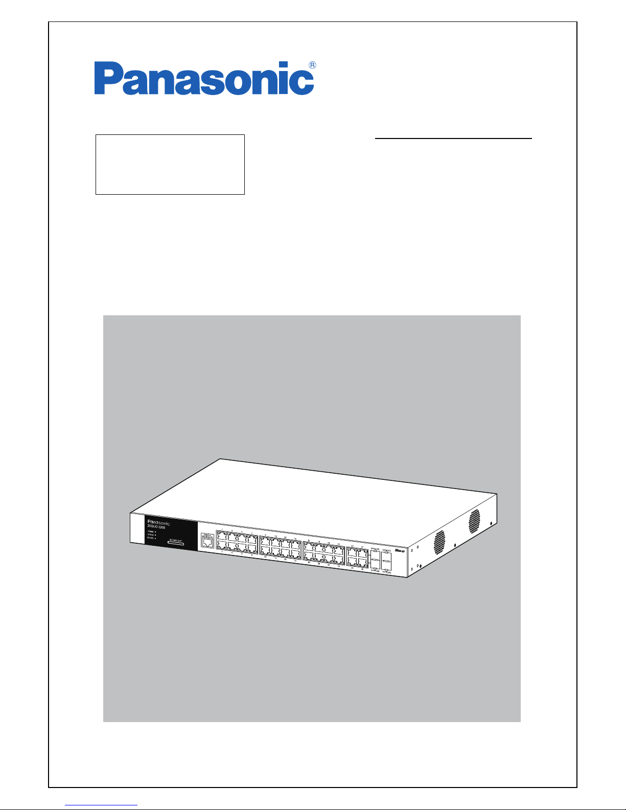
ZEQUO 2200
Model Number: PN26241
Thank you for purchasing our product.
This
manual provides important information about safe and proper
operations of this Switching Hub.
P
lease read "Important Safety Instructions" on pages 6 to 8 before use.
U
nder all circumstances, customer disassembling of this Switching Hub voids
the warranty.
2
The target model for this Operating Instruction is as follows.
Model name Model number Firmware version
ZEQUO 2200
PN26241-ID
1.0.0.20
PN26241-TH
PN26241-MY
PN26241-SG

3

4
Table of Contents
1. Product Outline ..................................................................................................... 11
2. Installation ............................................................................................................. 16
3. Connection ............................................................................................................ 17
4. Using Command Line Interface ............................................................................ 19
5. Basic Management Commands ............................................................................ 26
6. Access Control List (ACL) Commands ................................................................... 50
7. ARP Commands ..................................................................................................... 79
8. Asymmetric VLAN Commands .............................................................................. 87
9. Auto Configuration Commands ........................................................................... 90
10. Basic IP Commands ............................................................................................... 94
11. Bootup Function Commands .............................................................................. 104
12. BPDU Attack Protection Commands .................................................................. 107
13. Cable Diagnostics Commands ............................................................................. 113
14. Command List History Commands ...................................................................... 116
15. Command Logging Command List ..................................................................... 120
16. Network Access Authentication Command List ................................................. 123
17. Didital Diagnostic Monitoring (DDM) Commands ............................................. 132
18. Debug Software Command List .......................................................................... 150
19. DHCP Snooping Commands ............................................................................... 165
20. Domain Name System (DNS) Relay Commands ................................................. 170
21. DNS Resolver Commands .................................................................................... 176
22. Energy Efficient Ethernet (EEE) Commands ....................................................... 184
23. FDB Commands ................................................................................................... 186
24. File System Management Commands ................................................................ 197
25. Filter Commands ................................................................................................. 209
26. Gratuitous ARP Commands ................................................................................ 216
27. IGMP Snooping Commands ................................................................................ 223
28. IP Routing Commands ........................................................................................ 245
29. IP Source Address Verify Commands .................................................................. 250
30. IPv6 NDP Commands .......................................................................................... 264
31. Jumbo Frame Commands ................................................................................... 274
32. LACP Configuration Commands ......................................................................... 278
33. Layer 2 Protocol Tunneling (L2PT) Command List ............................................. 281
34. Limited Multicast IP Address Commands ........................................................... 286
35. Link Aggregation Commands ............................................................................. 296
36. LLDP Commands ................................................................................................. 302
37. Loopback Interface Commands .......................................................................... 331
38. MAC Notification Commands ............................................................................. 335
39. MAC-based Access Control Commands .............................................................. 340
40. Mirror Commands ............................................................................................... 362
41. MLD Snooping Commands ................................................................................. 369
42. Login Banner and Prompt Commands ............................................................... 390
43. Network Load Balancing (NLB) Commands ....................................................... 391
44. Network Management Commands .................................................................... 395
45. Network Monitoring Commands ........................................................................ 414

5
46. Packet Storm Commands .................................................................................... 436
47. Port Security Commands ..................................................................................... 442
48. Power Saving Commands ................................................................................... 452
49. Protocol VLAN Commands ................................................................................. 454
50. QoS Commands ................................................................................................... 462
51. Ring Redundant Protocol (RRP) Commands ...................................................... 484
52. RSPAN Commands .............................................................................................. 494
53. SNMPv1/v2/v3 Commands ................................................................................. 502
54. Spanning Tree Protocol (STP) commands .......................................................... 524
55. SSH Commands ................................................................................................... 541
56. Static MAC-based VLAN Commands .................................................................. 551
57. Subnet VLAN Commands .................................................................................... 555
58. Switch Port Commands ....................................................................................... 563
59. System Severity Commands ................................................................................ 569
60. Tech Support Commands .................................................................................... 571
61. Time and SNTP Commands ................................................................................. 574
62. Traffic Segmentation Commands ....................................................................... 582
63. Utility Commands ................................................................................................ 584
64. Voice VLAN Commands ...................................................................................... 613
65. VLAN Commands ................................................................................................ 624
66. VLAN Trunking Commands ................................................................................. 642
67. 802.1X Commands .............................................................................................. 647
68. Web-based Access Control (WAC) Commands ................................................... 681
69. System Log Lists .................................................................................................. 698
70. Appendix A. Specifications ................................................................................. 718
71. Appendix B. Procedures for Configuration Using ZEQUO assist Plus ................ 721
72. Appendix C. Private MIB Trap List ...................................................................... 722
73. Troubleshooting .................................................................................................. 723
74. Warranty and After-sales Service ........................................................................ 725

Important Safety Instructions
6
This chapter contains important safety instructions for preventing bodily
injury and/or property damage. You are required to follow them.
■Severity of bodily injury and/or property damage, which could result
from
incorrect use of the Switching Hub, are explained below.
This symbol indicates a potential hazard that
could result in serious injury or death.
This symbol indicates safety instructions.
Deviation from these instructions could lead to
bodily injury and/or property damage.
■The following symbols are used to classify and describe the type of
instructions to be observed.
This symbol is used to alert users
to what they must not do.
This symbol is used to alert users
to what they must do.
●Do not use power supply other than AC 100 - 240 V.
Deviation could lead to fire, electric shock, and/or equipment fa
ilure.
●Do not handle the power cord with wet hand.
Deviation could lead to electric shock, and/or equipment failure.
●Do not handle this Switching Hub and connection cables during a
thu
nderstorm.
Deviation could lead t
o electric shock.
●Do not disassemble and/or modify this Switching Hub.
Deviation could lead to fire, electric shock, and/or equipment fa
ilure.
●Do not damage the power cord. Do not bend too tightly, stretch,
twist, bundle with other cord, pinch, put under a heavy object,
and/or heat it.
A damaged power cord could lead to fire, short, and/or electric
sho
ck.
●Do not put foreign objects (such as metal or combustibles) into the
opening (such as twisted pair port, console port, SFP extension slot,
S
FP+ extension slot, or SD card slot), and/or do not drop them into
the
inside of the Switching Hub.
Deviation could lead to fire, electric
shock, and/or equipment
failure.
●Do not connect equipments other than 10BASE-T/100BASE-TX/
1000BASE-T to twisted pair port.
Deviation could lead to fire, electric
shock, and/or equipment
failure.
●Do not place this Switching Hub in harsh environment such as near
water, high humid, and/or high dust.
Deviation could lead to fire, electric
shock, and/or equipment
failure.
●Do not place this Switching Hub under direct sun light and/or high
temperature.
Deviation could lead to high inter
nal temperature and fire.
●Do not install this Switching Hub at the location with continuous
v
ibration or strong shock, or at an unstable location.
Deviation could lead to injury and/or equipment failure.
●Do not install any module other than our optional SFP modules
(PN
54021K/PN54023K) to SFP exstension slot.
Deviation could lead to fire, electric shock, and/or equipment failure.
●Do not put this Switching Hub into fire.
Deviation could lead to explosion and/or fire.
●Do not use the supplied power cord for anything other than this
pr
oduct.
Deviation could lead to fire, electric shock, and/or equipment failure.
7
●Use the bundled power cord (AC 100 - 240 V specifications).
Deviation could lead to electric shock, malfunction, and/or equipment
failure.
●Unplug the power cord in case of equipment failure.
Deviation, such as keeping connected for a long time, could lead
to
fire.
●Connect this Switching Hub to ground.
Deviation could lead to electric shock, malfunction, and/or equipment
failure.
●Connect the power cord firmly to the power port.
Deviation could lead t
o electric shock, and/or malfunction.
●Unplug the power plug if the STATUS LED blinks in orange (system
fault).
Deviation, such as keeping connected for a long time, could lead to
fire.
●Handle the Switching Hub carefully so that fingers or hands may
not
be damaged by twisted pair ports, SFP extension slots, console
port, SD card slot, or power cord hook block.
8

Basic Instructions for the Use of This Product
●For internal inspection and/or repair, please contact the shop.
●Use commercial power supply from
a wall socket, which is close and easily
accessible to this Switching Hub.
●Unplug the power cord when installing or moving this Switching Hub.
●Unplug the power cord when cleaning this Switching Hub.
●Use this Switching Hub within the specifications. Deviation cou
ld lead to
malfunctions.
●Do not touch the metal terminal of the RJ45 connector, the modular plug
of
connected twisted pair cable and serial port, or the metal terminal of the
SFP extension slot. Do not place charged objects in the proximity of them.
Static electricity could lead to equipment failure.
●Do not put the modular plug of the connected twisted pair cable on objects
that
can carry static charge, such as a carpet. Do not place it in the proxim-
ity. Static electricity could lead to equipmen
t failure.
●Before connecting a console cable to the console port, discharge
static elec-
tricity, for example by touching metal appliance (do not dischar
ge by
touching this Switching Hub).
●Do not put a strong shock, including dropping, to this Switching Hub.
Deviation could lead to equipment failure.
●Do not store and/or use this Switching Hub in the environment with the
characteristics listed below.
(Store and/or use this Switching Hub in the environment in accordance with the
specifica
tion.)
- High humidity. Possible spilled liquid (water).
- Dusty. Possible static charge (such as carpet).
- Under direct sunlight.
- Possible condensation. High/low temperature exceeding the
environment specifications.
- Strong vibration and/or strong shock.
●Please use this Switching Hub in place where ambient temperatur
e is from
0 to 50 degrees C. Failure to meet the above conditions may result in fire,
electric shock, breakdown, and/or malfunction. Please take notice because
such cases are out of guarantee. Additionally, do not cover the bent hole of
this Switching Hub.
Deviation could lead to high internal temperature, equipment failure
and/or
malfunction.
●When stacking Switching Hubs, leave
a minimum of 20 mm space between
them.
●Please note that operation will
not be guaranteed if any SD card other than
the separately sold Panasonic SD card is installed into the SD card slot.
Format the card with this Switching Hub.
9

10
1. Panasonic will not be liable for any damage resulting from the operation not
in accordance with this operation manual or loss of communications, which
may or may not be caused by failure and/or malfunction of this
product.
2. The contents described in this document may be changed without prior
notice.
The latest version is available on our web site.
3. For any questions, please contact the shop where you purchased the product.
* Brands and product names in this document are trademarks or registered
trademarks of their respective holders.

1. Product Outline
11
1. Product Outline
ZEQUO 2200 is a Layer-2 all Gigabit Ethernet Switching Hub with man-
agement functions, equipped with 28 10/100/1000BASE-T ports and 4
1000BASE-X SFP extension slots.
1.1. Features
Ports 1 to 28 (copper ports) are 10BASE-T/100BASE-TX/1000BASE-T ports corre-
sponding to auto negotiation.
Ports 25 to 28 are not support the half-duplex mode.
Ports 25 to 28 also have SFP extension ports as combo ports. You can select either
of 1000BASE-T supported copper port or SFP port for use.
An SD card can be used to change and save configuration and firmware.
All copper ports support the straight/cross cable via auto sensing function.
You can simply connect devices with straight cables, whether the target is a terminal or
a network device.
The Power Saving Mode detects the connection status automatically and saves power
consumption to minimum.
The Energy Efficient Ethernet (IEEE802.3az LPI) is supported, allowing to reduce
power consumption at link-up ports.
The auto negotiation function is supported, allowing to easily support a heteroge-
neous environment of 10BASE-T, 100BASE-TX, and 1000BASE-T. The speed and com-
munication mode can be set at Fixed.
The Ping command can be used to verify communications.
The standard MIB (MIB II, Bridge MIB, RMON four groups, etc.) is supported, allowing
to manage the Switching Hub from the SNMP manager. (For details, refer to Appendix
A.)
The support application “ZEQUO assist Plus” supports GUI-based easy configura-
tion for installation.
The Access Control function is supported, allowing to filter by IP address, MAC
address, protocol number, and L4 port number.
Spanning Tree Protocol is supported, allowing to build a redundant system.
IEEE802.1Q tagged VLAN is supported, allowing to register up to 4094 VLANs.
The IEEE802.1p QoS function is supported.
The IEEE802.3ad Link Aggregation function is supported, allowing to configure up to 8
ports and 32 groups.

1. Product Outline
12
The IEEE802.1X authentication function is supported, allowing to block network access
from unregistered users.
The IGMP Snooping function is supported, allowing to prevent multicast packets
from monopolizing bandwidth.
The Ring Redundant Protocol (RRP) is supported, allowing to make a redundant
network via ring topology.
1.2. Accessories
Please be sure to confirm the contents. Please contact your distributor if any of the con-
tents are insufficient.
ZEQUO 2200 main unit...................................................................1
Installation Guide............................................................................1
CD-ROM (including this Operating Instructions)............................1
Mounting brackets (for 19-inch rack mount).................................2
Screws (for 19-inch rack mount).....................................................4
Screws (for fixing the main unit and the mounting bracket).........8
Rubber foot.....................................................................................4
Dummy SD card...............................................................................1
Power cord (*).................................................................................1
(*) The attached power cord is dedicated for AC 100 - 240 V use.
1.3. Optional Accessories
PN54021K 1000BASE-SX SFP Module
PN54023K 1000BASE-LX SFP Module
1. Product Outline
13
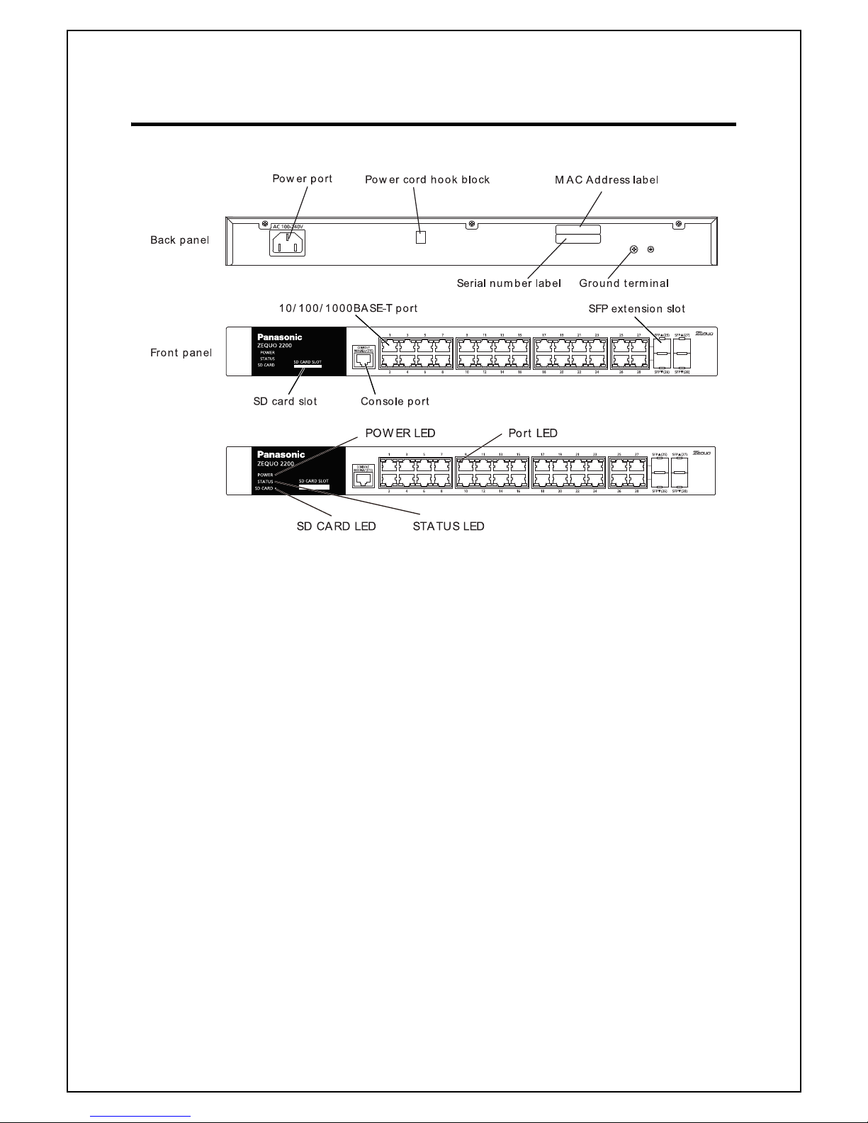
1.4. Part Names and Functions
Fig. 1-1 Back, Front, LEDs
● Power port
Connect the supplied power cord into the port and connect the other end into an
electric outlet.
● Power cord hook block
Hooking the supplied power cord on the block makes the cord less likely to be
unplugged from the power port.
●Ground terminal
Connect the earth terminal screw and grounding surface using the earth wire.
●SD card slot
Insert a SD card to change configuration information and change and save firm-
ware.
● 10BASE-T/100BASE-TX/1000BASE-T port (Ports 1 to 28)
Connect a 10BASE-T/100BASE-TX/1000BASE-T terminal hub repeater Switching
Hub. The length of the copper cabling (CAT5e or higher) connecting this Switching
Hub and a device must be 100 m or shorter.

1. Product Outline
14
● 10BASE-T/100BASE-TX/1000BASE-T port (Ports 25 to 28)
Connect a 10BASE-T/100BASE-TX/1000BASE-T terminal hub repeater Switching
Hub. The length of the copper cabling (CAT5e or higher) connecting
this Switching
Hub
and a device must be 100 m or shorter.
Ports 25 - 28 are not supported half-duplex mode.
● SFP extension port (Ports 25 to 28)
Install an SFP module. (These ports are exclusive usage with twisted pair ports.)
When SFP extension port is linked, the port is automatically switched to fiber port
mode. SFP extension ports support only the full-duplex mode.
●Console port
Used to connect a VT100 compatible terminal to configure and manage this
Switching Hub.
Transmission mode : RS-232C Emulation mode : VT100
Transmission speed : 9,600 bps Data length : 8 bits
Stop bit : 1 bit Parity control : None
Flow control : None Communication connector : RJ45
Use an RJ45-Dsub 9 pin console cable for connection.
1.5. LED Behavior
1.5.1. LED Behavior at Starting-up
When you turn on this Switching Hub, all LEDs are lit momentarily. POWER LED lights
green and STATUS LED lights orange, and then the hardware self diagnosis is exe
-
cuted. Upon finishing the diagnosis, both POWER and STATUS LEDs light green.
1.5.2. LED Behavior while Operating
This Switching Hub has a set of LEDs for each port. These LEDs indicate the operation
status of each port.

1. Product Outline
15
●System LED
LED Behavior Description
POWR LED Green Light Power is ON
Off Power is OFF
STATUS LED Green Light The system is operating nor-
mally.
Orange Light The system is staring up.
Orange Blink Malfunction
(Contact the shop)
SD CARD LED Green Light SD card is inserted
Green Blink Accessing to SD card
Orange Light SD card error
Off Not inserted
● 10/100/1000BASE-T port LED (Ports 1 to 28)
LED Behavior Description
LINK/ACT. Green Light 1000Mbps link established in full-duplex.
Green Blink Transmitting/receiving packets in 1000Mbps
full-duplex.
Orange Light 10/100Mbps link established.
Orange Blink Transmitting/receiving packets at 10/
100Mbps.
Off No device connected.
●SFP extension slot LED (Ports 25 to 28)
LED Behavior Description
LINK/ACT. Green Light 1000Mbps link established in full-duplex.
Green Blink Transmitting/receiving packets in 1000Mbps
fu
ll-duplex.
Off No device connected.
2. Installation
16
2. Installation
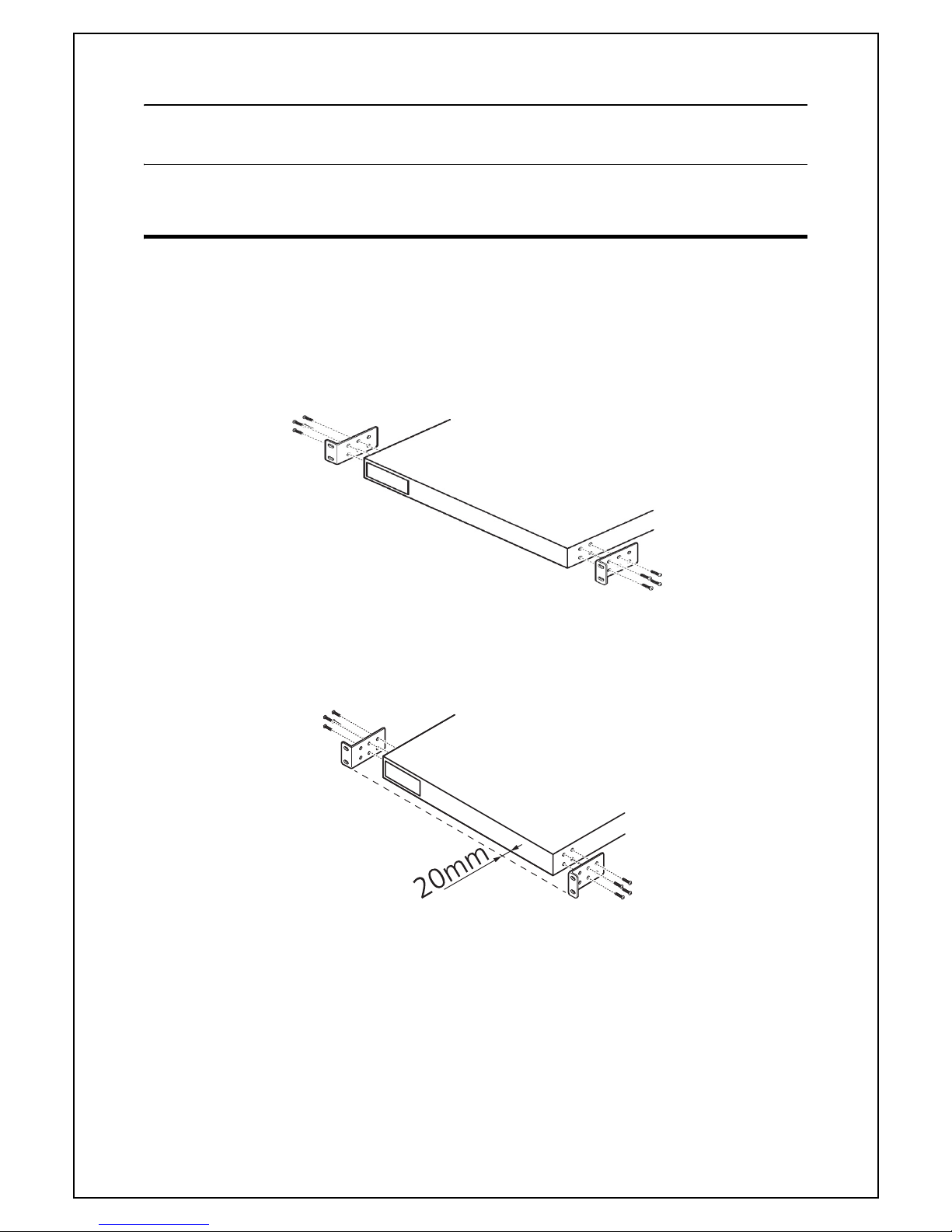
2.1. Installing in a 19-inch Rack
Take out two mount brackets and eight screws (for securing the mount brackets to
the Switching Hub) from accessories, and secure a bracket to each of the right an
d
left sides of the Switching Hub via four screw holes.
Then, by using four supplied screws (for 19-inch rack mount) or
screws included with
the rack, firmly mount the Switching Hub in the rack.
Fig. 2-1 Installing in 19-inch Rack
The main unit can be placed 20 mm back on the
rack by changing the bracket fixing
position.
Fig. 2-2 Installing in 19-inch Rack (20 mm backword mounting)
3. Connection
17
3. Connection
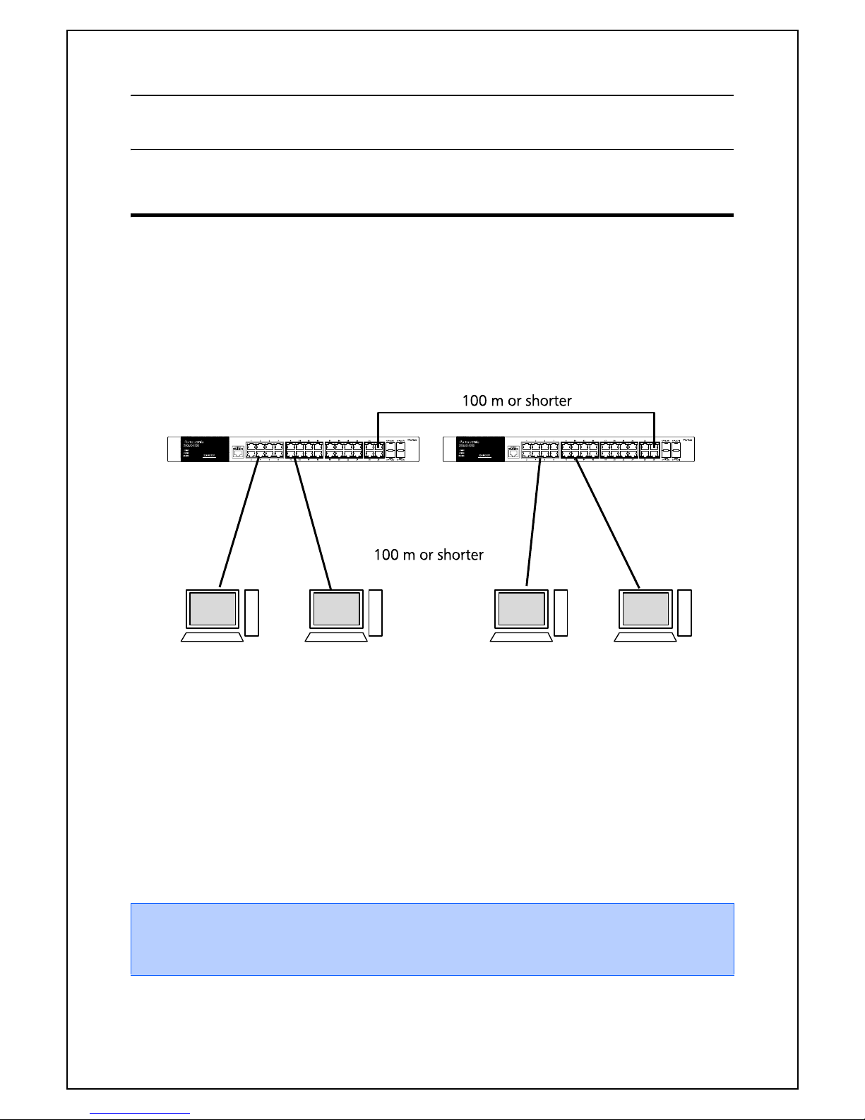
3.1. Connecting a Copper Cable Port
● Connection Cable
Use a CAT5e or higher compliant straight cable (copper cabling) with 8P8C RJ45 mod-
ular plugs.
● Network Configuration
Fig. 3-1 Connection Configuration Example
The length of the cable connecting this Switching Hub and a device must be 100 m or
s
horter. When a terminal or a LAN device with auto negotiation function is connected
to a port, the port is automatically configured to the most appropriate performance
mode. When a terminal or a device without auto negotiation function is connected to
a port, this Switching Hub automatically determines and sets the communication
speed;
however, the full/half-duplex configuration is set at half-duplex because the
full/half-duplex capability cannot be determined. When connecting a terminal or a
device without auto negotiation function, set the connection mode of the port to
Fixed.
Note: If connection mode is set to a fixed value, Auto MDI/MDI-X function does not
work. Therefore, you need to use a cross cable for connections between
Switching Hubs.
3. Connection
18
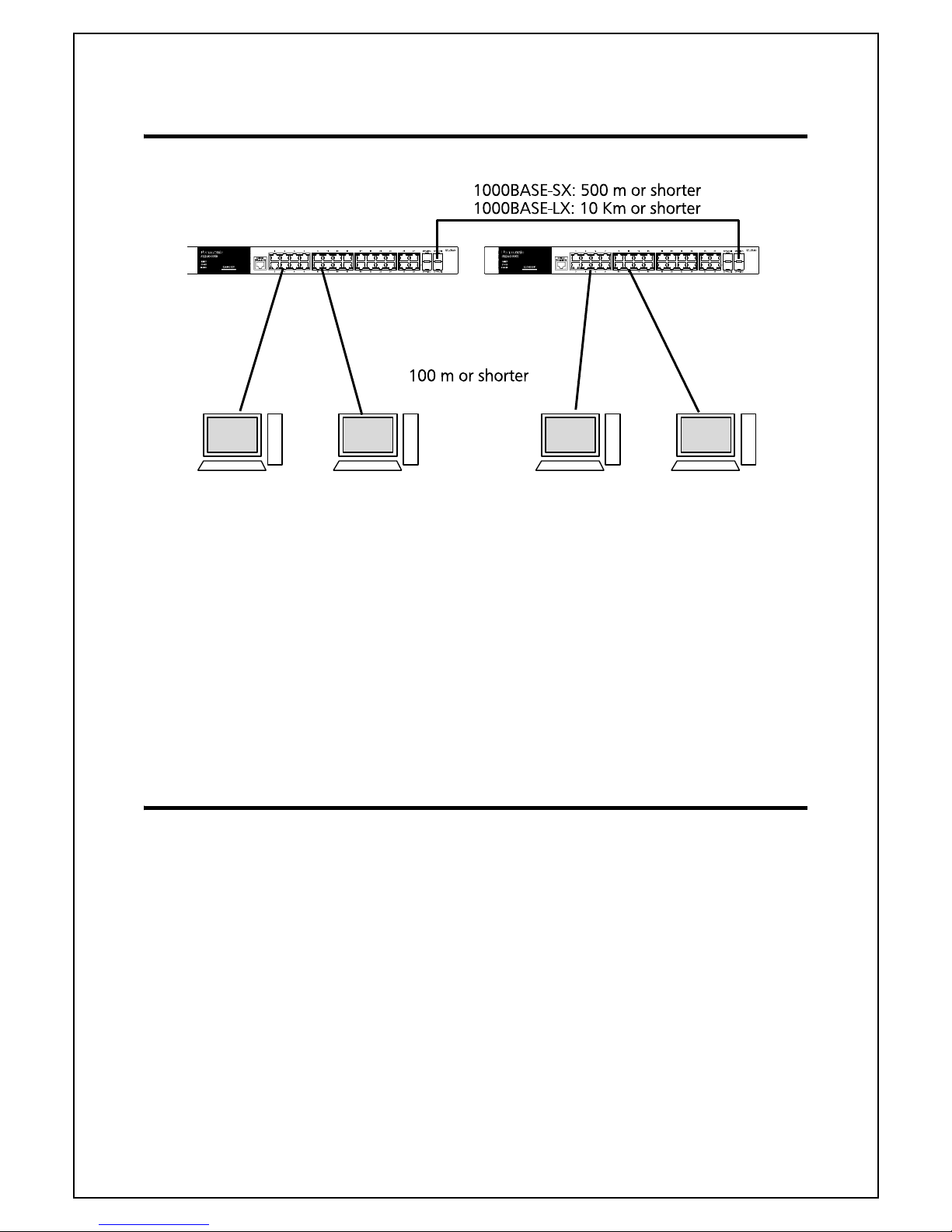
3.2. Connecting with an SFP Extension Slot
Fig. 3-2 Optical Fiber Cable Connection Example
Plugging an SFP module (optional) into an SFP extension slot enables an optical fiber
c
onnection. By factory default, the copper cable port is enabled, but the SFP extension port is automatically enabled when a link is established.
Connect this Switching Hub's TX port to the RX port of
the connected device and this
Switching Hub's RX port to the TX port of the connected device.
The following SFP modules are optionally available:
- 1000BASE-SX SFP module (Part number: PN54021K)
- 1000BASE-LX SFP module (Part number: PN54023K)
3.3. Connecting to Power
Connect the supplied power cord to the power port of this Switching Hub, and con-
nect the power plug into an electric outlet. The Switching Hub operates at AC 100 -
240 V
(50/60 Hz).
It does not have a power switch. When you connect the power plug,
the Switching
Hub turns on and starts operating. To power off, unplug the power p
lug from the
electric outlet.

4. Using Command Line Interface
19
4. Using Command Line Interface
The Command Line Interface (CLI) is an operation screen to configure and
manage this Switching Hub.
You can use the CLI by connecting a VT-100 compatible terminal to the
serial port of this Switching Hub or through a remote connection such as
telnet.
This chapter describes the following CLI procedures.
Overview of connecting to the serial port
How to configure the IP address of this Switching Hub
Overview of how to use commands
- "?" command, which displays the command help
- Operations when parameters are omitted
- Using command autocomplete function and input history
- Operations when making a typo
Syntax rules
Available input editing keys and page operation keys
4.1. Accessing the Switching Hub via the
Serial Port
The Switch's serial port's default settings are as follows:
9600 baud
no parity
8 data bits
1 stop bit
A computer running a terminal emulation program capable of emulating a VT-100 terminal
and a serial port configured as above is then connected to the Switch
ing Hub's serial
port via an RJ-45 to RS-232 DB-9 convertor cable.
With the serial port properly connected to a management computer, the following screen
should be visible.
Zxxx0 Gigabit Ethernet Switch
Command Line Interface
Firmware: Build 1.0.x.xx
UserName:

4. Using Command Line Interface
20
There is no initial username or password. Just press the Enter key twice to display the CLI
input cursor
- Zxxx0:admin#. This is the command line where all commands are input.
4.2. Setting the Switching Hub's IP Address
Each Switching Hub must be assigned its own IP Address, which is used for
communication with an SNMP network manager or other TCP/IP application (for
example BOOTP, TFTP). The Switch's default IP address is 10.90.90.90. You can
change the default Switch IP address to meet the specification of your networking
address scheme.
The Switching Hub is also assigned a unique MAC address by the factory. This MAC
address cannot be changed, and can be found on the initial boot console screen
-
shown below or the command show switch.
The Switching Hub's MAC address can also be found in the Web management
program on the Device Information (Basic Settings) window on the Configuration
menu.
The IP address for the Switching Hub must be set before it can be managed with the
Web-based manager. The Switch IP address can be automatically set using BOOTP or
DHCP protocols, in which case the actual address assigned to the Switch
ing Hub must
be known.
Starting at the command line prompt, enter the commands config ipif System ipaddress
xxx.xxx.xxx.xxx/yyy.yyy.yyy.yyy. Where the x's represent the IP address to be assigned to the
IP interface named System and the y's represent the corresponding subnet mask.
Alternatively, you can enter config ipif System ipaddress xxx.xxx.xxx.xxx/z. Where the x's
represent the IP address to be assigned to the IP interface named System and the z
represents the corresponding number of subnets in CIDR notation.
The IP interface named System on the Switch can be assigned an IP address and subnet
mask which can then be used to connect a management station to the Switch
ing
Hub
's Telnet agent.
Boot Procedure V1.0.x.xx
-------------------------------------------------------------------------------
Power On Self Test ........................................ 100 %
MAC Address : 00-01-02-03-04-00
H/W Version : A1
Please Wait, Loading V1.0.x.xx Runtime Image .............. 100 %
UART init ................................................. 100 %
Starting runtime image
Device Discovery .......................................... 100 %
Configuration init ........................................ 100 %

4. Using Command Line Interface
21
In the above example, the Switching Hub was assigned an IP address of 10.24.22.100
with a subnet mask of 255.0.0.0. The system message Success indicates that the
command was executed successfully. The Switch can now be configured and
managed via Telnet, SNMP MIB browser and the CLI or via the Web-based
management agent using the above IP address to connect to the Switch
ing Hub.
There are a number of helpful features included in the CLI. Entering the ? command will
display a list of all of the top-level commands.
When entering a command without its required parameters, the CLI will prompt you with a
Next possible completions: message.
In this case, the command config account was entered with the parameter <username>.
The CLI will then prompt to enter the <username> with the message, Next possible
completions:. Every command in the CLI has this feature, and complex commands have
several layers of parameter prompting.
In addition, after typing any given command plus one space, users can see all of the next
possible sub-commands, in sequential order, by repeatedly pressing the Tab key.
Zxxx0:admin# config ipif System ipaddress 10.24.22.100/255.0.0.0
Command: config ipif System ipaddress 10.24.22.100/8
Success.
Zxxx0:admin#
Zxxx0:admin#?
Command: ?
..
?
cable_diag ports
cd
change drive
clear
clear address_binding dhcp_snoop binding_entry ports
clear address_binding nd_snoop binding_entry ports
clear arptable
clear attack_log
clear counters
clear dhcp binding
clear dhcp conflict_ip
clear dhcpv6 binding
CTRL+C ESC q Quit SPACE n Next Page ENTER Next Entry a All
Zxxx0:admin#config account
Command: config account
Next possible completions:
<username>
Zxxx0:admin#

4. Using Command Line Interface
22
To re-enter the previous command at the command prompt, press the up arrow cursor key.
The previous command will appear at the command prompt.
In the above example, the command config account was entered without the required
parameter <username>, the CLI returned the Next possible completions: <username>
prompt. The up arrow cursor control key was pressed to re-enter the previous command
(config account) at the command prompt. Now the appropriate username can be entered
and the config account command re-executed.
All commands in the CLI function in this way. In addition, the syntax of the help prompts
are the same as presented in this manual - angle brackets < > indicate a numerical value or
character string, braces { } indicate optional parameters or a choice of parameters, and
brackets [ ] indicate required parameters.
If a command is entered that is unrecognized by the CLI, the top-level commands will be
displayed under the Available commands: prompt.
The top-level commands consist of commands such as show or config. Most of these
commands require one or more parameters to narrow the top-level command. This is
equivalent to show what? or config what? Where the what? is the next parameter.
For example, entering the show command with no additional parameters, the CLI will then
display all of the possible next parameters.
Zxxx0:admin# config account
Command: config account
Next possible completions:
<username>
Zxxx0:admin# config account
Zxxx0:admin#the
Available commands:
.. ? cable_diag cd
change clear config
copy create debug del
delete dir disable download
enable erase format login
logout md move no
ping ping6 rd reboot
reconfig rename reset save
show telnet traceroute traceroute6
upload
Zxxx0:admin#

4. Using Command Line Interface
23
In the above example, all of the possible next parameters for the show command are
displayed. At the next command prompt, the up arrow was used to re-enter the show
command, followed by the account parameter. The CLI then displays the user
accounts configured on the Switch.
Zxxx0:admin#show
Command: show
Next possible completions:
802.1p 802.1x access_profile account
accounting acct_client arpentry asymmetric_vlan
attack_log auth_client auth_diagnostics
auth_session_statistics auth_statistics authen
authen_enable authen_login authen_policy authentication
authorization autoconfig bandwidth_control boot_file
bpdu_protection broadcast_ping_reply command
command_history community_encryption config
current_config ddm device_status dhcp_snoop
dnsr dot1v_protocol_group dscp
egress_access_profile egress_flow_meter environment
error fdb filter flow_meter
gratuitous_arp gvrp hol_prevention host_name
igmp_snooping ip_source_binding ip_verify_source ipif
ipif_ipv6_link_local_auto iproute ipv6
ipv6route jumbo_frame l2protocol_tunnel lacp_port
limited_multicast_addr link_aggregation lldp
lldp_med log log_save_timing
log_software_module loopback
mac_based_access_control mac_based_access_control_local
mac_based_vlan mac_notification max_mcast_group
mcast_filter_profile mirror mld_snooping
multicast multicast_fdb name_server nlb
packet per_queue port port_group
port_security port_security_entry port_vlan
ports power_saving private_vlan ptp
radius rcp rmon router_ports
rspan scheduling scheduling_mechanism
serial_port session snmp sntp
ssh stack_device stack_information stacking_mode
storage_media_info stp subnet_vlan
switch syslog system_severity tech_support
terminal time time_range traffic
traffic_segmentation trap trusted_host
utilization vlan vlan_precedence vlan_trunk
voice_vlan wac
Zxxx0:admin#

4. Using Command Line Interface
24
4.3. Command Syntax Symbols
The following symbols are used to describe how command entries are made and
values and arguments are specified in this manual. The online help contained in the
CLI and available through the console interface uses the same syntax.
All commands are case-sensitive. Be sure to disable Caps Lock or any other
unwanted function that changes text case.
Syntax Description
angle brackets < > Encloses a variable or value. Users must specify the variable or value. For
example, in the syntax
create ipif <ipif_name 12> {<network_address>} <vlan_name 32>
{secondary | state [enable | disable] | proxy_arp [enable | disable] {local
[enable | disable]}}
users must supply an IP interface name for <ipif_name 12> and a VLAN
name for <vlan_name 32> when entering the command. DO NOT TYPE THE
ANGLE BRACKETS.
square brackets [ ] Encloses a required value or list of required arguments. Only one value or
argument must be specified. For example, in the syntax
create account [admin | operator | power_user | user] <username 15>
{encrypt [plain_text | sha_1] <password>}
users must specify either the admin-, operator-, power_user-level or user-
level account when entering the command. DO NOT TYPE THE SQUARE
BRACKETS.
vertical bar | Separates mutually exclusive items in a list. For example, in the syntax
reset {[config |system]} {force_agree}
users may choose config or system in the command. DO NOT TYPE THE
VERTICAL BAR.
braces { } Encloses an optional value or a list of optional arguments. One or more
values or arguments can be specified. For example, in the syntax
config dhcp_relay {hops <int 1-16> | time <sec 0-65535>}(1)
users may choose config or system in the command. DO NOT TYPE THE
BRACES.
parentheses ( ) Indicates at least one or more of the values or arguments in the preceding
syntax enclosed by braces must be specified. For example, in the syntax
config dhcp_relay {hops <int 1-16> | time <sec 0-65535>}(1)
users have the option to specify hops or time or both of them. The "(1)"
following the set of braces indicates at least one argument or value within
the braces must be specified. DO NOT TYPE THE PARENTHESES.
ipif <ipif_name 12>
metric <value 1-31>
12 means the maximum length of the IP interface name.
1-31 means the legal range of the metric value.
ワヰヵユ
ワヰヵ
ユ

4. Using Command Line Interface
25
4.4. Line Editing Keys
The screen display pauses when the show command output reaches the end of the
page.
4.5. Multiple Page Display Control Keys
Keys Description
Delete Delete character under cursor and shift remainder of line to left.
Backspace Delete character to left of cursor and shift remainder of line to left.
Ctrl+R Toggle on and off. When toggled on, inserts text and shifts previous text to
right.
Up Arrow Repeats the previously entered command. Each time the up arrow is pressed,
the command previous to that displayed appears. This way it is possible to
review the command history for the current session. Use the down arrow to
progress sequentially forward through the command history list.
Down Arrow The down arrow will display the next command in the command history
entered in the current session. This displays each command sequentially as it
was entered. Use the up arrow to review previous commands.
Left Arrow Move cursor to left.
Right Arrow Move cursor to right
Tab Help user to select appropriate token.
Keys Description
Space Displays the next page.
Ctrl+C Stops the display of remaining pages when multiple pages are to be
displayed.
Esc Stops the display of remaining pages when multiple pages are to be
displayed.
n Displays the next page.
p Displays the previous page.
q Stops the display of remaining pages when multiple pages are to be
displayed.
r Refreshes the pages currently displayed.
a Displays the remaining pages without pausing between pages.
Enter Displays the next line or table entry.

5. Basic Management Commands
26
5. Basic Management Commands
This chapter describes the basic management commands for this Switching
Hub.
Creating, editing, displaying, and deleting the accounts of users to manage this
Switching Hub
Up to eight user accounts can be created.
Encrypting the login password and configuration file
Displaying users who are currently logged in to the console
Displaying and managing the status of power, temperature, and fan on this Switching
Hub
Configuring the serial port (serial port) setting
Pausing the screen page feed, configuring the terminal width, and clearing the screen
Using Telnet
Saving configuration and log files to NV-RAM
Resetting and rebooting
Logging in and logging out
create account [admin | operator | power_user | user] <username 15> {encrypt [plain_text |
sha_1] <password>}
config account <username> {encrypt [plain_text | sha_1] <password>}
show account
delete account <username>
show session
show switch
show environment
config temperature [trap | log] state [enable | disable]
config temperature threshold {high <temperature -500-500> | low <temperature -500-500>}(1)
show serial_port
config serial_port {baud_rate [9600 | 19200 | 38400 | 115200] | auto_logout [never |
2_minutes | 5_minutes | 10_minutes | 15_minutes]}(1)
enable clipaging
disable clipaging
enable telnet {<tcp_port_number 1-65535>}
disable telnet
save {[config <pathname> | log | all]}
reboot {force_agree}
reset {[config | system]} {force_agree}
login
logout
clear
config terminal width [default | <value 80-200>]
show terminal width
show device_status
ワヰヵユ
ワヰヵ
ユ

5. Basic Management Commands
27
5.1. create account
Description
This command creates user accounts. The username is between 1 and 15 characters, the
password is between 0 and 15 characters. The number of accounts (including admin,
operator, and user) is up to eight.
Format
create account [admin | operator | power_user | user] <username 15> {encrypt [plain_text
| sha_1] <password>}
Parameters
Restrictions
Only Administrator-level users can issue this command.
admin Specify the name of the admin account.
operatorSpecify the name of the operator account.
power_user
Specify a power user level account. The power user level is lower than the operator level
and higher than the user level.
user Specify the name of the user account.
<username 15>
Specify a username of up to 15 characters.
encrypt (Optional)Specifies the encryption used.
plain_text
Specify the password in plain text form.
sha_1Specify the password in SHA-1 encrypted form.
<password>
The password for the user account. The length of a password in plain-text form and
encrypted form are different. For a plain-text form password, the password must
be a minimum of 0 characters and a maximum of 15 characters. For an encrypted
form password, the length is fixed to 35 bytes long. The password is case-sensitive.

5. Basic Management Commands
28
Example
To create the Administrator-level user "panasonic":
To create the Operator-level user "Sales":
To create the User-level user "System":
Zxxx0:admin#create account admin manager
Command: create account admin manager
Enter a case-sensitive new password:****
Enter the new password again for confirmation:****
Success.
Zxxx0:admin#
Zxxx0:admin##create account operator Sales
Command: create account operator Sales
Enter a case-sensitive new password:****
Enter the new password again for confirmation:****
Success.
Zxxx0:admin#
Zxxx0:admin##create account user System
Command: create account user System
Enter a case-sensitive new password:****
Enter the new password again for confirmation:****
Success.
Zxxx0:admin#

5. Basic Management Commands
29
5.2. enable password encryption
Description
The user account configuration information will be stored in the configuration file,
and can be applied to the system later. If the password encryption is enabled, the
password will be in encrypted form when it is stored in the configuration file. When
password encryption is disabled, the password will be in plain text form when it is
stored in the configuration file. However, if the created user account directly uses the
encrypted password, the password will still be in the encrypted form.
Format
enable password encryption
Parameters
None.
Restrictions
Only Administrator-level users can issue this command.
Example
To enable password encryption:
5.3. disable password encryption
Description
The user account configuration information will be stored in the configuration file,
and can be applied to the system later. If the password encryption is enabled, the
password will be in encrypted form when it is stored in the configuration file. When
password encryption is disabled, the password will be in plain text form when it is
stored in the configuration file. However, if the created user account directly uses the
encrypted password, the password will still be in the encrypted form.
Format
disable password encryption
Zxxx0:admin#enable password encryption
Command: enable password encryption
Success.
Zxxx0:admin#

5. Basic Management Commands
30
Parameters
None.
Restrictions
Only Administrator-level users can issue this command.
Example
To disable password encryption:
Zxxx0:admin#disable password encryption
Command: disable password encryption
Success.
Zxxx0:admin#
 Loading...