

Page 1

SPECIFICATIONS
WV-CK1420
Power Source : 220 - 240V AC, 50Hz
Power Consumption : Approx. 66W
Screen Size : 371.8mm diagonal tube screen size, 90° deflection
335.4mm diagonal actual visual size
Horizontal Resolution : 330TV lines at centre
Video Input : 1.0V[p-p] composite/75Ω, BNC with Auto Termination
Audio Input : –8dB/Hi-z, RCA standard jack
Speaker Output : 0.7W
Sweep Linearity : Horizontal: Less than 5%
Vertical: Less than 5%
Sweep Geometry : Less than 2%
Ambient Operating Humidity : Less than 90%
Ambient Operating Temperature : –10°C - +50°C (14°F - 122°F)
Dimensions : 366(W) x 346(H) x 365(D)mm [14-7/16”(W) x 13-10/16”(H) x 14-6/16”(D)]
Weight : 9.6kg (21.2lbs.)
WV-CK2020
Power Source : 220 - 240V AC, 50Hz
Power Consumption : Approx. 80W
Screen Size : 548mm diagonal tube screen size, 90° deflection
508mm diagonal actual visual size
Horizontal Resolution : 500TV lines at centre
Video Input : 1.0V[p-p] composite/75Ω, BNC with Auto Termination
WV-CK1420/WV-CK2020
ORDER NO. AVS9911206C8
C 1999 Matsushita Communication Industrial Co., Ltd.
All rights reserved. Unauthorized copying and
distribution is a violation of law.
Colour Monitor
WV-CK1420 WV-CK2020
Page 2

This service information is designed for experienced repair technicians only and is not designed for use by the
general public.
It does not contain warnings or cautions to advise non-technical individuals of potential dangers in attempting to
service a product.
Products powered by electricity should be serviced or repaired only by experienced professional technicians. Any
attempt to service or repair the product or products dealt with in this service information by anyone else could
result in serious injury or death.
Y
WARNING
CAUTION
RISK OF ELECTRIC SHOCK
DO NOT OPEN
CAUTION:
TO REDUCE THE RISK OF ELECTRIC SHOCK,
DO NOT REMOVE COVER (OR BACK). NO USER
SERVICEABLE PARTS INSIDE.
REFER SERVICING TO QUALIFIED SERVICE
PERSONNEL.
This symbol warns the user that uninsulated voltage within
the unit may have sufficient magnitude to cause electric
shock. Therefore, it is dangerous to make any kind of contact
with any inside part of this unit.
This symbol alerts the user that important literature concerning
the operation and maintenance of this has been included.
Therefore, it should be read carefully in order to avoid
any problems.
There are special components used in this equipment which are important for safety. These parts are indicated
by the ” ” mark on the schematic diagram and the replacement parts list. It is essential that these critical
parts should be replaced with manufacturer's specified parts to prevent X-radiation, shock, fire, or other hazards.
Do not modify the original design without permission of manufacture.
IMPORTANT SAFETY NOTICE
Audio Input : –8dB/Hi-z, RCA standard jack
Speaker Output : 0.7W
Sweep Linearity : Horizontal: Less than 5%
Vertical: Less than 5%
Sweep Geometry : Less than 2%
Ambient Operating Humidity : Less than 90%
Ambient Operating Temperature : –10°C - +50°C (14°F - 122°F)
Dimensions : 509(W) x 467(H) x 480(D)mm [20-1/16”(W) x 18-6/16”(H) x 18-14/16”(D)]
Weight : 21kg (46.3lbs.)
Weights and dimensions shown are approximate.
Specifications are subject to change without notice.
CONTENTS
Major Operating Controls and Their Functions . . . . . . . . . . . . . . . . . . . . . . . . . . . . . . . . . . . . . . . . . . . . . . . . . . . . . . . . . . . . . . 1
Adjustment Procedure . . . . . . . . . . . . . . . . . . . . . . . . . . . . . . . . . . . . . . . . . . . . . . . . . . . . . . . . . . . . . . . . . . . . . . . . . . . . . . . . . . 3
Location of Test Points and Adjusting Controls . . . . . . . . . . . . . . . . . . . . . . . . . . . . . . . . . . . . . . . . . . . . . . . . . . . . . . . . . . . . . 9
Block Diagram . . . . . . . . . . . . . . . . . . . . . . . . . . . . . . . . . . . . . . . . . . . . . . . . . . . . . . . . . . . . . . . . . . . . . . . . . . . . . . . . . . . . . . . . . 10
Schematic Diagram . . . . . . . . . . . . . . . . . . . . . . . . . . . . . . . . . . . . . . . . . . . . . . . . . . . . . . . . . . . . . . . . . . . . . . . . . . . . . . . . . . . . . 11
Conductor View . . . . . . . . . . . . . . . . . . . . . . . . . . . . . . . . . . . . . . . . . . . . . . . . . . . . . . . . . . . . . . . . . . . . . . . . . . . . . . . . . . . . . . . . 12
Exploded View
WV-CK1420 . . . . . . . . . . . . . . . . . . . . . . . . . . . . . . . . . . . . . . . . . . . . . . . . . . . . . . . . . . . . . . . . . . . . . . . . . . . . . . . . . . . . . . . . . . 13
WV-CK2020 . . . . . . . . . . . . . . . . . . . . . . . . . . . . . . . . . . . . . . . . . . . . . . . . . . . . . . . . . . . . . . . . . . . . . . . . . . . . . . . . . . . . . . . . . . 14
Replacement Parts List . . . . . . . . . . . . . . . . . . . . . . . . . . . . . . . . . . . . . . . . . . . . . . . . . . . . . . . . . . . . . . . . . . . . . . . . . . . . . . . . . . 15
Page 3
– 1 –
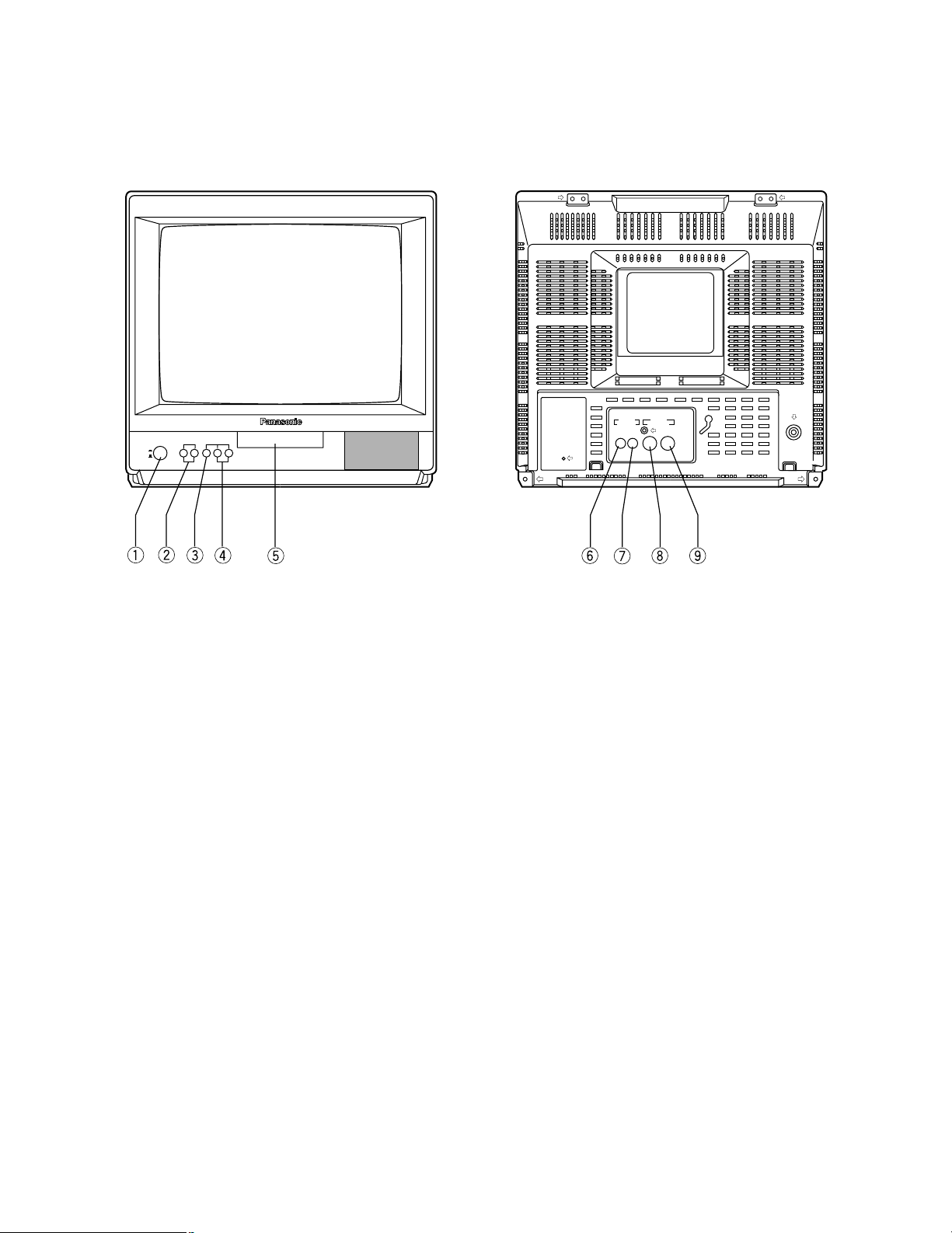
MAJOR OPERATING CONTROLS AND THEIR FUNCTIONS
1. Power Switch (POWER, ON/OFF)
This is a push-push type switch which turns the power
of this monitor on and off.
Press once and the switch remains down (;) for
turning on the power of monitor.
Press again, the switch comes up (l ) for turning off
the power of the monitor.
2. Audio Control Buttons (–AUDIO+)
Press these buttons to increase or decrease the sound
volume level.
3. Menu Button (MENU)
Press to display the setup display or move the cursor
down one line in the setup display.
4. Level Control Button (–LEVEL+)
Press these buttons to adjust level of the selected item
in the setup display, or select a parameter in the setup
display.
5. Power Indicator
This indicator lights up (red) when the Monitor’s power
is turned on.
6. Audio Output Connector (AUDIO OUT)
The audio input signal connected to the audio input
connector u is looped through to this connector.
7. Audio Input Connector (AUDIO IN)
For input of audio signal from an outboard device.
8. Video Output Connector (VIDEO OUT)
The video input signal connected to the video input
connector o is looped through to this connector and
terminated automatically.
9. Video Input Connector (VIDEO IN)
For input of the PAL composite video signal from an
outboard device.
POWER
ON
OFF
–AUDIO+ MENU –LEVEL+
Color Monitor WV-CK1420
AUDIO VIDEO
OUT IN
OUT IN
■ WV-CK1420
Page 4
– 2 –
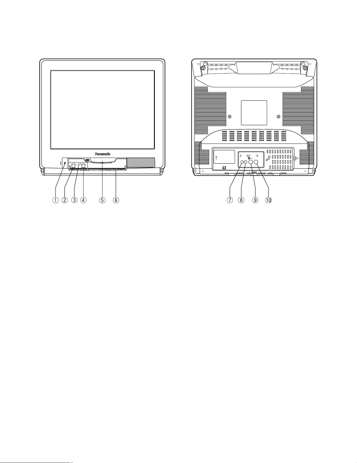
■ WV-CK2020
1. Power Switch (POWER, ON/OFF)
This is a push-push type switch which turns the power
of this monitor on and off.
Press once and the switch remains down (;) for
turning on the power of monitor.
Press again, the switch comes up (l) for turning off the
power of the monitor.
2. Audio Control Buttons (–AUDIO+)
Press these buttons to increase or decrease the sound
volume level.
3. Menu Button (MENU)
Press to display the setup display or move the cursor
down one line in the setup display.
4. Level Control Button (–LEVEL+)
Press these buttons to adjust level of the selected item
in the setup display, or select a parameter in the setup
display.
5. Power Indicator
This indicator lights up (red) when the Monitor’s power
is turned on.
6. Control Panel Cover
Press to open for access to the control buttons on the
Control Panel.
7. Audio Output Connector (AUDIO OUT)
The audio input signal connected to the audio input
connector i is looped through to this connector.
8. Audio Input Connector (AUDIO IN)
For input of audio signal from an outboard device.
9. Video Output Connector (VIDEO OUT)
The video input signal connected to the video input
connector !0 is looped through to this connector and
terminated automatically.
10. Video Input Connector (VIDEO IN)
For input of the PAL composite video signal from an
outboard device.
AUDIO VIDEO
OUT IN
OUT IN
Color Monitor WV-CK 2020
POWER
–AUDIO+ –LEVEL+MENU
ON
OFF
Page 5
– 3 –
1. Test Equipment Required
8
The following equipments are required for adjustment of
WV-CK1420 and WV-CK2020 Colour Video Monitors.
8
Oscilloscope
8
Digital Voltmeter
8
TV Signal Generator
8
Degaussing Coil
8
Tamper Proof Screwdriver
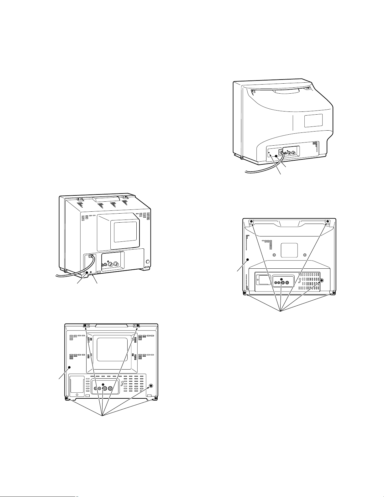
2. Disassembling Procedure for the Adjustment
■ WV-CK1420
8
Referring to Fig. 2-1, remove one screw that secure the
Cord Holder and remove the Cord Holder.
Fig. 2-1
8
Referring to Fig. 2-2, remove six screws that secure the
Rear Cover and remove the Rear Cover.
Fig. 2-2
ADJUSTMENT PROCEDURE
Remove one screw.Cord Holder
■ WV-CK2020
8
Referring to Fig. 2-3, remove one screw that secure the
Cord Holder and remove the Cord Holder.
Fig. 2-3
8
Referring to Fig. 2-4, remove six screws that secure the
Rear Cover and remove the Rear Cover.
Fig. 2-4
Remove six screws.
Rear Cover
Remove one screw.
Cord Holder
Remove six screws.
Rear Cover
Page 6
– 4 –
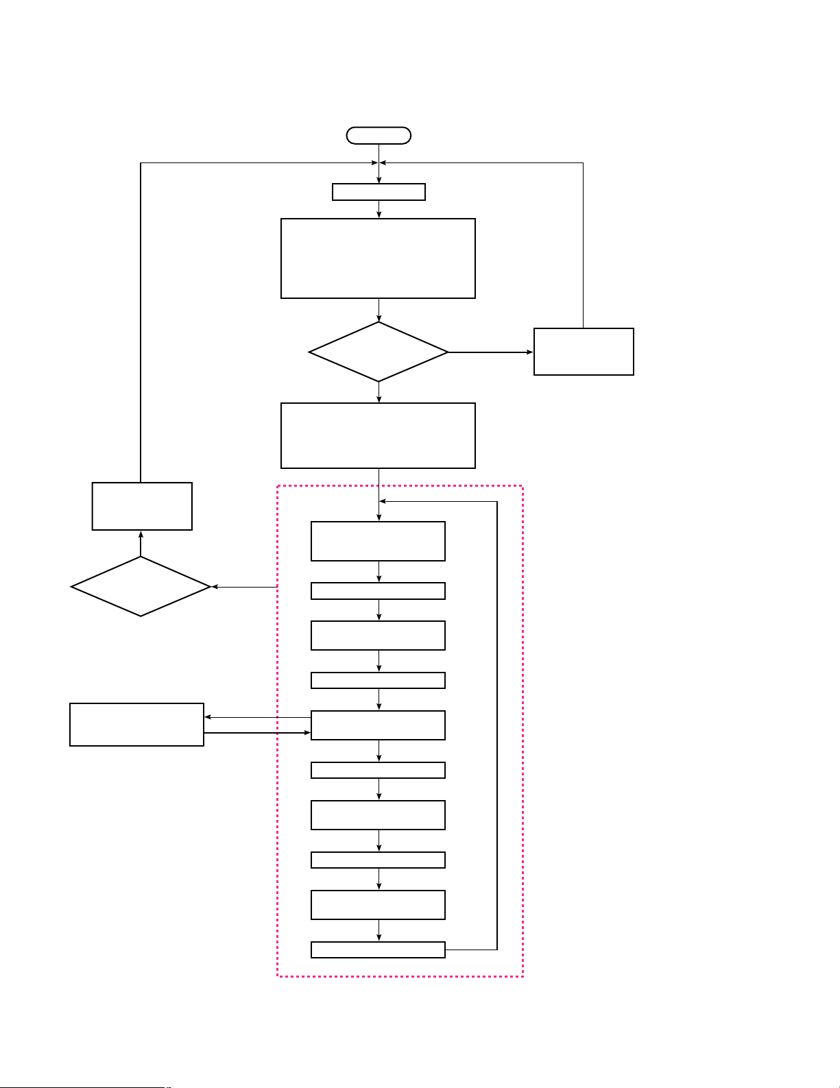
3. Adjustment Flowchart
8
The Fig. 3-1 shows the Adjustment Flowchart.
Fig. 3-1
START
Normal Mode
Service
Yes
Normal
Service Mode (Normal Screen)
Pressing MENU and
Audio Control – Button
simultaneously.
Enter to Service Mode by pressing MENU
and Audio Control + Button simultaneously.
Enter to Factory Mode by pressing MENU
Button and Audio Control + Button
simultaneously again.
Pressing MENU and
Audio Control – Button
simultaneously
Enter to Factory Mode by shorting at once
between FA1 and ground, the Yellow "CHK"
Character will be appeared on the Screen.
Pressing Level Control + Button so that the
Screen changes to the White and changes
to the Transparency after aging.
Normal Mode
or
Service Mode
Return to Normal Mode
?
"CHK" Character has been
changed to the RED.
Pressing MENU Button
CHK 1 (RED)
Adjusting Item
CHK 1 Item : Sub Adjustment
Select : Audio Control + and – Buttons
Press the Audio Control + Button, adjustment mode has
been selected the BRIGHT, SUB BRIGHT, CONTRAST,
SUB CONTRAST, PICTURE, SUB PICTURE, COLOUR
and SUB COLOUR sequentially.
Adjust :Level Control + and – Buttons
Press Level Control + Button in this mode,
the colour of the Screen has been changed to
White, Blue, Green, Red and Transparency
sequentially.
CHK 2 Item : White Balance Adjustment
Select : Audio Control + and – Buttons
Press the Audio Control + Button, adjustment mode
has been selected the R-CUTOFF, G-CUTOFF,
B-CUTOFF, BRIGHT, SUB BRIGHT, R-DRIVE and
B-DRIVE sequentially.
Adjust :Level Control + and – Buttons
CHK 3 Item : Deflection Adjustment
Select : Audio Control + and – Buttons
Press the Audio Control + Button, adjustment mode
has been selected the HC, VH and VC sequentially.
Adjust :Level Control + and – Buttons
CHK 4 Item : Option Adjustment
Select : Audio Control + and – Buttons
Press the Audio Control + Button, adjustment mode
has been selected the AV COLOUR, NOISE MUTE,
TONE, TRAP, DEMO and OSD sequentially.
Adjust :Level Control + and – Buttons
Pressing MENU Button
CHK 2 (RED)
Adjusting Item
H1 LINE MODE
(R-Cutoff, G-Cutoff, B-Cutoff
and Sub Bright Adjustment)
Pressing MENU Button
CHK 3 (RED)
Adjusting Item
Pressing MENU Button
Pressing MENU Button
CHK 4 (RED)
Adjusting Item
Short between
FA3 and ground
(1.424 - 1.696 V)
Voltage
except
above
Service Mode
Page 7
– 5 –
8
Short between FA1 and ground at once to set the
FACTORY Mode, the Yellow "CHK" Character will be
displayed on the Screen, and press the LEVEL
CONTROL (+) Button the Screen changes to the White.
The Screen changes to the Transparency after aging.
8
Return to the Normal Mode from the FACTORY Mode by
pressing the MENU Button and AUDIO CONTROL (–)
Button simultaneously.
8
Enter to the SERVICE Mode from the FACTORY Mode
by pressing the MENU Button and AUDIO CONTROL (+)
Button simultaneously, the "CHK" Character has been
changed to the Red.
8
Return to the FACTORY Mode from the SERVICE Mode
by pressing the MENU Button and AUDIO CONTROL (+)
Button simultaneously.
8
Return to the Normal Mode from the SERVICE Mode by
pressing the MENU Button and AUDIO CONTROL (–)
Button simultaneously.
8
In the SERVICE Mode (Normal Screen), the colour of the
Screen has been changed to White, Blue, Green, Red and
Transparency sequentially every pressing the LEVEL
CONTROL (+) Button.
8
In the SERVICE Mode (Normal Screen), to enter the
CHK1 Mode by pressing the MENU Button and the
Adjustment Items will be displayed on the Screen.
8
The Bright, Sub Bright, Contrast, Sub Contrast, Picture,
Sub Picture, Colour and Sub Colour Adjustments will be
done in this mode.
8
To enter the CHK2 Mode by pressing the MENU Button
and the Adjustment Items will be displayed on the Screen.
8
To enter the H1 LINE Mode by shorting the FA3 and
ground.
8
The R-Cutoff, G-Cutoff, B-Cutoff, Bright, Sub Bright, RDrive and B-Drive Adjustments will be done in this mode.
8
To enter the CHK3 Mode by pressing the MENU Button
and the Adjustment Items will be displayed on the Screen.
8
The HC, VH and VC Adjustments will be done in this
mode.
8
To enter the CHK4 Mode by pressing the MENU Button
and the Adjustment Items will be displayed on the Screen.
8
The AV Colour, Noise Mute, Tone, Trap, Demo, OSD
Adjustments will be done in this mode.
8
Return to the first menu of the SERVICE Mode by
pressing the MENU Button.
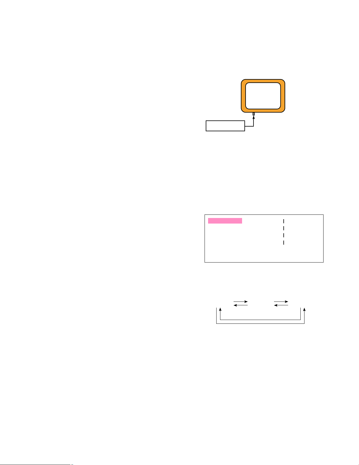
4. Connection And Setting Up
4.1. Connection
8
The Fig. 4-1 shows the connection diagram for the
adjustment procedure.
Fig. 4-1
8
Connect the coaxial cable between Video Input Connector
of the Colour Monitor and Video Output Connector of TV
Signal Generator.
4.2. Setting Up
8
Turn ON the Power Switch.
8
Press the MENU Button, the setup Menu will be displayed
as shown in Fig. 4-2.
Fig. 4-2
8
Select the desired LANGUAGE by pressing the LEVEL
CONTROL (–) or (+) Buttons, pressing the Buttons will
toggle the Setup display in selected as shown in fig. 4-3.
Fig. 4-3
8
Move the cursor to the BRIGHT, CONTRAST, PICTURE,
COLOUR by pressing the MENU Button and set all values
to 32 (Center position) as an initial setting.
BRIGHT
CONTRAST
PICTURE
COLOUR
NORMAL SETTING
LANGUAGE
8888888888888
8888888888888
8888888888888
8888888888888
8888888888888
8888888888888
8888888888888
8888888888888
ENGLISH
ENGLISH FRENCH SPANISH
LEVEL CONTROL (+)
LEVEL CONTROL (–)
TV Signal Generator
Colour Monitor
Page 8
– 6 –
5. Adjustment Procedure
8
Refer to the Location of the Test Points and Adjusting
Controls on page 9.
(1). Sub Contrast Adjustment
Test Point : Pin 3 of A11 (G) Main Board
Adjust : LEVEL CONTROL (+) Main Board
LEVEL CONTROL (–) Main Board
8
Turn OFF the Power Switch.
8
Supply the Colour Bar signal to the Video Input
Connector.
8
Short between Anode of D504 and ground by jumper wire
to stop the ABL.
8
Turn ON the Power Switch.
8
Set the Service Mode and select the "CHK 1" mode.
8
Select the BRIGHT Item.
8
Set the BRIGHT Item to the minimum position (0).
8
Select the CONTRAST Item.
8
Set the CONTRAST Item to the maximum position (63).
8
Connect the Oscilloscope to the pin 3 of Connector A11
on the Main Board.
8
Adjust SUB BRIGHT so that the signal between Black and
White at the pin 3 of A11 does not saturate.
8
Adjust SUB CONTRAST so that the signal between Black
and White at the pin 3 of A11 becomes 3.1 ± 0.1 V.
8
Remove jumper wire from Anode of D504 and ground.
(2). Colour Output Adjustment
Test Point : Q353-C (B) for WV-CK1420
CRT Socket Board
Q354-C (B) for WV-CK2020
CRT Socket Board
Adjust : LEVEL CONTROL (+) Main Board
LEVEL CONTROL (–) Main Board
8
Supply the Colour Bar signal to the Video Input
Connector.
8
Set the Service Mode and select the "CHK 1" mode.
8
Select the BRIGHT Item.
8
Set the BRIGHT Item to the minimum position (0).
8
Select the CONTRAST Item.
8
Set the CONTRAST Item to the center position (32).
8
Select the PICTURE Item.
8
Set the PICTURE Item to the minimum position (0).
8
Select the COLOUR Item.
8
Set the COLOUR Item to the enter position (32).
8
Connect the Oscilloscope to the Collector of Q353 for WVCK1420 or Collector of Q354 for WV-CK2020 on the CRT
Socket Board.
8
Adjust SUB COLOUR so that the Colour Output signal
becomes 29 ± 1 Vp-p for WV-CK1420/B, 36 ± 1 Vp-p for
WV-CK1420/G, 32 ± 1 Vp-p for WV-CK2020/B and 38 ± 1
Vp-p for WV-CK2020/G as shown in Fig. 5-1.
Fig. 5-1
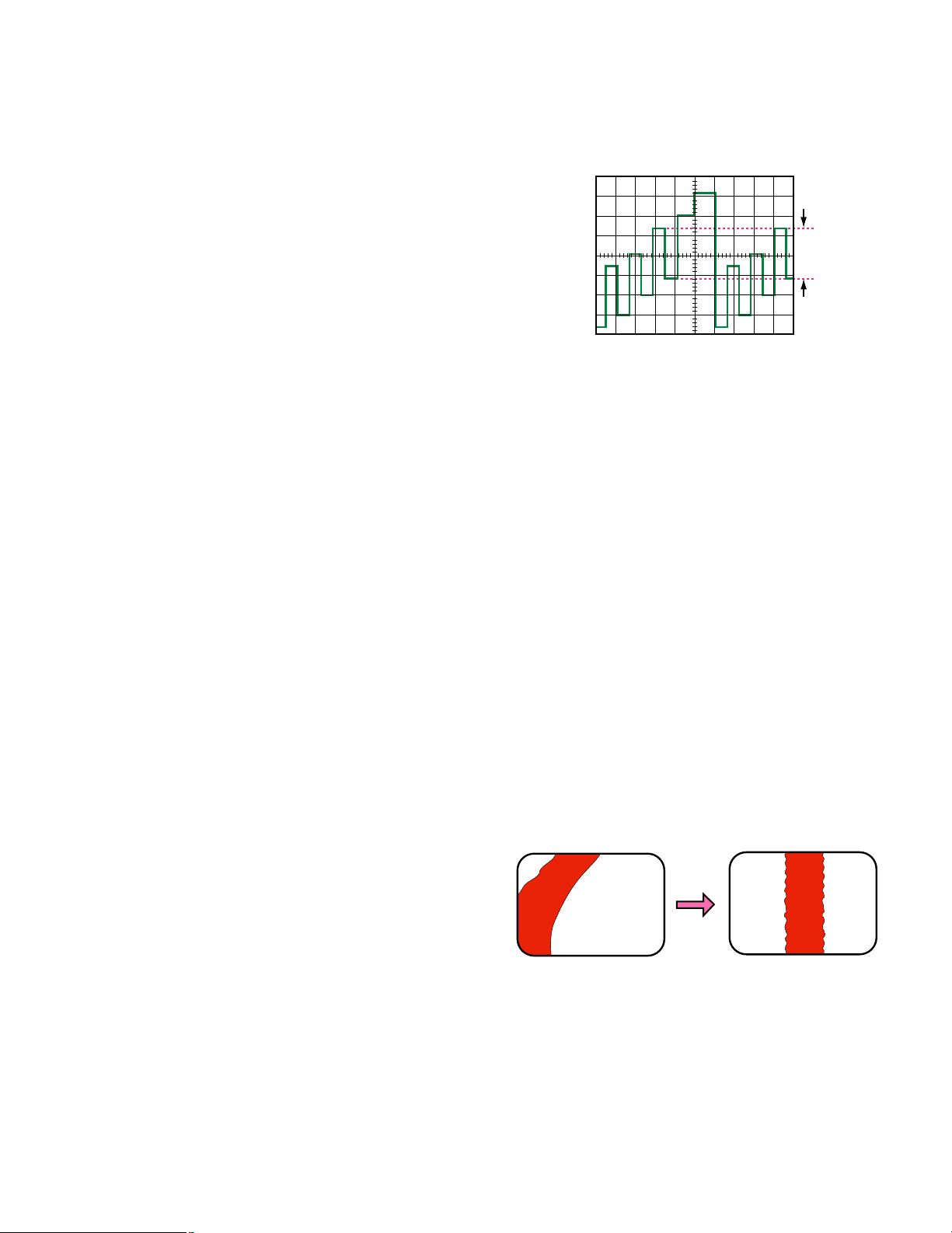
(3). Purity Adjustment
Adjust : Purity Magnet Deflection Coil
Observe : Colour Monitor
8
This adjustment should be done after aging for more than
30 minutes.
8
Degauss the CRT using a Degaussing Coil.
8
Supply the Cross-Hatch signal to the video Input
Connector.
8
Loosen both Deflection Coil Fixing Screw and Magnet
Holding Screw.
8
Adjust the Convergence roughly by the Convergence
Magnet and Deflection Coil.
8
Move Deflection Coil to the rear direction (CRT Socket
Board side).
8
Supply the Red Colour signal to the video Input
Connector.
8
Adjust the Purity Magnet so that the Red area comes to
the center on the CRT Screen as shown in Fig. 5-2.
8
Rotate the deflection coil to find the point where the red
colour whose center portion becomes equal on the CRT
Screen as shown in Fig 5-2.
Fig. 5-2
8
Move the deflection coil forward until red colour fully
occupies the entire screen and tighten the deflection coil
fixing screw.
χ
Vp-p
NO GOOD GOOD
RED RED
Page 9

– 7 –
8
The magnets holding screw will be fastened after
completing next step.
(4). Convergence Adjustment
Adjusts : Convergence Magnet-1
Convergence Magnet-2
Observe : Colour Monitor
8
Supply the Dot signal to the Video Input Connector.
8
Adjust the PICTURE and BRIGHT so that much easy to
see the picture on the Screen.
8
Adjust the Convergence Magnet-1 as shown in Fig. 5-3 so
that red and blue dots on the center area of the CRT
Screen is overlapped.
8
Adjust the Convergence Magnet-2 as shown in Fig. 5-3 so
that the green and magenta (Red + Blue) dots on the
center area of the CRT Screen is overlapped (dots
becomes White).
Fig. 5-3
8
Change the signal from Dot signal to Cross-Hatch signal.
8
If a discrepancy appears at the corner area, slightly adjust
the Convergence Magnets 1 and 2.
8
Repeat above adjustment (Convergence Magnets 1 and
2) until no discrepancy appears on the entire screen.
8
Tighten the Magnets Holding Screw.
(5). White Balance Adjustment
Test Point : Pin 3 of A11 (G) Main Board
KG (Cathode of Green) CRT Socket Board
Adjust : SCREEN Control
Flyback Transformer on the Main Board
LEVEL CONTROL (+) Main Board
LEVEL CONTROL (–) Main Board
Observe : Colour Monitor
8
Supply the Monoscope signal to the Video Input
Connector.
8
Set the Service Mode and select the "CHK 1" mode.
8
Select the BRIGHT Item.
8
Set the BRIGHT Item to the center position (32).
8
Select the CONTRAST Item.
8
Set the CONTRAST Item to the maximum position (63).
8
Select the PICTURE Item.
8
Set the PICTURE Item to the center position (32).
8
Select the COLOUR Item.
8
Set the COLOUR Item to the center position (32).
8
Select the "CHK 2" Mode.
8
Select SUB BRIGHT Item.
8
Set the R-CUTOFF to (0), G-CUTOFF to (125) and BCUTOFF to (0).
8
Set the R-DRIVE to (40) and B-DRIVE to (40).
8
Short between FA3 and ground by jumper wire.
8
Set the SCREEN Control of the Flyback Transformer to
fully counterclockwise direction.
8
Connect the Oscilloscope to the pin 3 of Connector A11
on the Main Board.
8
Adjust the SUB BRIGHT so that the voltage at the pin 3 of
A11 becomes 2.2 ± 0.05 V DC as shown in Fig. 5-4.
Fig. 5-4
8
Remove the jumper wire from FA3 and ground.
8
Set the SCREEN Control to clockwise direction for
illuminating the Screen.
8
Select the G-CUTOFF mode, short between FA3 and
ground by jumper wire.
8
Set the SCREEN Control to fully counterclockwise
direction again.
8
Connect the Oscilloscope to the Cathode of the Green on
the CRT Socket Board.
8
Adjust the SUB BRIGHT so that the voltage at the
Cathode of the Green becomes 140 ± 2 V DC for WVCK1420, 160 ± 2 V DC for WV-CK2020 as shown in Fig.
5-5.
Deflection
Coil
Deflection Coil Fixing Screw
Purity Magnet for WV-CK1420
(Convergence Magnet-1 for WV-CK2020)
Convergence Magnet-1 for WV-CK1420
(Convergence Magnet-2 for WV-CK2020)
Convergence Magnet-2 for WV-CK1420
(Purity Magnet for WV-CK2020)
Magnet Holding Screw
2.2 ± 0.05 V
GND
Adjust center of scanning periode.
Page 10

– 8 –
Fig. 5-5
8
Turn the SCREEN Control slowly, and fix the green
becomes just illuminated point.
8
Adjust the other two low-lights so that the horizontal line
becomes white.
8
Remove the jumper wire from FA3 and ground.
8
Adjust the R-DRIVE and B-DRIVE so that the most
highest portion becomes White.
(6). HC, VC and VH Adjustment
Adjust : LEVEL CONTROL (+) Main Board
LEVEL CONTROL (–) Main Board
Observe : Colour Monitor
8
Set the "CHK 3" Mode.
8
Supply the Monoscope signal to the Video Input
Connector.
8
Select the HC Item.
8
Adjust the HC Data so that the Horizontal Position
becomes center.
8
Select the VC Item.
8
Adjust the VC Data so that the Vertical Position becomes
center.
8
Select the VH Item.
8
Adjust the VH Data so that the full Vertical Height
becomes plus 8 % overscanning.
(7). Sub Bright Adjustment
Adjust : LEVEL CONTROL (+) Main Board
LEVEL CONTROL (–) Main Board
Observe : Colour Monitor
8
Turn ON the Power Switch.
8
Set the "CHK 1" Mode.
8
Select the BRIGHT Item.
8
Set the BRIGHT Item to the center position (32).
8
Select the CONTRAST Item.
8
Set the CONTRAST Item to the center position (32).
8
Select the PICTURE Item.
8
Set the PICTURE Item to the center position (32).
8
Supply the Black Level Pattern signal to the Video Input
Connector.
Adjust center of scanning periode.
140 ± 2 V for WV-CK1420
160
±
2 V for WV-CK2020
GND
8
Adjust SUB BRIGHT Data so that the second portion
becomes slightly lit as shown in Fig. 5-6.
Fig. 5-6
(8). Focus Adjustment
Adjust : FOCUS Control
Flyback Transformer on the Main Board
Observe : Colour Monitor
8
Supply the Dot signal or Cross-Hatch signal to the Video
Input Connector.
8
Adjust the FOCUS Control on the Flyback Transformer to
best focal point.
Adjust the Sub-Bright so that the second
portion becomes slightly lit.
Page 11

– 9 –
A11
FA1 – FA2 : Factory Mode
FA3 – FA2 : H1 Line
TP
A12
D504
180 V
GND
HEATER
TPE3
FA1
SDA
FA3
SCL
FA2
QWERT
QWE
R
S801 (Power Switch)
T501 Flyback Transformer
FOCUS SCREEN
S1106 (Audio Control – Button)
S1105 (Audio Control + Button)
S1103 (Menu Button)
S1104 (Level Control – Button)
S1101 (Level Control + Button)
MAIN BOARD (COMPONENT SIDE)
9 VBGRGND
FRONT SIDE
REAR SIDE
CRT SOCKET BOARD
(COMPONENT SIDE)
EB
C
Q353
Q354
BE
C
LOCATION OF TEST POINTS AND ADJUSTING CONTROLS
Page 12

Video
Input
Connector
Video
Output
Connector
Audio
Input
Connector
AC INPUT
DEGAUSSING COIL
SPEAKER
Audio
Output
Connector
TP5
5V-1
5V-1
9V
AD4 VOLUME
IC1103
RESET
X1160
D1171
D1170
IC1101
MICROPROCESSOR
IC601
PICTURE CONTROL
Q1150
Q1155,D1180,D1181
3
12
AD2
AD3
5
4
6
14
OSC1
40
OSC2
41
EXT-IN
SCL
SDA
B-IN
2830
31
32
G-IN
37
13
17
43
Y-SW OUT
47
AUDIO OUT
57
H-OSC
20
X-TAL (4.43)
41
58
VIDEO-IN
35
CHROMA-IN
33
R-IN
BLUE
GREEN
RED
39
RESET
34
SCL
38
SDA
37
TP3
SCL
VSS
VDD
OUT
IC1102
EEPROM
Q160
8
6
5
4
7
GND
PROTECT
5V
SCL
SDA
+
–
S1105
AUDIO +
D1051
POWER
INDICATOR
S1106
AUDIO –
S1101
LEVEL +
S1104
LEVEL –
S1103
MENU
S1105
D1051
L1 A21
S1106
S1101
S1104
S1103
1
2
3
N.C.
VCC
GND
1
2
3
AFC2 FILTER
32
6
7
TRIGGER2
TPE3
SDA
BUFFER
IC1105
Q404
Q401
R402,R404-407,R451,
R454,R455,C402,C403,
C406,C451,D402
D404
D405
D403
D504
D1145
OUT2
CH2
5
7
3
4
IC401
VERTICAL DRIVER
IN+
PUMPUP
FEEDBACK NETWORK
BIAS CONT.
OUT
IN–
2
5
Q549D870
D580
D401
D870
D392
D393
D394
T550
Q390,D391
CRT
Q353 (WV-CK1420)
Q354 (WV-CK2020)
Q351
Q352
AMP.
Q551
DRIVER
Q548
MUTE P.MUTE
VIDEO CLAMP
51
FM DIRECT
60
SYNC SEP-IN2
49
SYNC SEP-IN1
48
Q161
5V-2
9V-1
D517
D512
BUFFER
IC2301
X520
X625
F802
D802
Q851
IC801,Q801-Q804,
Q850,D821,D840,
D851
F801
S801
POWER SWITCH
T801
POWER
TRANSFORMER
AMP.
Q852,D853,D854
D501
Q580,Q581,D581,
D590,D591
D502
D503
9V REGULATOR
IC850,D871
5V-1 REGULATOR
3
1
3
1
3
1
VOLUME
VOLUME
AUDIO DFT
21
A DEF
POWER
26
V-SYNC
35
AD6
8
BLANK
29
POWER
22V-2
HEATER
5V-1
VOLT AGE
DETECTOR
SWITCHING
REGULATOR
A DEF
N.F.B.
EXT A-IN
59
8
2
4
6
AUDIO BYPASS
POWER BUFFER P.MUTE
9V-1
5V-1
22V-1
90V
ID FILTER
SPOT KILLER
34
8
KILLER FILTER
42
– +
– +
+ –
– +
– +
MUTE FILTER
CHROMA APC FILTER
21
44
APC FILTER
63
VIF IREF
56
+ –
TPY1
+ –
+ –
AFC1 FILTER
+ –
+ –
+ –
+ –
V RAMP
30
19
CONTRAST CTRL
40
V-RAMP
FEEDBACK
FAST BLK
H-OUT
V-OUT
26
29
12
15
B-OUT
24
G-OUT
23
R-OUT
22
SCP-OUT
14
START-UP
27
+ –
– +
– +
LED BOARD MAIN BOARD
CRT SOCKET BOARD
1
2
1
2
1
2
IC851
T501
FL YBACK TRANSFORMER
9V REGULATOR
IC852
5V-2 REGULATOR
9V-2
5V-2
Q1145
HEATER
22V-2
22V-2
X-RAY
PROTECTION
HEATER
BUFFER
BUFFER
BUFFER
HEATER
START UP
START UP
B. CLP
H–
H-SYNC
27
B. CLP
22V-1
5V-1
H–
–
+
90V
9V
1
2
3
4
1
2
3
4
V+
V–
H+
H–
1
2
3
4
5
1
2
3
4
5
9V
B
G
R
GND
1
2
3
4
1
2
3
4
180V(220V)
N.C.
GND
HEATER
3
5
2
6
7
10
4
1
11
9
8
+
–
EHT
FOCUS
SCREEN
SCREEN
FOCUS
SCREEN
FOCUS
EHT
9V
9V-2
22V-1
A12
A11
DY DY1
C12
C11
DEFLECTION COIL
KR
KG
KB
BLOCK DIAGRAM
– 10 –
Page 13

-+
C2309
1000/25
R2313
1K 1/4W
C2313
3300P
R2322
18K
R2310
4.7 1/4W
R2320
1.8K
-+
C2306
22/25
C2311 0.068
-+
C2305
10/16
R2321
82K
-+
C1120
1/50
R1127
56K
R1122
10K
R1121 10K
D1145
JS2303
47K
-+
C2302
10/16
D1180
R1198
10K
Q1155
-+
C1199
22/6.3
R1196
100K
D1181
C1174
0.01
0.01
R1199 1K
1K
R1194
1K
1K
R1197
10K
+5V
R2312 2.2K 1/4W
R2311
10 2W
L1104
10
R1109 100 1/4W
R1110 22K
R1120
10K
S1103 S1105 S1106 S1101 S1104
R1115
10K
R1118
3.3K
R1117
2.2K
R1116
2.2K
C1102
0.01
R1101 10K
(JS1103)
C1101
470P
R1195
10K
12345
C1171
100P
C1170
100P
R1170 56
R1171 56
C1172
0.01
-+
C1173
10/16
R1174
47 1/4W
D1170
R1172 3.3K
R1173 3.3K
D1171
+5V
X1160
L1152
-+
C1160
470/
16
D1160
C1161
0.01
+5V
R1158
100
R1157
100
L1151
10
L1135
10
R1152 5.6K
R1151 5.6K
R1150 1.8K
R1153 5.6K
R1156
1K 1/4W
C1153
82P
C1152
82P
C1151
82P
C1149
56P
+5V
R1143
100 1/4W
R1146
10K
L1140
10
R1145
2.2K
Q1145
D1120
C1145
∗
C1138 0.01
-+
C1137
22/16
C1135
0.01
(JS651)
(JS650)
(JS652)
(JS653)
R651
910
R650
910
R652
910
R653
5.6K
R1163 1.2K
Q1150
R1164 6.8K
C1157 0.01
C1156
1000P
R1162
124K
R1161
22K
R1160
68K
R1053
680
D1051
(TPE13)
R168 0
-+
C168 0.33/50
R166
390
C169
220P
C204
2200P
C211
1/50
-+
C202
3.3/50
R211
82K
R212
10K
R203
390
R201
470
-+
C203
10/16
C165
100P
C201 0.068/16V
R202
1K
+9V
C634 0.01-+C633 330/10
R164
270
Q161
C526
0.01
R431 270K
C430 0.01
R430 220
-+
C431 1/50
-+
C531
1/50
R530 100
C530 1200P
R170 470
R163 3.3K
Q160
JA20 0
R160
220
R627
4.7K
-+
C627
0.47/50
C628 0.015
R628
9.1M
C626 0.01
R625 1.5M
R526 470
-+
C525 3.3/50
C613 0.1 C612 0.1
R161 330K
-+
C160 10/50
C585 0.1
R620
220
C622
0.22/
16V
C621 0.022
C161 0.1
R162 33
L150 100
+5V
C156
0.01
-+
C155
47/16
-+
C601
0.22/50
R605
10
1/4W
C604 68P
C519 33P
R606
10
1/4W
C521
3300P
C540
560P
X520
R523
27K
-+
C520
1/50
R521 9.1M
-+
C606 47/16
C605 0.01
C420 0.1/25V
R420 150K
C611
0.1
R425
22K
1/4W
R421
270
D517
-+
∗
C610
-+
C425 1/25
C522 8200P
R525 220K
R524
680K
-+
C615 100/6.3
C616
0.022
(JS610)
+5V
L611
+9V
R654
2.7K
1/4W
R3007
75
KRKGKB
H
E
G1G2G3
1
F802
3.15A
250V
1
2
3
4
5
C354
820P
2KV
1
2
3
4
C356
0.01 500V
C357
∗
C350
330P
1
2
3
4
5
1
2
3
4
L640 10
R643 330
(TPE28)
D394
Q390
D391
-+
C390
330/16
(TPE27)
D393 D392
L641 10
R644 330
L642 10
R645 330
R390 1K
+9V
C642
33P
R640
∗
C641
33P
C640
33P
R641
∗
R642
∗
R520
5.6K
R516
2.2K
R515
39K
R513
1.5K
D512
L612 0.47
D405
Q404
R414
33K
R413
2.2K 1/4W
D404
Q401
R412
4.7K
R411
5.6K
D403
+ -
C410
0.22/50
R410 10K
R514
D504
+ -
C501
0.1/50
C405
1000P
D401
+ -
C452
100/35
R451
∗
C451
0.22 100V
R454
∗
R453
1K
R455
220
C453
∗
R405
∗
R404
∗
R407
∗
-+
C403
2200/35
-+
C402
∗
D402
R402
1.8K
C406
1000P
R406
∗
-+
C401
1000/35
L402
C552
∗
D551
L552
R552
1K 1W
Q551
C558
∗
D552
C553
0.022
400V
C555
0.027
400V
L551
C551
∗
C559
∗
L553
L554
C560
∗
R551
∗
JS502
R501
1 1/2W
D501
C503
470P 500V
R503
∗
R504
22K
-+
C506
∗
R510
56K
D510
R511
100K
-+
C510
47/10
+5V
C504
470P
500V
D502
-+
C507
470/25
R585
330K
R586
68K
D581
Q581
+9V
R584
10K
-+
C581
10/63
R587
100K
R588
10K
R589
22K
R502
1 1/2W
D503
C505
560P 500V
-+
C508
3300/35
Q580
-+
C580
33/
10
R581
10K
R582
1.5
2W
D580
R580
82K
1/4W
-+
C582
1/50
R592
10
D591
D590
R591
14.7K
-+
C590
100/35
L580
C591 330P
500V
R590
19.6K
L557
R547
∗
-+
C546
1/50
Q549
R550
∗
C548
∗
R548
∗
R549
∗
+9V
-+
C830
100/6.3
(TPE10)
R862 6.2 2WR861 3.3 2W
R863
3.3 2W
1
IN3OUT
GND
2
IC851
+9V
-+
C833
100/16
-+
C828
330/25
L850
Q852
R853
220 2W
R854
2.2K 2W
D853
D854
-+
C854
10/16
-+
C853
∗
C852
∗
1
IN3OUT
GND
2
IC850
+5V
L870
D871
-+
C871
100/6.3
C851
470P 500V
D870
-+
C870
100/35
R851
240 1/4W
R850
1.5K 1/2W
-+
C850
1000/25
D850
R852
2.2K 2W
R855
1K
1/4W
Q851
R856
1K 1/4W
C858
0.047
R857
2K
1/4W
Q850
D840
D852
R860
1
1/6W
(JS811)
D851
R820
2.7K
7W
R821
∗
R822
3.3K 1W
D821
-+
C823
∗
D820
-+
C831
33/160
(JS820)
R812
750 1/4W
C824
820P
C825
1000P
D816
R817
2.2K 1/2W
D815
Q804
R816
1K 2W
C821
∗
R806
390 3W
C816
∗
D806
C822
∗
D817
L810
C815
∗
(JS806)
D803
(JS805)
Q801
R803
150K 1/2W
R804
150K 1/2W
C820 0.022
R815 47 2W
Q803
Q802
R802 15 2W
C814
∗
C817 0.047
D804 D805
R810
∗
∗
R811
C840
2200P 2KV
R841 8.2M 1/2W
R801
2.2
7W
-+
∗
C810
–+
~
~
D802
C808
4700P
500V
C806
4700P
500V
C809
4700P
500V
C807
4700P
500V
∗
C803
C802
0.1 200V
R807
3.3M 1/2W
L801
D801
C805
0.01 500V
F801
3.15A
250V
C801
0.22
200V
R805
39K 1/4W
∗
R354
Q351
∗
R386
R351
12K 2W
∗
R369
∗
R366
∗
C351
R374
100 1/4W
∗
R367
∗
C352
∗
R370
Q352
R373
100 1/4W
R352
12K 2W
∗
R355
∗
R387
∗
R368
∗
C353
∗
R376
∗
Q353
R372
100 1/4W
∗
R353
∗
R375
∗
R356
(TPY1)
∗
R371
∗
Q354
THERMAL
PROTECTOR
AMP
PUMP
UP
VCCGND
1 2 3 4 5 6 7
IC401
R2314
5.6K 1/4W
-+
C2314
2.2/50
-+
C2307
1000/25
1
2
1
2
3
1
2
3
(TPE3)
C1146
100P
+5V
1
2
1
2
-+
C818
100/10
1
2
3
4
+9V
9 8 7 6 5 4 3 2 1
VCC2
AUDIO
OUTPUT
DC VOL
ATT
MUTE
VCC1
IC2301
C2310
0.068
1
IN3OUT
OUT1
CR1
TRIGGER1
GND
1
2
3
4
8
7
6
5
VCC
OUT2
CR2
TRIGGER2
GND
2
IC852
IC1105
2 1
3
IC801
2
VDD1OUT
VSS
3
IC1103
1
2
3
4
5
6
7
8
9
10
11
12
13
14
15
16
17
18
19
20
21
FA1
NC
NC
NC
NC
TONE
VOLUME
NC
CM
NC
NC
NC
AD6
NC
AD4
AD3
AD2
NC
NC
NC
VIDEO DFTNCNC
NC
POWER
H-SYNC
50/60Hz
BLANK
BLUE
GREEN
RED
NC
RESET
V-SYNC
NC
SDA
SCL
VDD
OSC1
22
23
24
25
26
27
28
29
30
31
32
33
34
35
36
37
38
39
40
41
42
OSC2
GND
AUDIO DFT
IC1101
123
45
678
GND
GND
GND
GND
SDA
SCL
PROTECT
5V
IC1102
1
AFT OUT
QIF OUT
GND
VIF-IN1
VIF-IN2
VCC
FAST BLK
SCL
SPC-OUT
H-OUT
GND
SDA
H-OSC
2
3
4
5
6
7
8
9
10
11
12
13
14
15
16
17
18
19
20
21
22
23
24
25
26
27
28
29
30
31
32 33
34
35
36
37
38
39
40
41
42
43
44
45
46
47
48
49
50
51
52
53
54
55
56
57
58
59
60
61
62
63
64
SIF LMT IN
RF AGC OUT
IF AGC FILT
SPOT KILLER
V-RAMP FEEDBACK
MUTE FILT
R-OUT
G-OUT
B-OUT
GND
V-OUT
START-UP
B-IN
V-RAMP
VCC
AFC2 FILT
VIF GND
VDD DECOUPLING
AFC1 FILT
VIDEO OUT
APC FILTER
VIF2
FM DIRECT OUT
EXT A-IN
AUDIO OUT
VIF IREF
R-Y IN
B-Y IN
HI-VCC
SECAM REF
Y-SW OUT
GND
TV-IN
EXT-IN
R-IN
BLK HOLD
G-IN
X-RAY IN
VIDEO-IN
ID FILTER
CHROMA-IN
CONTRAST CTRL
KILLER FILT
CHROMA APC FILT
SYNC SEP-IN1
SYNC SEP-IN2
VIDEO CLAMP
AUDIO BYPASS
VIF1
X-TAL (4.43)
X-TAL (3.58)
IC601
JA21
0
R1193
0
JA31
0
JA16
0
JA6 0
JA17 0
JA15 0
JA30 0
L555
J212
∗
J264
J307
L501
L558
L620
R167
180
C3209 0
(R3209)
R621
470 1/4W
R623
470
C620
0.022
C630
150P
X626
C645
∗
C646
∗
∗
C647
ANODE
SP+
SP-
(SP)
+
-
SP1
SPEAKER
AUDIO OUT
MENU VOL+ VOL– LEVEL+ LEVEL–
FA1
SDATPFA3
SCL
FA2
EEPROM
RESET
NC
VCC
GND
POWER
INDICATOR
IN
OUT
AUDIO
(EM3100)
IN
OUT
VIDEO
GND
(C10)
AC IN
(AC)
+9V
B
G
R
GND
+170V/+180V
NC
GND
HEATER
FOCUS
SCREEN
+9V
B
G
R
GND
+170V/+180V
HEATER
NC
GND
CN12(A12)
CRT SOCKET BOARD
40M
20M
45M
13M
2M
VF
VS
EHT
11
1
8
2
3
5
6
7
4
10
9
FOCUS
CONTROL
[FOCUS]
SCREEN
CONTROL
T501
FL YBACK TRANSFORMER
ANODE
FOCUS
SCREEN
V+
H-
VH+
(DY)
VERTICAL
HORIZONTAL
L1
DEFLECTION COIL
VERTICAL OUT
MAIN BOARD
T550
+5V REGULATOR
+9V REGULATOR
+5V REGULATOR
NC
NC
P2
B3
P1
B1
NC
S3
NC
S2
NC
S1
NC
NC
T801
POWER TRANSFORMER
S801
POWER
SWITCH
L
N
(DEG)
DC1
DEGAUSSING
COIL
E101
AC POWER CORD
A
B
C
D
1234567
∗
+170V : WV-CK1420
+180V : WV-CK2020
CRT1
CATHODE
RA Y TUBE
NC
VCC
GND
S1103
MENU
SWITCH
S1105
AUDIO
CONTROL
+BUTTON
S1101
LEVEL
CONTROL
+BUTTON
∗
LED BOARD
L
N
MODEL
WV-CK1420
WV-CK2020
2.2K
2.4K
R404 R405 R406 R407
560
120
2.2 1W
1.5 1W
620
330
2.2 1W
4.7 1W
R451
750 1/4W
R454
1K 1/4W
180K
1/4W
R503
178K
1/4W
1.2 2W
R514
2.7 2W 100 2W
R547
36 2W
1K
R548
820
2.2K
1.2K
R549
470 2W
330 2W
R550
OPEN
R551
100
1/2W
820
R640
1.5K
820
1.5K
820
1.5K
R641 R642
12K
1/4W
R810
10K
1/4W2K1/2W
R811
1.8K
1/2W
15K
2W
R821
8.2K
3W
10/35
C402
33/35
0.033
50V
C453
6800P
50V
10/250
22/250
C506
0.012
C548
0.047
220P
2KV
C551
470P
2KV
C552
0.012
1.2KV
0.015
1.2KV
C558
1500P
2KV
4700P
1.2KV
0.82
500V
0.56
500V
C559
OPEN
C560
0.47
500V
470/10
C610
1000/10
470P
2KV
C803
220P
2KV
C810
330/200
270/200
1500P
2KV
1000P
2KV
C814 C815
0.15
0.22 0.033
0.01
C816
2200P
2KV
C822
820P
2KV
C823
680/160
1000/160
470P 2KV
2200P
500V
C852
220/50
C853
470/50
OPEN
J264
MOUNT
MODEL
WV-CK1420
WV-CK2020
Q353 Q354 R353 R354 R355
390 1/4W
R356
330 1/4W
R366 R367 R368
5.6K
1/4W
3.3K
1/4W
R369 R370
OPEN
R371
0.022
200V
R375
470P 560P
R376 R386 R387 C351 C352 C353 C357
OPEN390P
560P
2.7K
1/2W
OPENOPENOPEN
2.7K
1/2W
2.7K
1/2W
12K
2W
5.6K
1/4W
3.3K
1/4W
5.6K
1/4W
3.3K
1/4W
390 1/4W
330 1/4W
390 1/4W
330 1/4W
2.7K 1W
2.7K 1W2.7K 1W
OPEN OPEN OPEN
OPEN
OPEN
MOUNT
MOUNT OPEN
12K 2W
∗
marked parts of the CRT Socket Board are shown in below.
∗
marked parts of the Main Board are shown in below.
330P 390P
S1106
AUDIO
CONTROL
–BUTTON
S1104
LEVEL
CONTROL
–BUTTON
CN14
(A21)
CN1
(L1)
CN1(JK14)
CRT SOCKET
CN1(JK14)
E12
(C12)
CN11
(A11)
C1145
680P
68P
C821
0.027
0.022
L554
OPEN
MOUNT
E11
(C11)
C647
82P
C646
68P
C645
68P
82P
68P
82P
SCHEMATIC DIAGRAM
IC401 A5
IC601 C4
IC801 A2
IC850 A3
IC851 B3
IC852 B3
IC1101 C2
IC1102 D3
IC1103 C2
IC1105 C2
IC2301 D1
Q160 D5
Q161 D4
Q390 B5
Q401 B4
Q404 B4
Q549 A3
Q551 A4
Q580 A4
Q581 B3
Q801 B1
Q802 A1
Q803 A1
Q804 A1
Q850 A3
Q851 A3
Q852 B3
Q1145 B1
Q1150 C3
Q1155 D2
D391 B5
D392 B6
D393 B6
D394 B6
D401 A5
D402 A6
D403 B4
D404 B4
D405 B4
D501 B4
D502 B4
D503 B4
D504 A5
D510 B4
D512 B5
D517 C5
D551 A4
D552 A4
D580 A3
D581 B3
D590 B3
D591 B3
D801 B2
D802 B2
D803 A1
D804 A1
D805 A1
D806 B2
D815 A2
D816 A2
D817 B2
D820 A2
D821 A2
D840 A2
D850 A3
D851 A3
D852 A3
D853 B3
D854 A3
D870 A3
D871 A3
D1120 D1
D1145 B2
D1160 C3
D1170 C3
D1171 C3
D1180 D2
D1181 D2
< INDEX >
MAIN BOARD
< INDEX >
CRT SOCKET BOARD
< INDEX >
LED BOARD
Q351 B7
Q352 B7
Q353 B7
Q354 A7
D1051 B1
Important safety notice
Components Identified by " " mark have special characteristics for safety.
When replacing any of these components, use only manufacturer's specified parts.
– 11 –
Page 14

TO
DEGAUSSING
COIL
MAIN BOARD
MAIN BOARD
LED BOARD
CRT SOCKET BOARD
(COMPONENT SIDE)
(COMPONENT SIDE)
(COMPONENT SIDE) (PATTERN SIDE)
(PATTERN SIDE)
FOCUS,SCREEN:TO CRT SOCKET BOARD
ANODE:TO CRT
TO
DEFLECTION
COIL
TO
AC POWER
CORD
A
B
C
D
E
F
1
23
4 5 6 78
< INDEX >
MAIN BOARD
< INDEX >
CRT SOCKET BOARD
IC401 C2
IC601 D2
IC801 C2
IC850 C4
IC851 C2
IC852 D2
IC1101 D4
IC1102 D4
IC1103 C3
IC1105 C3
IC2301 E3
Q160 D7
Q161 D7
Q390 E2
Q401 E7
Q404 E8
Q549 C2
Q551 A2
Q580 B8
Q581 C8
Q801 B3
Q802 B3
Q803 B3
Q804 B3
Q850 C4
Q851 C4
Q852 C3
Q1145 D6
Q1150 C7
Q1155 C5
D391 E2
D392 E2
D393 E2
D394 E2
D401 C2
D402 C1
D403 E2
D404 E2
D405 E1
D501 B1
D502 B1
D503 B1
D504 C1
D510 C1
D512 C2
D517 E1
D551 B2
D552 B2
D580 C3
D581 C1
D590 C1
D591 C1
D801 A3
D802 A3
D803 B3
D804 B3
D805 C3
D806 B3
D815 B3
D816 C3
D817 C3
D820 A2
D821 C3
D840 C4
D850 C3
D851 C4
D852 C3
D815 B3
D816 C3
D817 C3
D820 A2
D821 C3
D840 C4
D850 C3
D851 C4
D852 C3
D853 C3
D854 C3
D870 C3
D871 C4
D1120 E3
D1145 D3
D1160 D4
D1170 D4
D1171 D4
D1180 C4
D1181 C4
Q351 E4
Q352 E4
Q353 F4
Q354 F4
< INDEX >
LED BOARD
D1051 D4
CONDUCTOR VIEW
– 12 –
Page 15

1
5
5
5
5
6
6
4
4
2
3
3
XTB4+15FN
XTW3+12JFX
XTB4+20FX
XTB4+15FX
XYN3+10FX
XTW3+8JFX
Pan Head Screw and Washer Assy
Pan Head Screw and Washer Assy
Binding Head Tapping Screws
Binding Head Tapping Screws
Pan Head Screw and Washer Assy
Wahser Head Tapping Screws
1
2
3
4
5
6
ScrewsNo. Description
Numbers show screws, washers, nuts and etc.
M1
M4
M5
M32
M6
M7
M8
M34
M9
M11
M12
M16
Serial No. Label
M14
M15
E101
M13
PCB2
M17
M17
M17
CRT1
M21
PCB3
M23
M24
E102
M25
M29
M51,M52
M53
M54
M54
M57
M54
M54
M55
M56
M26
M28
M22
L1
L2
PCB1
M3
M2
M10
SP1
PACKAGING
DC1
WV-CK1420
SP2
M19
M35
M36
– 13 –
EXPLODED VIEW OF WV-CK1420
Page 16

5
5
5
5
1
6
6
4
4
2
3
XTB4+12FX
XTW3+12JFX
XTB4+20FX
XTB4+15FX
XYN3+10FX
XTW3+8JFX
Binding Head Tapping Screws
Pan Head Screw and Washer Assy
Binding Head Tapping Screws
Binding Head Tapping Screws
Pan Head Screw and Washer Assy
Wahser Head Tapping Screws
1
2
3
4
5
6
ScrewsNo. Description
Numbers show screws, washers, nuts and etc.
M1
M2
M3
M6
M7
M32
M8
M9
M10
M28
M28
M15
M14
M18
Serial No. Label
M16
M17
E101
M12
M12
M13
DC1
PCB2
M11
CRT1
M25
M19
M21
PCB3
M23
M24
M35
M36
M26
M29
M51,M52
M53
M54
M54
M54
M54
M27
M20
M30
M22
E102
L1
L2
PCB1
M4
M5
SP1
SP2
PACKAGING
3
WV-CK2020
M57
M55
M56
EXPLODED VIEW OF WV-CK2020
– 14 –
Page 17

– 15 –
CRT1 Y A34AGT13X31K 14" Cathode Ray Tube
DC1 Y TLK4C9006T Degaussing Coil
L1 CK1420-DY Deflection Coil
L2 CK1420-CY Purity Magnet Assy
SP1 EAS65P309T Speaker
SP2 CK14201AWPB Wire Assy for Speaker
E101 Y TSX4C1A013B AC Power Cord Assy for WV-CK1420/B
TSX4C1A013G AC Power Cord Assy for WV-CK1420/G
E102 FBTFS2831-2 Wire Assy
M1 TKK4C1A032A Smoke Cover
M2 TBX4C1A060 Hinge Button
M3 TBX4C1A061 Power Button
M4 TBM4C1A02701 Panasonic Badge
M5 Y TKY4C1A002E Front Cabinet Assy
M6 XWG5E20FCX CRT Washer
M7 TMM4C1A007 CRT GUM
M8 THT4C1A535 Screw for CRT
M9 Y TMM15404-1 H.V Wire Clamper
M10 TKK4C1A037-B LED Spacer
M11 CK142020WPA 14" C.R.T. Wire
M12 XF5B10K40171 Rope
M13 TES201 Spring
M14 Y TKK4C1A07101 Cord Clamp
M15 Y TQF4C1A06801 Main Label for WV-CK1420/B
TQF4C1A06802 Main Label for WV-CK1420/G
M16 Y TKU4C1A002D Rear Cover
M17 TMM6024-1 DY GUM
M19 THT4C1A415 Screw for Speaker
M26 TMM4C1A053 PCB Support
M29 TMM6428-1 Clamper
M32 Y TQF4C1A075 X-Ray Label for WV-CK1420/G
M34 Y TQF4C1A07401 CRT Caution Label for WV-CK1420/B
TQF4C1A07402 CRT Caution Label for WV-CK1420/G
M35 TMM5402-1 Wire Clamper A
M36 TMM81416 Wire Clamper B
PCB1 (RTL) CK1420/B-CMA Printed Circuit Board Assy
for WV-CK1420/B
PCB1 (RTL) CK1420/G-CMA Printed Circuit Board Assy
for WV-CK1420/G
IC401 LA7840 IC
IC601 M52770ASP IC
IC801 SE090NLF4 IC
IC850 AN78M05 IC
IC851 AN78M09 IC
IC852 AN78M05 IC
IC1101 MN1871681TG IC
IC1102 S24C02ADP-P IC
IC1103 S-80741AL-Z IC
IC1105 BA225 IC
IC2301 YWAN5265 IC
Q160,161 2SB709A-RS Transistor
Q390 2SA564A-R Transistor
Q401 2SD601A-QR Transistor
Q404 2SD601A-QR Transistor
Q549 2SD1275A-P Transistor
Q551 2SD2499LBMA Transistor
Q580,581 2SB709A-RS Transistor
Q801 2SC5241 Transistor
Q802,803 2SD789ETZ Transistor
Q804 2SC945AQ Transistor
Q850,851 2SC945AQ Transistor
Q852 2SD1275A-P Transistor
Q1145 2SD601A-QR Transistor
Q1150 2SD601A-QR Transistor
Q1155 2SD601A-QR Transistor
D391-394 MA165 Diode
D401 ERA15-01V5 Diode
D402 MA4360-M Diode
D403 MA4047-H Diode
D404,405 MA165 Diode
D501-503 AU02V0 Diode
D504 MA4330-M Diode
D510 AU02V0 Diode
D512 MA4056L Diode
D517 MA4110-H Diode
D551 ERB06-15V1 Diode
D552 TVSRU2AMV1 Diode
D580 YWD1NL20U Diode
D581 MA4360-L Diode
D590 MA4108J Diode
D591 MA171 Diode
D801 Y DGC3R05M Posistor
REF. NO. PART NO. DESCRIPTION REF. NO. PART NO. DESCRIPTION
REPLACEMENT PARTS LIST
Important Notice
1. Components identified by " Y " mark have special characteristics important for safety.
When replacing any of these components, use only manufacturer's specified parts.
2. RTL : Retention Time Limited (No longer available after discontinuing product).
MISCELLANEOUS
COLOUR MONITOR WV-CK1420
MAIN BOARD
Page 18

– 16 –
D802 Y D4SB80 Diode
D803 MA4120-M Diode
D804 YWD1NL20U Diode
D805 MA4150M Diode
D806 MA4051-H Diode
D815,816 YWD1NL20U Diode
D817 YWS2L60 Diode
D820 TVSSR2KSV1 Diode
D821 0N3131R Photocoupler
D840 Y YWPC123FY2 Photocoupler
D850 YWD1NL20U Diode
D851 MA4024-H Diode
D852 EU02V0 Diode
D853 MA4082M Diode
D854 MA27TA Diode
D870 YWD1NL20U Diode
D871 MA4056-H Diode
D1120 MA165 Diode
D1145 MA165 Diode
D1160 MA4056L Diode
D1170 MA4068M Diode
D1171 MA4068M Diode
D1180 MA4150M Diode
D1181 MA4180-M Diode
R160 ERJ6GEYJ221 Carbon 220 ohms 1/10W
R161 ERJ6GEYJ334 Carbon 330K ohms 1/10W
R162 ERJ6GEYJ330 Carbon 33 ohms 1/10W
R163 ERJ6GEYJ332 Carbon 3.3K ohms 1/10W
R164 ERDS2TJ271 Carbon 270 ohms 1/4W
R166 ERDS2TJ391 Carbon 390 ohms 1/4W
R167 ERJ6GEYJ181 Carbon 180 ohms 1/10W
R168 ERJ6GEY0R00 Carbon 0 ohm 1/10W
R170 ERJ6GEYJ471 Carbon 470 ohms 1/10W
R201 ERJ6GEYJ471 Carbon 470 ohms 1/10W
R202 ERJ6GEYJ102 Carbon 1K ohms 1/10W
R203 ERDS2TJ391 Carbon 390 ohms 1/4W
R211 ERJ6GEYJ823 Carbon 82K ohms 1/10W
R212 ERJ6GEYJ103 Carbon 10K ohms 1/10W
R390 ERDS2TJ102 Carbon 1K ohms 1/4W
R402 ERJ6GEYJ182 Carbon 1.8K ohms 1/10W
R404 ERJ6GEYJ222 Carbon 2.2K ohms 1/10W
R405 ERJ6GEYJ621 Carbon 620 ohms 1/10W
R406 ERDS1FJ2R2 Carbon 2.2 ohms 1W
R407 ERJ6GEYJ561 Carbon 560 ohms 1/10W
R410 ERJ6GEYJ103 Carbon 10K ohms 1/10W
R411 ERJ6GEYJ562 Carbon 5.6K ohms 1/10W
R412 ERJ6GEYJ472 Carbon 4.7K ohms 1/10W
R413 ERDS2TJ222 Carbon 2.2K ohms 1/4W
R414 ERJ6GEYJ333 Carbon 33K ohms 1/10W
R420 ERJ6GEYJ154 Carbon 150K ohms 1/10W
R421 ERJ6GEYJ271 Carbon 270 ohms 1/10W
R425 ERDS2TJ223 Carbon 22K ohms 1/4W
R451 ERDS1FJ2R2 Carbon 2.2 ohms 1W
R453 ERJ6GEYJ102 Carbon 1K ohms 1/10W
R454 ERDS2TJ751 Carbon 3.3K ohms 1/4W
R455 ERJ6GEYJ221 Carbon 220 ohms 1/10W
R501 ERQ12HJ1R0 Fuse Resistor 1 ohm 1/12W
R502 ERQ12ZJ1R0 Fuse Resistor 1 ohm 1/12W
R503 ER025TKF1803 Metal 180K ohms 1/4W
R504 ERJ6GEYJ223 Carbon 22K ohms 1/10W
R510 ERJ6GEYJ563 Carbon 56K ohms 1/10W
R511 ERJ6GEYJ104 Carbon 100K ohms 1/10W
R513 ERJ6GEYJ152 Carbon 1.5K ohms 1/10W
R514 ERQ2CJP2R7S Fuse Resistor 2.7 ohms 20W
R515 ERJ6GEYJ393 Carbon 39K ohms 1/10W
R516 ERJ6GEYJ222 Carbon 2.2K ohms 1/10W
R519 ERJ6GEYJ222 Carbon 2.2K ohms 1/10W
R520 ERJ6GEYJ562 Carbon 5.6K ohms 1/10W
R521 ERJ6GEYJ915V Carbon 9.1M ohms 1/10W
R523 ERJ6GEYJ273 Carbon 27K ohms 1/10W
R524 ERJ6GEYJ684 Carbon 680K ohms 1/10W
R525 ERJ6GEYJ224 Carbon 220K ohms 1/10W
R526 ERJ6GEYJ471 Carbon 470 ohms 1/10W
R530 ERJ6GEYJ101 Carbon 100 ohms 1/10W
R547 ERG2ANJ101 Metal 100 ohms 2W
R549 ERJ6GEYJ222 Carbon 2.2K ohms 1/10W
R548 ERJ6GEYJ102 Carbon 1K ohms 1/10W
R550 ERG2ANJ471 Metal 470 ohms 2W
R552 ERQ1CJP102S Fuse Resistor 1K ohms 1W
R580 ERDS2TJ823 Carbon 82K ohms 1/4W
R581 ERJ6GEYJ103 Carbon 10K ohms 1/10W
R582 ERD2FAVJ1R5 Carbon 1.5 ohms 2W
R585 ERJ6GEYJ334 Carbon 330K ohms 1/10W
R584 ERJ6GEYJ103 Carbon 10K ohms 1/10W
R586 ERJ6GEYJ683 Carbon 68K ohms 1/10W
R587 ERJ6GEYJ104 Carbon 100K ohms 1/10W
R588 ERJ6GEYJ103 Carbon 10K ohms 1/10W
R589 ERJ6GEYJ223 Carbon 22K ohms 1/10W
R590 ERJ6ENF1962V Carbon 19.6K ohms 1/10W
R591 ERJ6ENF1472 Carbon 14.7K ohms 1/10W
R592 ERJ6GEYJ100 Carbon 10 ohms 1/10W
R605 ERD25FJ100 Carbon 10 ohms 1/4W
R606 ERD25FJ100 Carbon 10 ohms 1/4W
R620 ERJ6GEYJ221 Carbon 220 ohms 1/10W
R621 ERDS2TJ471 Carbon 470 ohms 1/4W
R625 ERJ6GEYJ155V Carbon 1.5M ohms 1/10W
R627 ERJ6GEYJ472 Carbon 4.7K ohms 1/10W
R628 ERJ6GEYJ915V Carbon 9.1M ohms 1/10W
R640-642 ERJ6GEYJ821 Carbon 820 ohms 1/10W
R643-645 ERJ6GEYJ331 Carbon 330 ohms 1/10W
R650-652 ERJ6GEYJ911 Carbon 910 ohms 1/10W
R653 ERJ6GEYJ562 Carbon 5.6K ohms 1/10W
R654 ERD25FJ272 Carbon 2.7K ohms 1/4W
R801 TRF7ZK2R2T-1 Cement 2.2 ohms
R802 ERG2ANJ150 Metal 15 ohms 2W
R803 ERDS1TJ154 Carbon 150K ohms 1/4W
R804 ERDS1TJ154 Carbon 150K ohms 1/4W
R805 ERDS2TJ393 Carbon 39K ohms 1/4W
R806 ERG3ANJ391 Metal 390 ohms 3W
R807 Y ERC12ZGK335C Solid 3.3M ohms 1/2W
REF. NO. PART NO. DESCRIPTION REF. NO. PART NO. DESCRIPTION
Page 19

– 17 –
R810 ERDS2TJ123 Carbon 12K ohms 1/4W
R811 ERD50FJ182 Carbon 1.8K ohms 1/4W
R812 ERDS2TJ751 Carbon 750 ohms 1/4W
R815 ERG2ANJ470 Metal 47 ohms 2W
R816 ERG2ANJ102 Metal 1K ohms 2W
R817 ERDS1TJ222 Carbon 2.2K ohms 1W
R820 TRF7ZK272T-1 Cement 2.2 ohms
R821 ERG2ANJ153W Metal 15K ohms 2W
R822 ERG1ANJ332 Metal 3.3K ohms 1W
R841 Y ERC12ZGK825C Solid 8.2M ohms 1/2W
R850 ERDS1TJ152 Carbon 1.5K ohms 1W
R851 ERDS2TJ241 Carbon 240 ohms 1/4W
R852 ERG2ANJ222 Metal 2.2K ohms 2W
R853 ERG2ANJ221 Metal 220 ohms 2W
R854 ERG2SJ222 Metal 2.2K ohms 2W
R855 ERDS2TJ102 Carbon 1K ohms 1/4W
R856 ERDS2TJ102 Carbon 1K ohms 1/4W
R857 ERDS2TJ202 Carbon 2K ohms 1/4W
R860 ERQ16NK1R0E Fuse Resistor 1 ohm 1/10W
R861 ERG2ANJ3R3W Metal 3.3 ohms 2W
R862 ERG2ANJ6R2W Metal 6.2 ohms 2W
R863 ERG2ANJ3R3W Metal 3.3 ohms 2W
R1053 ERJ6GEYJ681 Carbon 680 ohms 1/10W
R1101 ERJ6ENF1002V Carbon 10K ohms 1/16W
R1109 ERD25FJ101 Carbon 100 ohms 1/4W
R1110 ERJ6GEYJ223 Carbon 22K ohms 1/10W
R1115 ERJ6ENF1002V Carbon 10K ohms 1/16W
R1116 ERJ6ENF2201V Carbon 2.2 ohms 1/10W
R1117 ERJ6ENF2201V Carbon 2.2 ohms 1/10W
R1118 ERJ6ENF3301 Carbon 3.3 ohms 1/10W
R1120 ERJ6ENF1002V Carbon 10K ohms 1/16W
R1121 ERJ6GEYJ103 Carbon 10K ohms 1/10W
R1122 ERJ6GEYJ103 Carbon 10K ohms 1/10W
R1127 ERJ6GEYJ563 Carbon 56K ohms 1/10W
R1143 ERD25FJ101 Carbon 100 ohms 1/4W
R1145 ERJ6GEYJ222 Carbon 2.2K ohms 1/10W
R1146 ERJ6GEYJ103 Carbon 10K ohms 1/10W
R1150 ERJ6GEYJ182 Carbon 1.8K ohms 1/10W
R1151-1153 ERJ6GEYJ562 Carbon 5.6K ohms 1/10W
R1156 ERD25TJ102 Carbon 1K ohms 1/4W
R1157 ERJ6GEYJ101 Carbon 100 ohms 1/10W
R1158 ERJ6GEYJ101 Carbon 100 ohms 1/10W
R1160 ERJ6GEYJ683 Carbon 68K ohms 1/10W
R1161 ERJ6GEYJ223 Carbon 22K ohms 1/10W
R1162 ERJ6ENF1243V Carbon 124K ohms 1/10W
R1163 ERJ6GEYJ122 Carbon 1.2K ohms 1/10W
R1164 ERJ6GEYJ682 Carbon 6.8K ohms 1/10W
R1170,1171 ERJ6GEYJ560 Carbon 56 ohms 1/10W
R1172,1173 ERJ6GEYJ332 Carbon 3.3K ohms 1/10W
R1174 ERDS2TJ470 Carbon 47 ohms 1/4W
R1193 ERJ6GEY0R00 Carbon 0 ohm 1/10W
R1194 ERJ6GEYJ102 Carbon 1K ohms 1/10W
R1196 ERJ6GEYJ104 Carbon 100K ohms 1/10W
R1195-1198 ERJ6GEYJ103 Carbon 10K ohms 1/10W
R1199 ERJ6GEYJ102 Carbon 1K ohms 1/10W
R2310 ERDS2TJ4R7 Carbon 4.7 ohms 1/4W
R2311 ERQ2CJP100S Fuse Resistor 10 ohms 20W
R2312 ERDS2TJ222 Carbon 2.2K ohms 1/4W
R2313 ERDS2TJ102 Carbon 1K ohms 1/4W
R2314 ERDS2TJ562 Carbon 5.6K ohms 1/4W
R2320 ERJ6GEYJ182 Carbon 1.8K ohms 1/10W
R2321 ERJ6GEYJ823 Carbon 82K ohms 1/10W
R2322 ERJ6GEYJ183 Carbon 18K ohms 1/10W
R3007 ERJ6GEYJ750 Carbon 75 ohms 1/10W
JA6 ERJ6GEYJ0R00 Carbon 0 ohm 1/10W
JA15-17 ERJ6GEYJ0R00 Carbon 0 ohm 1/10W
JA20,21 ERJ6GEYJ0R00 Carbon 0 ohm 1/10W
JA30,31 ERJ6GEYJ0R00 Carbon 0 ohm 1/10W
JS2303 ERJ6GEYJ473 Carbon 47K ohms 1/10W
C116 ECQM1H104JV Polyester 0.1 µF 50V
C155 ECEA1CTK470B Electrolytic 47 µF 16V
C156 ECUV1H103ZFN Ceramic 0.01 µF
C160 ECEA1HTK100B Electrolytic 10 µF 50V
C161 ECQM1H104JZ Polyester 0.1 µF 50V
C165 ECUV1H101JCN Ceramic 100 pF
C168 ECEA1HTKR33B Electrolytic 0.33 µF 50V
C169 ECUV1H221JCN Ceramic 220 pF
C201 ECUV1C683KBN Ceramic 0.068 µF
C202 ECEA1HTK3R3B Electrolytic 3.3 µF 50V
C203 ECEA1CTK100B Electrolytic 10 µF 16V
C204 ECUV1H222KBN Ceramic 2200 pF
C211 ECA1HEN010 Electrolytic 1 µF 50V
C350 ECKR1H331KB Ceramic 330 pF
C351 ECKF1H391KB Ceramic 390 pF
C352 ECKR1H331KB Ceramic 330 pF
C353 ECKF1H391KB Ceramic 390 pF
C354 ECKW3D821KBP Ceramic 820 pF
C356 ECKD2H103PE Ceramic 0.01 µF
C390 ECEA1CTK331B Electrolytic 330 µF 16V
C401 ECEA1VTK102E Electrolytic 1000 µF 35V
C402 ECEA1VTK100B Electrolytic 10 µF 35V
C403 ECEA1VTK222E Electrolytic 2200 µF 35V
C405,406 ECUV1H102KBN Ceramic 1000 pF
C410 ECEA1HTKR22B Electrolytic 0.22 µF 50V
C420 ECUV1E104KBN Ceramic 0.1 µF
C425 ECSF1EE105 Tantalum 1 µF 25V
C430 ECUV1H103KBN Ceramic 0.01 µF
C431 ECEA1H010B Electrolytic 1 µF 50V
C451 ECQE1224KF Metal 0.22 µF
C452 ECA1VHG101B Electrolytic 100 µF 35V
C453 ECQM1H333JZM Polyester 0.033 µF 50V
C501 ECEA1HTK0R1B Electrolytic 0.1 µF 50V
C503,504 ECKR2H471KB5 Ceramic 470 pF
C505 ECKR2H561KB Ceramic 560 pF
C506 ECA2EHG100E Electrolytic 10 µF 250V
C507 ECEA1ETK471E Electrolytic 470 µF 25V
C508 ECEA1VTK332E Electrolytic 3300 µF 35V
C510 ECEA1ATK470B Electrolytic 47 µF 10V
C519 ECUV1H330JCN Ceramic 33 pF
C520 ECEA1HTK010B Electrolytic 1 µF 50V
REF. NO. PART NO. DESCRIPTION REF. NO. PART NO. DESCRIPTION
Page 20

– 18 –
C521 ECUV1H332KBN Ceramic 3300 pF
C522 ECQM1H822KZ Polyester 8200 pF 50V
C525 ECEA1HTK3R3B Electrolytic 3.3 µF 50V
C526 ECUV1H103ZFN Ceramic 0.01 µF
C530 ECUV1H122KBN Ceramic 1200 pF
C531 ECEA1HTK010B Electrolytic 1 µF 50V
C540 ECUV1H561JUN Ceramic 560 pF
C546 ECEA1HTK010B Electrolytic 1 µF 50V
C548 ECQM1H123JZ Polyester 0.012 µF 50V
C551 ECKW3D221KBP Ceramic 220 pF
C552 ECWH12H123JS Polypropylene 0.012 µF
C553 ECQM4223JZB Polyester 0.022 µF
C555 ECQM4273JZB Polyester 0.027 µF
C558 ECKW3D152KBP Ceramic 1500 pF
C559 ECQF2H564JZA Polypropylene 0.56 µF 500V
C580 ECEA1ATK330B Electrolytic 33 µF 10V
C581 ECEA1JTK100B Electrolytic 10 µF 63V
C582 ECEA1HTK010B Electrolytic 1 µF 50V
C585 ECUV1H104ZFN Ceramic 0.1 µF
C590 ECEA1VTK101B Electrolytic 100 µF 35V
C591 ECKR2H331KB Ceramic 330 pF
C601 ECEA1HTKR22B Electrolytic 0.22 µF 50V
C604 ECUV1H680JCN Ceramic 68 pF
C605 ECUV1H103ZFN Ceramic 0.01 µF
C606 ECEA1CTK470B Electrolytic 47 µF 16V
C610 ECA1AHG471B Electrolytic 470 µF 10V
C611-613 ECUV1E104ZFN Ceramic 0.1 µF
C615 ECEA0JTK101B Electrolytic 100 µF 6.3V
C616 ECUV1H223ZFN Ceramic 0.022 µF
C620,621 ECUV1H223KBN Ceramic 0.022 µF
C622 ECUV1C224KBN Ceramic 0.22 µF
C625 ECUV1H220JCN Ceramic 22 pF
C626 ECUV1H103KBN Ceramic 0.01 µF
C627 ECEA1HTKR47B Electrolytic 0.47 µF 50V
C628 ECUV1H153KBN Ceramic 0.015 µF
C630 ECUV1H151JCN Ceramic 150 pF
C640-642 ECUV1H330JCN Ceramic 33 pF
C633 ECEA1ATK331B Electrolytic 330 µF 10V
C634 ECUV1H103ZFN Ceramic 0.01 µF
C645-647 ECUV1H680JCN Ceramic 68 pF
C801 Y ECQU2A224KHB Metal 0.22 µF 100V
C802 Y ECQU2A104MNB Metal 0.1 µF 100V
C803 Y ECKCNA471MEB Ceramic 470 pF
C805 ECKD2H103PE Ceramic 0.01 µF
C806-809 ECKW2H472PE Ceramic 4700 pF
C810 Y EC0S2DA271CB Electrolytic 270 µF 200V
C814 ECKW3D152KBP Ceramic 1500 pF
C815 ECQM1H154KZ Polyester 0.15 µF 50V
C816 ECQM1H103JZ Polyester 0.01 µF 50V
C817 ECQM1H473JZ Polyester 0.047 µF 50V
C818 ECA1AHG101B Electrolytic 100 µF 10V
C820,821 ECQM1H223JZ Polyester 0.022 µF 50V
C822 ECKW3D222KBP Ceramic 2200 pF
C823 EC0S2CA681CB Electrolytic 680 µF 160V
C824 ECKW3D821KBP Ceramic 820 pF
C825 ECKW3D102KB Ceramic 1000 pF
C828 ECA1EHG331B Electrolytic 330 µF 25V
C830 ECEA0JTK101B Electrolytic 100 µF 6.3V
C831 ECA160V33UE Electrolytic 33 µF 160V
C833 ECA1CHG101 Electrolytic 100 µF 16V
C840 ECKCNA222MEB Ceramic 2200 pF
C850 ECA1EHG102E Electrolytic 1000 µF 25V
C851 ECKR2H471KB5 Ceramic 470 pF
C852 ECKR2H222KB5 Ceramic 2200 pF
C853 ECA1HHG221 Electrolytic 220 µF 50V
C854 ECA1CHG100B Electrolytic 10 µF 16V
C858 ECQM1H473JZ Polyester 0.047 µF 50V
C870 ECEA1VTK101B Electrolytic 100 µF 35V
C871 ECEA0JTK101B Electrolytic 100 µF 6.3V
C1101 ECUV1H471JCN Ceramic 470 pF
C1102 ECUV1H103ZFN Ceramic 0.01 µF
C1120 ECEA1HTK010B Electrolytic 1 µF 50V
C1135 ECUV1H103ZFN Ceramic 0.01 µF
C1137 ECEA1CTK220B Electrolytic 22 µF 16V
C1138 ECUV1H103ZFN Ceramic 0.01 µF
C1145 ECUV1H681JCN Ceramic 680 pF
C1146 ECUV1H101JCN Ceramic 100 pF
C1149 ECUV1H560JCN Ceramic 56 pF
C1151-1153 ECUV1H820JCN Ceramic 82 pF
C1156 ECUV1H102JCN Ceramic 1000 pF
C1157 ECUV1H103ZFN Ceramic 0.01 µF
C1160 ECEA1CTK471B Electrolytic 470 µF 16V
C1161 ECUV1H103ZFN Ceramic 0.01 µF
C1170,1171 ECUV1H101JCN Ceramic 100 pF
C1172 ECUV1H103ZFN Ceramic 0.01 µF
C1173 ECEA1CTK100B Electrolytic 10 µF 16V
C1174 ECUV1H103ZFN Ceramic 0.01 µF
C1199 ECEA0JTK220B Electrolytic 22 µF 6.3V
C2302 ECEA1CTK100B Electrolytic 10 µF 16V
C2305 ECEA1CTK100B Electrolytic 10 µF 16V
C2306 ECEA1ETK220B Electrolytic 22 µF 25V
C2307 ECEA1ETK102E Electrolytic 1000 µF 25V
C2309 ECEA1ETK102E Electrolytic 1000 µF 25V
C2310 ECQM1H683JZ Polyester 0.068 µF 50V
C2311 ECQM1H683JV3 Polyester 0.068 µF 50V
C2313 ECUV1H332JCN Polyester 3300 pF 50V
C2314 ECEA1HTK2R2B Electrolytic 2.2 µF 50V
C3209 (R3209) ERJ6GEY0R00 Carbon 0 ohm 1/10W
L150 ELEP4CJ101KA Peaking Coil
L402 TSKA075 Coil
L501 TSKA075 Coil
L551,552 TSKA075 Coil
L553 TLH4C6623P-1 Linearity Coil
L555 TSKA077 Coil
L557 TSKA077 Coil
L558 TSKA075 Coil
L580 TSKA077 Coil
L620 TSKA077 Coil
L611 TSKA075 Coil
L612 ELEP4CJR47KA Peaking Coil
REF. NO. PART NO. DESCRIPTION REF. NO. PART NO. DESCRIPTION
Page 21

– 19 –
L640-642 TL0ABTA100K Peaking Coil
L801 Y ELF18D666D Line Filter
L810,850 TSKA075 Coil
L870 TSKA075 Coil
L1104 TL0ABTA100K Peaking Coil
L1135 TL0ABTA100K Peaking Coil
L1140 TL0ABTA100K Peaking Coil
L1151 TL0ABTA100K Peaking Coil
L1152 TSKA069 Coil
J26 XEA6150 Jumper
J212 TSKA075 Coil
J248 XEA6160 Jumper
J307 TSKA077 Coil
J400,401 XEA6160 Jumper
JS502 TSKA075 Coil
S1101 EVQ4CTSVR-2T TACT Switch
S1103-1106 EVQ4CTSVR-2T TACT Switch
S801 Y ESB92DA1B Power Switch
T501 Y ETF-39L51AYT Flyback Transformer
T550 Y TLH15462M Transformer
T801 Y ETS29AK286NC Transformer
X520 TAFCSB500F48 Crystal Oscillator
X625 TSS4C816M32T Crystal Oscillator
X626 TSS44A002T Crystal Oscillator
X1160 EF0EC1205B4 Crystal Oscillator
F1-4 Y TP00351-51 Fuse Holder
F801,802 Y XBA2C31TR0 Fuse 3.15A 250V
TP TJS4CP05-L 5-pin Connector
CN11 (A11) TJS4C63574TA 5-pin Connector
CN12 (A12) TJS4C63573TA 4-pin Connector
CN14 (A21) TJS5A8730 3-pin Connector
M21 TUC4C1A066 Heat Sink for Q801
M22 TUC4C1A068 Heat Sink for Q551
M23 TUC4C1A069 Heat Sink for IC851
M24 TUC4C1A054A Heat Sink for IC401
M25 (EM3100) TJB4C1A030 AV Connector Assy
PCB2 (RTL) CK1420/G-CMC Printed Circuit Board Assy
Q351-353 2SC2258 Transistor
R351-353 ERG2ANJ123 Metal 12K ohms 2W
R354-356 ERDS1TJ272 Carbon 2.7K ohms 1W
R366-368 ERDS2TJ391 Carbon 390 ohms 2W
R369-371 ERDS2TJ562 Carbon 5.6K ohms 2W
R372-374 ERDS2TJ101 Carbon 100 ohms 2W
C350 ECKF1H331KB Ceramic 330 pF
C351 ECKF1H391KB Ceramic 390 pF
C352 ECKF1H331KB Ceramic 330 pF
C353 ECKF1H391KB Ceramic 390 pF
C354 ECKW3D821KBN Ceramic 820 pF
C356 ECKD2H103PE Ceramic 0.01 µF
CN1 (JK14)Y TJS1A5081 CRT Socket
CN11 CK1420A11S5 Wire Assy for Main Board CN11
CN12 CK1420A12S4 Wire Assy for Main Board CN12
PCB3 (RTL) CK1420/G-CML Printed Circuit Board Assy
D1051 SLR-56VC3F LED (Red)
CN1 (L1) TJS5A8750 3-pin Connector
M28 TMM4C1A044 LED Holder
M51 Y TQB4C1A188 Operating Instructions
M52 TPE4C1A00201 Polyethylene Bag
M53 TPE4C1A012 Polyethylene Sheet
M54 TPD4C1A002B Pad Complete
M55 TPC4C1A23301 Packing Case (IN) for WV-CK1420/B
TPC4C1A23302 Packing Case (IN) for WV-CK1420/G
M56 TPC4C1A23801 Packing Case (OUT) for WV-CK1420/B
TPC4C1A23802 Packing Case (OUT) for WV-CK1420/G
M57 TQF4C1A061 Bar Code Label
REF. NO. PART NO. DESCRIPTION REF. NO. PART NO. DESCRIPTION
CRT SOCKET BOARD
LED BOARD
ACCESSORY PARTS / PACKAGING PARTS
Page 22

– 20 –
CRT1 Y A51AEZ90X15K 21'' Cathode Ray Tube
DC1 Y TLK4C9012A Degaussing Coil
L1 CK2020-DY Deflection Coil
L2 CK2020-CY Purity Magnet Assy
SP1 EAS12D310A6 Speaker
SP2 CK20201AWPB SP Wire Assy
E101 Y TSX4C1A013B AC Power Cord Assy for WV-CK2020/B
TSX4C1A013G AC Power Cord Assy for WV-CK2020/G
E102 FBTFS3740-2 Wire Assy
M1 TKP4C1A111 Door Cover
M2 TKP4C1A112 Index Plate
M3 TEK4C1A004 Door Catcher
M4 TKK4C1A033A Smoke Cover
M5 TBM4C1A02801 Panaosnic Badge
M6 TKK4C1A037-B LED Spacer
M7 TKY4C1A015D1 Cabinet Assy
M8 TMM4C1A052 CRT Spacer
M9 THT4C1A535 Mount screw for CRT
M10 Y TMM15404-1 H.V Wire Clamper
M11 TMM6024-1 DY GUM
M12 XF5B10K40171 Rope for CRT
M13 TES201 Spring
M14 Y TKU4C1A017A Rear Cover
M15 CK202020WPA 21" CRT Wire
M16 TKK4C1A07101 Cord Clamp
M17 Y TQF4C1A06804 Main Label for WV-CK2020/B
TQF4C1A06805 Main Label for WV-CK2020/G
M18 Y TQF4C1A07404 CRT Caution Label for WV-CK2020/B
TQF4C1A07405 CRT Caution Label for WV-CK2020/G
M19 Y TMZ4C1A01101 CH Rail (L)
M20 Y TMZ4C1A01001 CH Rail (R)
M21 TBX4C1A062 Power Button
M27 TMX4C1A009 PCB Support
M28 TMM4C1A042 DY Clamper
M29 TMM6428-1 Cable Clamper
M32 Y TQF4C1A075 X-Ray Label for WV-CK2020/G
M35 TMM5402-1 Wire Clamper A
M36 TMM81416 Wire Clamper B
PCB1(RTL) CK2020-B-CMA Printed Circuit Board Assy
for WV-CK2020/B
CK2020-G-CMA Printed Circuit Board Assy
for WV-CK2020/G
IC401 LA7840 IC
IC601 M52770ASp IC
IC801 SE090NLF4 IC
IC850 AN78M05 IC
IC851 AN78M09 IC
IC852 AN78M05 IC
IC1101 MN1871681TG IC
IC1102 S24C02ADP IC
IC1103 S-80741AL-Z IC
IC1105 BA225 IC
IC2301 YWAN5265 IC
Q160,161 2SB709A-R Transistor
Q390 2SA564A-R Transistor
Q401 2SD601A-QR Transistor
Q404 2SD601A-QR Transistor
Q549 2SD1275A-P Transistor
Q551 2SD2499LBMA Transistor
Q580,581 2SB709A-RS Transistor
Q801 2SC5241 Transistor
Q802,803 2SD789ETZ Transistor
Q804 2SC945AQ Transistor
Q850,851 2SC945AQ Transistor
Q852 2SD1275A-P Transistor
Q1145 2SD601A-QR Transistor
Q1150 2SD601A-QR Transistor
Q1155 2SD601A-QR Transistor
D391-394 MA165 Diode
D401 ERA15-01V5 Diode
D402 MA4360-M Diode
D403 MA4047-H Diode
D404,405 MA165 Diode
D501-503 AU02V0 Diode
D504 MA4330-M Diode
D510 AU02V0 Diode
D512 MA4056-L Diode
D517 MA4110-H Diode
D551 ERB06-15V1 Diode
D552 TVSRU2AMV1 Diode
D580 YWD1NL20U Diode
D581 MA4360-L Diode
D590 MA4108J Diode
D591 MA171 Diode
D801 Y DGC3R05M Posistor
D802 Y D4SB80 Diode
D803 MA4120-M Diode
D804 YWD1NL20U Diode
REF. NO. PART NO. DESCRIPTION REF. NO. PART NO. DESCRIPTION
MISCELLANEOUS
COLOUR MONITOR WV-CK2020
MAIN BOARD
Page 23

– 21 –
D805 MA4150M Diode
D806 MA4051-H Diode
D815,816 YWD1NL20U Diode
D817 YWS2L60V61 Diode
D820 TVSSR2KSV1 Diode
D821 0N3131 Photocoupler
D840 Y YWPC123FY2 Photocoupler
D850 YWD1NL20U Diode
D851 MA4024-H Diode
D852 EU02V0 Diode
D853 MA4082M Diode
D854 MA27T-A Diode
D870 YWD1NL20U Diode
D871 MA4056-H Diode
D1120 MA165 Diode
D1145 MA165) Diode
D1160 MA4056-L Diode
D1170,1171 MA4068M Diode
D1180 MA4150M Diode
D1181 MA4180-M Diode
R160 ERJ6GEYJ221 Carbon 220 ohms 1/10W
R161 ERJ6GEYJ334 Carbon 330K ohms 1/10W
R162 ERJ6GEYJ330 Carbon 33 ohms 1/10W
R163 ERJ6GEYJ332 Carbon 3.3K ohms 1/10W
R164 ERDS2TJ271T Carbon 270 ohms 1/10W
R166 ERJ6GEYJ391 Carbon 390 ohms 1/10W
R167 ERJ6GEYJ181 Carbon 180 ohms 1/10W
R168 ERJ6GEYJR00 Carbon 0 ohm 1/10W
R170 ERJ6GEYJ471 Carbon 470 ohms 1/10W
R201 ERJ6GEYJ471 Carbon 470 ohms 1/10W
R202 ERJ6GEYJ102 Carbon 1K ohms 1/10W
R203 ERJ6GEYJ391 Carbon 390 ohms 1/10W
R211 ERJ6GEYJ823 Carbon 82K ohms 1/10W
R212 ERJ6GEYJ103 Carbon 10K ohms 1/10W
R390 ERDS2TJ102T Carbon 1K ohms 1/10W
R402 ERJ6GEYJ182 Carbon 1.8K ohms 1/10W
R404 ERJ6GEYJ242 Carbon 2.4K ohms 1/10W
R405 ERJ6GEYJ331 Carbon 330 ohms 1/10W
R406 ERDS1TJ1R5 Carbon 1.5 ohms 1W
R407 ERJ6GEYJ121V Carbon 120 ohms 1/10W
R410 ERJ6GEYJ103 Carbon 10K ohms 1/10W
R411 ERJ6GEYJ562 Carbon 56K ohms 1/10W
R412 ERJ6GEYJ472 Carbon 4.7K ohms 1/10W
R413 ERDS2TJ222T Carbon 2.2K ohms 1/4W
R414 ERJ6GEYJ333 Carbon 33K ohms 1/10W
R420 ERJ6GEYJ154 Carbon 150K ohms 1/10W
R421 ERJ6GEYJ271 Carbon 270 ohms 1/10W
R425 ERDS2TJ223T Carbon 22K ohms 1/4W
R430 ERJ6GEYJ221 Carbon 220 ohms 1/10W
R431 ERJ6GEYJ274 Carbon 270K ohms 1/10W
R451 ERDS1FJ4R7 Carbon 4.7 ohms 1W
R453 ERJ6GEYJ102 Carbon 1K ohms 1/10W
R454 ERDS2TJ102T Carbon 1K ohms 1/4W
R455 ERJ6GEYJ221 Carbon 220 ohms 1/10W
R501 ERQ12HJ1R0 Fuse Resistor 1 ohm 1/2W
R502 ERQ12ZJ1R0 Fuse Resistor 1 ohm 1/2W
R503 ERO25TKF1783 Metal 178K ohms 1/4W
R504 ERJ6GEYJ223 Carbon 22K ohms 1/10W
R510 ERJ6GEYJ563 Carbon 56K ohms 1/10W
R511 ERJ6GEYJ104 Carbon 100K ohms 1/10W
R513 ERJ6GEYJ152 Carbon 15K ohms 1/10W
R514 ERQ2CJP1R2S Fuse Resistor 1.2 ohms 2W
R515 ERJ6GEYJ393 Carbon 39K ohms 1/10W
R516 ERJ6GEYJ222 Carbon 2.2K ohms 1/10W
R520 ERJ6GEYJ562 Carbon 5.6K ohms 1/10W
R521 ERJ6GEYJ915V Carbon 9.1M ohms 1/10W
R523 ERJ6GEYJ273 Carbon 27K ohms 1/10W
R524 ERJ6GEYJ684 Carbon 680K ohms 1/10W
R525 ERJ6GEYJ224 Carbon 220K ohms 1/10W
R526 ERJ6GEYJ471 Carbon 470 ohms 1/10W
R530 ERJ6GEYJ101 Carbon 100 ohms 1/10W
R547 ERG2ANJ360 Metal 36 ohms 2W
R548 ERJ6GEYJ821 Carbon 820 ohms 1/10W
R549 ERJ6GEYJ122 Carbon 1.2K ohms 1/10W
R550 ERG2ANJ331 Metal 330 ohms 2W
R551 ERQ12AJ101P Fuse Resistor 100 ohms 1/2W
R552 ERQ1CJP102S Fuse Resistor 1K ohms 1W
R580 ERD25TJ823 Carbon 82K ohms 1/4W
R581 ERJ6GEYJ103 Carbon 10K ohms 1/10W
R582 ERD2FAVJ1R5 Carbon 1.5 ohms 2W
R584 ERJ6GEYJ103 Carbon 10K ohms 1/10W
R585 ERJ6GEYJ334 Carbon 330K ohms 1/10W
R586 ERJ6GEYJ683 Carbon 68K ohms 1/10W
R587 ERJ6GEYJ104 Carbon 100K ohms 1/10W
R588 ERJ6GEYJ103 Carbon 10K ohms 1/10W
R589 ERJ6GEYJ223 Carbon 22K ohms 1/10W
R590 ERJ6ENF1962V Carbon 19.6K ohms 1/10W
R591 ERJ6ENF1472 Carbon 14.7K ohms 1/10W
R592 ERJ6GEYJ100 Carbon 10 ohms 1/10W
R605,606 ERD25TJ100 Carbon 10 ohms 1/4W
R620 ERJ6GEYJ221 Carbon 220 ohms 1/10W
R621 ERDS2TJ471T Carbon 470 ohms 1/4W
R623 ERJ6GEYJ471 Carbon 470 ohms 1/10W
R625 ERJ6GEYJ155V Carbon 1.5M ohms 1/10W
R627 ERJ6GEYJ472 Carbon 4.7K ohms 1/10W
R628 ERJ6GEYJ915V Carbon 9.1M ohms 1/10W
R640-642 ERJ6GEYJ152 Carbon 1.5K ohms 1/10W
R643-645 ERJ6GEYJ331 Carbon 330 ohms 1/10W
R650-652 ERJ6GEYJ911 Carbon 910 ohms 1/10W
R653 ERJ6GEYJ562 Carbon 5.6K ohms 1/10W
R654 ERD25TJ272 Carbon 2.7K ohms 1/4W
R801 TRF7ZK2R2T-1 Cement 2.2 ohms
R802 ERG2ANJ150 Metal 15 ohms 2W
R803,804 ERDS1TJ154 Carbon 150K ohms 1/2W
R805 ERDS2TJ393 Carbon 39K ohms 1/4W
R806 ERG3ANJ391 Metal 390 ohms 3W
R807 Y ERC12ZGK335C Solid 3.3M ohms 1/2W
R810 ERDS2TJ103 Carbon 10K ohms 1/4W
R811 ERDS1TJ202 Carbon 2K ohms 1/2W
R812 ERDS2TJ751 Carbon 750 ohms 1/4W
REF. NO. PART NO. DESCRIPTION REF. NO. PART NO. DESCRIPTION
Page 24

– 22 –
R815 ERG2ANJ470 Metal 47 ohms 2W
R816 ERG2ANJ102 Metal 1K ohms 2W
R817 ERDS1TJ222 Carbon 2.2K ohms 1/2W
R820 TRF7ZK272T-1 Cement 2.7K ohms
R821 ERG3SJ822P Metal 8.2K ohms 3W
R822 ERG1ANJ332 Metal 3.3K ohms 1W
R841 Y ERC12ZGK825C Solid 8.2M ohms 1/2W
R850 ERDS1TJ152 Carbon 1.5K ohms 1/2W
R851 ERDS2TJ241 Carbon 240 ohms 1/4W
R852 ERG2ANJ222 Metal 2.2K ohms 2W
R853 ERG2ANJ221 Metal 220 ohms 2W
R854 ERG2SJ222 Metal 2.2K ohms 2W
R855,856 ERDS2TJ102 Carbon 1K ohms 1/4W
R857 ERDS2TJ202 Carbon 2K ohms 1/4W
R860 ERQ16NK1R0E Fuse Resistor 1 ohm 1/16W
R861 ERG2ANJ3R3W Metal 3.3 ohms 2W
R862 ERG2ANJ6R2W Metal 6.2 ohms 2W
R863 ERG2ANJ3R3W Metal 3.3 ohms 2W
R1053 ERJ6GEYJ681 Carbon 680 ohms 1/10W
R1101 ERJ6ENF1002V Carbon 10K ohms 1/10W
R1109 ERD25TJ101 Carbon 100 ohms 1/4W
R1110 ERJ6GEYJ223 Carbon 22K ohms 1/10W
R1115 ERJ6ENF1002V Carbon 10K ohms 1/10W
R1116,1117 ERJ6ENF2201V Carbon 2.2K ohms 1/10W
R1118 ERJ6ENF3301 Carbon 3.3K ohms 1/10W
R1120 ERJ6ENF1002V Carbon 10K ohms 1/10W
R1121,1122 ERJ6GEYJ103 Carbon 10K ohms 1/10W
R1127 ERJ6GEYJ563 Carbon 56K ohms 1/10W
R1143 ERD25TJ101 Carbon 100 ohms 1/4W
R1145 ERJ6GEYJ222 Carbon 2.2K ohms 1/10W
R1146 ERJ6GEYJ103 Carbon 10K ohms 1/10W
R1150 ERJ6GEYJ182 Carbon 1.8K ohms 1/10W
R1151-1153 ERJ6GEYJ562 Carbon 5.6K ohms 1/10W
R1156 ERD25TJ102 Carbon 1K ohms 1/4W
R1157,1158 ERJ6GEYJ101 Carbon 100 ohms 1/10W
R1160 ERJ6GEYJ683 Carbon 68K ohms 1/10W
R1161 ERJ6GEYJ223 Carbon 22K ohms 1/10W
R1162 ERJ6ENF1243V Carbon 124K ohms 1/10W
R1163 ERJ6GEYJ122 Carbon 1.2K ohms 1/10W
R1164 ERJ6GEYJ682 Carbon 6.8K ohms 1/10W
R1170,1171 ERJ6GEYJ560 Carbon 56 ohms 1/10W
R1172 ERJ6GEYJ332 Carbon 3.3K ohms 1/10W
R1173 ERJ6GEYJ332 Carbon 3.3K ohms 1/10W
R1174 ERDS2TJ470T Carbon 47 ohms 1/4W
R1193 ERJ6GEYJR00V Carbon 0 ohm 1/10W
R1194 ERJ6GEYJ102 Carbon 1K ohms 1/10W
R1195 ERJ6GEYJ103 Carbon 10K ohms 1/10W
R1196 ERJ6GEYJ104 Carbon 100K ohms 1/10W
R1197,1198 ERJ6GEYJ103 Carbon 10K ohms 1/10W
R1199 ERJ6GEYJ102V Carbon 1K ohms 1/10W
R2310 ERDS2TJ4R7T Carbon 4.7 ohms 1/4W
R2311 ERQ2CJP100S Fuse Resistor 10 ohms
R2312 ERDS2TJ222T Carbon 2.2K ohms 1/4W
R2313 ERDS2TJ102T Carbon 1K ohms 1/4W
R2314 ERDS2TJ562T Carbon 5.6K ohms 1/4W
R2320 ERJ6GEYJ102 Carbon 1K ohms 1/10W
R2321 ERJ6GEYJ823 Carbon 82K ohms 1/10W
R2322 ERJ6GEYJ183 Carbon 18K ohms 1/10W
R3007 ERJ6GEYJ750 Carbon 75 ohms 1/10W
R3211 ERJ6GEYJ561 Carbon 560 ohms 1/10W
JS2303 ERJ6GEYJ473 Carbon 47K ohms 1/10W
JA6 ERJ6GEYJR00V Carbon 0 ohm 1/10W
JA15-17 ERJ6GEYJR00V Carbon 0 ohm 1/10W
JA20,21 ERJ6GEYJR00V Carbon 0 ohm 1/10W
JA30,31 ERJ6GEYJR00V Carbon 0 ohm 1/10W
C155 ECEA1CTK470B Electrolytic 4.7 µF 16V
C156 ECUV1H103ZFN Ceramic 0.01 µF
C160 ECEA1HTK100B Electrolytic 10 µF 50V
C161 ECQV1H104JZ3 Plastic 0.1 µF
C165 ECUV1H101JCN Ceramic 100 pF
C168 ECEA1HTKR33B Electrolytic 0.33 µF 50V
C169 ECUV1H221JCN Ceramic 220 pF
C201 ECUV1C683KBN Ceramic 0.068 µF
C202 ECEA1HTK3R3B Electrolytic 3.3 µF 50V
C203 ECEA1CTK100B Electrolytic 10 µF 16V
C204 ECUV1H222KBN Ceramic 2200 pF
C211 ECA1HEN010 Electrolytic 1 µF 50V
C357 ECQE2223JZA1 Plastic 0.022 µF
C390 ECEA1CTK331B Electrolytic 330 µF 16V
C401 ECEA1VTK102E Electrolytic 1000 µF 35V
C402 ECEA1VTK330B Electrolytic 33 µF 35V
C403 ECEA1VTK222E Electrolytic 2200 µF 35V
C405,406 ECUV1H102KBN Ceramic 1000 pF
C410 ECEA1HTKR22B Electrolytic 0.22 µF 50V
C420 ECUV1E104KBN Ceramic 0.1 µF
C425 ECSF1EE105VB Tantalum 10 µF 25V
C430 ECUV1H103KBN Ceramic 0.01 µF
C431 ECEA1HTK010B Electrolytic 1µF 50V
C451 ECQE1224KF3 Plastic 0.22 µF
C452 ECA1VHG101B Electrolytic 100 µF 35V
C453 ECQB1682KF3 Plastic 6800 pF
C501 ECEA1HTK0R1B Electrolytic 0.1 µF 50V
C503,504 ECKR2H471KB5 Ceramic 470 pF
C505 ECKR2H561KB5 Ceramic 560 pF
C506 ECA2EHG220E Electrolytic 22 µF 250V
C507 ECEA1ETK471E Electrolytic 470 µF 25V
C508 ECEA1VTK332E Electrolytic 3300 µF 35V
C510 ECEA1ATK470B Electrolytic 47 µF 10V
C519 ECUV1H330JCN Ceramic 33 pF
C520 ECEA1HTK010B Electrolytic 1µF 50V
C521 ECUV1H332KBN Ceramic 3300 pF
C522 ECQM1H822JV3 Plastic 8200 pF
C525 ECEA1HTK3R3B Electrolytic 3.3 µF 50V
C526 ECUV1H103ZFN Ceramic 0.01 µF
C530 ECUV1H122KBN Ceramic 1200 pF
C531 ECEA1HTK010B Electrolytic 1µF 50V
C540 ECUV1H561JUN Ceramic 560 pF
C546 ECEA1HTK010B Electrolytic 11 µF 50V
C548 ECQM1H473JV3 Plastic 0.047 µF 50V
C551 ECKW3D471KBP Ceramic 470 pF
REF. NO. PART NO. DESCRIPTION REF. NO. PART NO. DESCRIPTION
Page 25

– 23 –
C552 ECWH12H153JS Polypropylene 0.015 µF
C553 ECQM4223JZB Plastic 0.022 µF
C555 ECQM4273JZB Plastic 0.027 µF
C559 ECQF2H824JZA Plastic 0.82 µF 500V
C560 ECQF2H474JZA Metal 0.47 µF
C558 ECWH12H472JS Polypropylene 4700 pF
C580 ECEA1ATK330B Electrolytic 33 µF 10V
C581 ECEA1JTK100B Electrolytic 10 µF 63V
C582 ECEA1HTK010B Electrolytic 11 µF 50V
C585 ECUV1H104ZFN Ceramic 0.01 µF
C590 ECEA1VTK101B Electrolytic 100 µF 35V
C591 ECKR2H331KB5 Ceramic 330 pF
C601 ECEA1HTKR22B Electrolytic 0.22 µF 50V
C604 ECUV1H680JCN Ceramic 68 pF
C605 ECUV1H103ZFN Ceramic 0.01 µF
C606 ECEA1CTK470B Electrolytic 4.7 µF 16V
C610 EEUFA1A102E Electrolytic 1000 µF 10V
C611-613 ECUV1E104KBN Ceramic 0.1 µF
C615 ECEA0JTK101B Electrolytic 100 µF 6.3V
C616 ECUV1H223ZFN Ceramic 0.022 µF
C620,621 ECUV1H223KBN Ceramic 0.022 µF
C622 ECUV1C224KBN Ceramic 0.22 µF
C626 ECUV1H103KBN Ceramic 0.01 µF
C627 ECEA1HTKR47B Electrolytic 0.47 µF 50V
C628 ECUV1H153KBN Ceramic 0.015 µF
C630 ECUV1H151JCN Ceramic 150 pF
C633 ECEA1ATK331B Electrolytic 330 µF 10V
C634 ECUV1H103ZFN Ceramic 0.01 µF
C640-642 ECUV1H330JCN Ceramic 33 pF
C645-647 ECUV1H820JCN Ceramic 82 pF
C801 Y ECQU2A224KHB Metal 0.22 µF
C802 Y ECQU2A104MNB Plastic 0.1 µF
C803 Y ECKCNA221MBB Ceramic 220 pF
C805 ECKW2H103PE8 Ceramic 0.01 µF
C806-809 ECKW2H472PE8 Ceramic 4700 pF
C810 Y ECOS2DA331CB Electrolytic 330 µF
C814 ECKW3D102KBP Ceramic 1000 pF
C815 ECQV1H224JZ3 Metal 0.22 µF
C816 ECQM1H333JV3 Plastic 0.033 µF
C817 ECQM1H473JV3 Plastic 0.047 µF
C818 ECA1AHG101B Electrolytic 100 µF 10V
C820 ECQM1H223JV3 Plastic 0.022 µF
C821 ECQM1H273JV3 Plastic 0.027 µF
C822 ECKW3D821KBP Ceramic 820 pF
C823 ECOS2CA102CB Ceramic 1000 pF
C824 ECKW3D821KBP Ceramic 820 pF
C825 ECKW3D102KBP Ceramic 1000 pF
C828 ECA1EHG331B Electrolytic 330 µF 25V
C829 ECA1CHG101B Electrolytic 100 µF 16V
C830 ECEA0JTK101B Electrolytic 100 µF 6.3V
C831 ECA160V33UE Electrolytic 33 µF 160V
C840 Y ECKCNA222MEB Ceramic 2200 pF
C850 ECA1EHG102E Electrolytic 1000 µF 25V
C851 ECKR2H471KB5 Ceramic 470 pF
C852 ECKW3D471KBP Ceramic 470 pF
C853 ECA1HHG471E Electrolytic 470 µF 50V
C854 ECA1CHG100B Electrolytic 10 µF 16V
C858 ECQM1H473JV3 Plastic 0.047 µF
C870 ECEA1VTK101B Electrolytic 100 µF 35V
C871 ECEA0JTK101B Electrolytic 100 µF 6.3V
C830 ECEA0JTK101B Electrolytic 100 µF 6.3V
C1101 ECUV1H471JCN Ceramic 470 pF
C1102 ECUV1H103ZFN Ceramic 0.01 µF
C1120 ECEA1HTK010B Electrolytic 11 µF 50V
C1135 ECUV1H103ZFN Ceramic 0.01 µF
C1137 ECEA1CTK220B Electrolytic 22 µF 16V
C1138 ECUV1H103ZFN Ceramic 0.01 µF
C1145 ECUV1H680JCN Ceramic 68 pF
C1146 ECUV1H101JCN Ceramic 100 pF
C1149 ECUV1H560JCN Ceramic 56 pF
C1151-1153 ECUV1H820JCN Ceramic 82 pF
C1156 ECUV1H102JCN Ceramic 1000 pF
C1157 ECUV1H103ZFN Ceramic 0.01 µF
C1160 ECEA1CTK471B Electrolytic 47 µF 16V
C1161 ECUV1H103ZFN Ceramic 0.01 µF
C1170,1171 ECUV1H101JCN Ceramic 100 pF
C1172 ECUV1H103ZFN Ceramic 0.01 µF
C1173 ECEA1CTK100B Electrolytic 10 µF 16V
C1174 ECUV1H103ZFN Ceramic 0.01 µF
C1199 ECEA0JTK220B Electrolytic 22 µF 6.3V
C2302 ECEA1CTK100B Electrolytic 10 µF 16V
C2305 ECEA1CTK100B Electrolytic 10 µF 16V
C2306 ECEA1ETK220B Electrolytic 22 µF 25V
C2307 ECEA1ETK102E Electrolytic 1000 µF 25V
C2309 ECEA1ETK102E Electrolytic 1000 µF 25V
C2311 ECQM1H683JV3 Plastic 0.068 µF 50V
C2313 ECQM1H332JV3 Plastic 3300 pF 50V
C2314 ECEA1HTK2R2B Electrolytic 2.2 µF 50V
C3209(R3209) ERJ6GEY0R00 Carbon 0 ohm 1/10W
X520 TAFCSB500F48 Crystal Oscillator
X626 TSS4GA002T Crystal Oscillator
X1160 EFOEC1205B4 Crystal Oscillator
J26 XEA6150 Jumper
J212 TSKA075 Coil
J248 XEA6160 Jumper
J264 TSKA075 Coil
J307 TSKA077 Coil
J400,401 XEA6160 Jumper
JS502 TSKA075 Coil
L150 ELEP4CJ101KA Coil 100 µH
L402 TSKA075 Coil
L501 TSKA075 Coil
L551 TSKA075 Coil
L552 TSKA075 Coil
L553 TLH6667P-1 Linearity Coil
L554 LHL08TB682J Coil 6800 µH
L555 TSKA077 Coil
L557 TSKA077 Coil
L558 TSKA075 Coil
L580 TSKA077 Coil
REF. NO. PART NO. DESCRIPTION REF. NO. PART NO. DESCRIPTION
Page 26

Printed in Japan
C-731 NN5, 7, 23
L611 TSKA075 Coil
L612 ELEP4CJR47KA Coil 0.47 µH
L620 TSKA077 Coil
L640-642 TL0ABTA100K Peaking Coil
L801 Y ELF18D666P Line Filter
L810 TSKA075 Coil
L850 TSKA075 Coil
L870 TSKA075 Coil
L1104 TL0ABTA100K Peaking Coil 10 µH
L1135 TL0ABTA100K Peaking Coil 10 µH
L1140 TL0ABTA100K Peaking Coil 10 µH
L1151 TL0ABTA100K Peaking Coil 10 µH
L1152 TSKA069 Coil
T501 Y ETF-46L333AY Flyback Transformer
T550 Y TLH15462M Transformer
T801 Y ETS29AK286NC Transformer
F801,802 Y XBA2C31TR0 Fuse 3.15A 250V
F1-4 Y TP00351-51 Fuse Holder
S801 Y ESB92DA1B Power Switch
S1101 EVQ4CTSVR-2T TACT Switch
S1103 EVQ4CTSVR-2T TACT Switch
S1104-1106 EVQ4CTSVR-2T TACT Switch
TP TJS4CP05-L 5P Connector Socket
CN11 (A11) TJS4C63574TA 5P Connector Socket
CN12 (A12) TJS4C63573TA 4P Connector Socket
CN14 (A21) TJS5A8730 3P Board Connector
M22 TUC4C1A068 Heat Sink for Q551
M23 TUC4C1A069 Heat Sink for IC851
M24 TUC4C1A054A Heat Sink for IC401
M25 TUC4C1A066 Heat Sink for Q801
M26 (EM3100) TJB4C1A030 AV Connector Assy
PCB2 (RTL) CK2020-G-CMC Printed Circuit Board Assy
Q351,352 2SC2258 Transistor
Q354 2SC2258 Transistor
R351,352 ERG2ANJ123 Metal 12K ohms 2W
R366-368 ERDS2TJ331 Carbon 330 ohms 2W
R369-371 ERDS2TJ332 Carbon 3.3K ohms 2W
R372-374 ERDS2TJ101 Carbon 100 ohms 2W
R375 ERDS1TJ272T Carbon 2.7K ohms 1/2W
R376 ERG2ANJ123 Metal 12K ohms 2W
R386,387 ERDS1TJ272T Carbon 2.7K ohms 1/2W
C350 ECKF1H331KB Ceramic 330 pF
C351 ECKF1H561KB Ceramic 560 pF
C352 ECKF1H471KB Ceramic 470 pF
C353 ECKF1H561KB Ceramic 560 pF
C354 ECKW3D821KBN Ceramic 820 pF
C356 ECKD2H103PE Ceramic 0.01 µF
C357 ECQM2223JZ Plastic 0.022 µF 200V
CN1(JK14)Y TJSC4C9101 CRT Socket
CN11 CK2020A11S5 Wire Assy for Main Board CN11
CN12 CK2020A12S4 Wire Assy for Main Board CN12
PCB3 (RTL) CK2020-G-CML Printed Circuit Board Assy
D1051 SLR-56VC3FN LED
CN1 (L1) TJS5A8750 3-pin Connector
M30 TMM4C1A059 LED Spacer
M51 Y TQB4C1A189 Operating Instructions
M52 TPE4C1A00201 Polyethylene Bag
M53 TPE4C1A014 Polyethylene Sheet
M54 TPD4C1A016A PAD Complete
M55 TPC4C1A23401 Packing Case (IN)
M56 TPC4C1A23901 Packing Case (OUT)
M57 TQF4C1A061 Bar Code Label
REF. NO. PART NO. DESCRIPTION REF. NO. PART NO. DESCRIPTION
CRT SOCKET BOARD
LED BOARD
ACCESSORY PARTS / PACKAGING PARTS
 Loading...