

Panasonic wv-cf324 Operation Manual

Before attempting to connect or operate this product,
please read these instructions carefully and save this manual for future use.
No model number suffix is shown in this manual.
Color CCTV Camera
Operating Instructions
Model No. WV-CF324
FRANÇAIS ENGLISH
2
The lightning flash with arrowhead symbol, within an equilateral triangle, is intended to alert the
user to the presence of uninsulated "dangerous voltage" within
the product's enclosure that may
be of sufficient magnitude to constitute a risk of electric shock to
persons.
The exclamation point within an
equilateral triangle is intended to
alert the user to the presence of
important operating and maintenance (servicing) instructions in
the literature accompanying the
appliance.
The serial number of this product may be found
on the surface of the unit.
You should note the model number and serial
number of this unit in the space provided and
retain this book as a permanent record of your
purchase to aid identification in the event of
theft.
Model No.
Serial No.
NOTE: This equipment has been tested and
found to comply with the limits for a Class A digital
device, pursuant to Part 15 of the FCC Rules.
These limits are designed to provide reasonable
protection against harmful interference when the
equipment is operated in a commercial environment. This equipment generates, uses, and can
radiate radio frequency energy and, if not installed
and used in accordance with the instruction manual, may cause harmful interference to radio communications.
Operation of this equipment in a residential area is
likely to cause harmful interference in which case
the user will be required to correct the interference
at his own expense.
FCC Caution: To assure continued compliance,
(example - use only shielded interface cables
when connecting to computer or peripheral
devices). Any changes or modifications not
expressly approved by the party responsible for
compliance could void the user’s authority to operate this equipment.
For U.S.A
CAUTION: TO REDUCE THE RISK OF ELECTRIC SHOCK,
DO NOT REMOVE COVER (OR BACK).
NO USER-SERVICEABLE PARTS INSIDE.
REFER SERVICING TO QUALIFIED SERVICE PERSONNEL.
CAUTION
RISK OF ELECTRIC
SHOCK DO NOT OPEN
This Class A digital apparatus complies with
Canadian ICES-003.
For Canada
ENGLISH VERSION
WARNING:
• This apparatus must be earthed.
• To prevent fire or electric shock hazard, do not
expose this apparatus to rain or moisture.
• The apparatus should not be exposed to dripping or splashing and that no objects filled with
liquids, such as vases, should be placed on the
apparatus.
• All work related to the installation of this product should be made by qualified service personnel or system installers.
• The connections should comply with local electrical code.

3
Important Safety Instructions
1) Read these instructions.
2) Keep these instructions.
3) Heed all warnings.
4) Follow all instructions.
5) Do not use this apparatus near water.
6) Clean only with dry cloth.
7) Do not block any ventilation openings. Install in accordance with the manufacturer's
instructions.
8) Do not install near any heat sources such as radiators, heat registers, stoves, or other
apparatus (including amplifiers) that produce heat.
9) Do not defeat the safety purpose of the polarized or grounding-type plug. A polarized plug
has two blades with one wider than the other. A grounding type plug has two blades and a
third grounding prong. The wide blade or the third prong are provided for your safety. If the
provided plug does not fit into your outlet, consult an electrician for replacement of the
obsolete outlet.
10) Protect the power cord from being walked on or pinched particularly at plugs, convenience
receptacles, and the point where they exit from the apparatus.
11) Only use attachments/accessories specified by the manufacturer.
12) Use only with the cart, stand, tripod, bracket, or table specified by the manufacturer, or
sold with the apparatus. When a cart is used, use caution when moving the cart/apparatus
combination to avoid injury from tip-over.
13) Unplug this apparatus during lightning storms or when unused for long periods of time.
14) Refer all servicing to qualified service personnel. Servicing is required when the apparatus
has been damaged in any way, such as power-supply cord or plug is damaged, liquid has
been spilled or objects have fallen into the apparatus, the apparatus has been exposed to
rain or moisture, does not operate normally, or has been dropped.
ENGLISH
S3125A

4
Limitation of Liability
THIS PUBLICATION IS PROVIDED "AS IS"
WITHOUT WARRANTY OF ANY KIND,
EITHER EXPRESS OR IMPLIED, INCLUDING
BUT NOT LIMITED TO, THE IMPLIED WARRANTIES OF MERCHANTABILITY, FITNESS
FOR ANY PARTICULAR PURPOSE, OR
NON-INFRINGEMENT OF THE THIRD
PARTY'S RIGHT.
Disclaimer of Warranty
IN NO EVENT SHALL MATSUSHITA ELECTRIC INDUSTRIAL CO., LTD. BE LIABLE TO
ANY PARTY OR ANY PERSON, EXCEPT FOR
REPLACEMENT OR REASONABLE MAINTENANCE OF THE PRODUCT, FOR THE
CASES, INCLUDING BUT NOT LIMITED TO
BELOW:
(1) ANY DAMAGE AND LOSS, INCLUDING
WITHOUT LIMITATION, DIRECT OR
INDIRECT, SPECIAL, CONSEQUENTIAL
OR EXEMPLARY, ARISING OUT OF OR
RELATING TO THE PRODUCT;
(2) PERSONAL INJURY OR ANY DAMAGE
CAUSED BY INAPPROPRIATE USE OR
NEGLIGENT OPERATION OF THE USER;
(3) UNAUTHORIZED DISASSEMBLE,
REPAIR OR MODIFICATION OF THE
PRODUCT BY THE USER;
(4) INCONVENIENCE OR ANY LOSS ARIS-
ING WHEN IMAGES ARE NOT DISPLAYED, DUE TO ANY REASON OR
CAUSE INCLUDING ANY FAILURE OR
PROBLEM OF THE PRODUCT;
(5) ANY PROBLEM, CONSEQUENTIAL
INCONVENIENCE, OR LOSS OR DAMAGE, ARISING OUT OF THE SYSTEM
COMBINED BY THE DEVICES OF THIRD
PARTY;
(6) ANY CLAIM OR ACTION FOR DAM-
AGES, BROUGHT BY ANY PERSON OR
ORGANIZATION BEING A PHOTOGENIC SUBJECT, DUE TO VIOLATION
OF PRIVACY WITH THE RESULT OF
THAT SURVEILLANCE-CAMERA'S PICTURE, INCLUDING SAVED DATA, FOR
SOME REASON, BECOMES PUBLIC OR
IS USED FOR THE PURPOSE OTHER
THAN SURVEILLANCE.
THIS PUBLICATION COULD INCLUDE
TECHNICAL INACCURACIES OR TYPOGRAPHICAL ERRORS. CHANGES ARE
ADDED TO THE INFORMATION HEREIN, AT
ANY TIME, FOR THE IMPROVEMENTS OF
THIS PUBLICATION AND/OR THE CORRESPONDING PRODUCT (S).

5
Preface
The WV-CF324 is surveillance color CCTV camera equipped with a 1/4-inch type {1/4"} CCD
solid-state image sensor with 768 of horizontal pixels.
These cameras can be mounted on a ceiling or a wall without any difficulty.
Features
WV-CF324 is provided with the adaptive black stretch function, high resolution of 540 TV lines
(horizontal), and minimum illuminance of 1.8 lx (F1.3) thanks to the adoption of the newly-developed digital signal processor.
WV-CF324 has the ABF function. (ONE PUSH AF)*
* The ABF function does not cover the full focus range. Manual coarse adjustments for the
angle of view and focus are required. After that, the ABF function provides precise focus
adjustment automatically.

6
CONTENTS
Important Safety Instructions ..................................................................................................... 3
Limitation of Liability ................................................................................................................... 4
Disclaimer of Warranty ............................................................................................................... 4
Preface ....................................................................................................................................... 5
Features ..................................................................................................................................... 5
Precautions ................................................................................................................................ 7
Major Operating Controls and Their Functions .......................................................................... 9
Installations and Connections .................................................................................................... 11
■ Preparations ........................................................................................................................ 11
■ Disassembling the Camera ................................................................................................. 12
■ Connections ........................................................................................................................ 12
■ Image Adjustment ............................................................................................................... 13
■ Assembling the Camera ...................................................................................................... 15
Specifications ............................................................................................................................. 16
Standard Accessories ................................................................................................................ 17
Optional Accessories ................................................................................................................. 17
7
Precautions
This product has no power switch.
Power is supplied from an external 12 V
DC/24 V AC power-supply device. Refer to
service personnel for how to turn on/off the
power.
To keep on using with stable performance
• Parts of this product may deteriorate and
it may shorten lifetime of this product
when using in locations subject to high
temperatures and high humidity. Do not
expose the product to direct heat such
from a heater.
• Use this product at temperature within
–10 °C - +50°C {14 °F - 122 °F} and
humidity below 90 %. (When using the
product without turning the power off)
Do not rub your hands with the metallic
edges.
This could cause injury.
Do not attempt to disassemble the camera.
To prevent electric shock, do not remove
screws or covers.
There are no user-serviceable parts inside.
Ask qualified service personnel for servicing.
Handle the camera with care.
Do not abuse the camera. Avoid striking,
shaking, etc. The camera could be damaged
by improper handling or storage.
Do not touch the dome cover with your
bare hands.
A dirty dome cover causes deterioration of
picture quality.
Cleaning the camera body
Turn the power off when cleaning of the camera. Use a dry cloth to clean the camera.
Do not use strong abrasive detergent when
cleaning the camera body. When the dirt is
hard to remove, use a mild detergent and
wipe gently. Then, wipe off the remaining
detergent with a dry cloth.
Otherwise, it may cause discoloration. When
using a chemical cloth for cleaning, read the
caution provided with the chemical cloth
product.
Discoloration on the CCD color filter
When continuously shooting a bright light
source such as a spotlight, the color filter of
the CCD may have deteriorated and it may
cause discoloration. Even when changing the
fixed shooting direction after continuously
shooting a spotlight for a certain period, the
discoloration may remain.
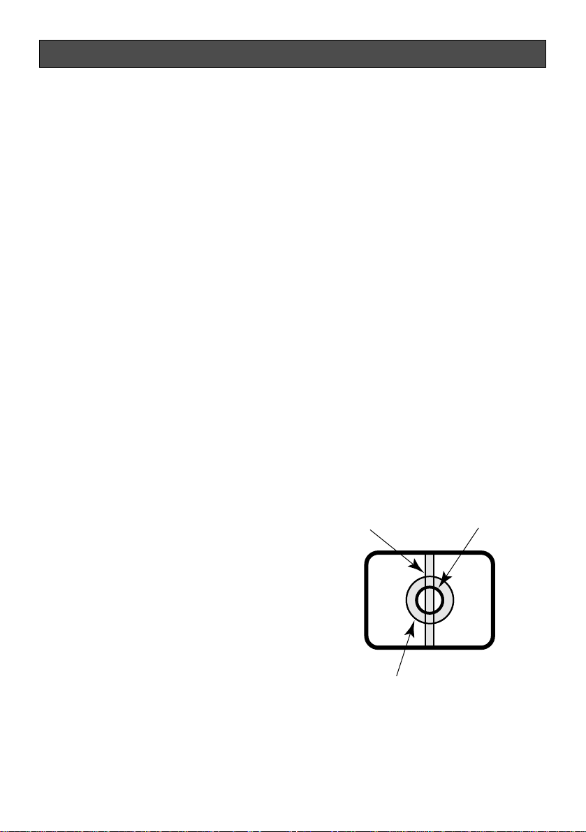
Do not aim the camera at strong light
sources.
A light source such as a spot light causes a
blooming (light bleeding) or a smear (vertical
lines).
Smear
Bright subject
Blooming

8
Use this product for indoor use only.
Do not expose this product to direct sunlight
for hours and do not install the product near
a heater or an air conditioner. Otherwise, it
may cause deformation, discoloration and
malfunction. Keep this product away from
water.
Avoid installing in the following locations.
• Locations where it may get wet from rain
or water splash
• Locations where a chemical agent is
used such as a swimming pool (not only
outdoor)
• Locations subject to steam and oil smoke
such as a kitchen
• Locations near flammable gas or vapor
• Locations where radiation or x-ray emissions are produced
• Locations subject to strong magnetic
field or radio waves
• Locations where corrosive gas is produced
• Locations where it may be damaged by
briny air such as seashores
• Locations where the temperature is not
within –10 °C - +50 °C {14 °F - 122 °F}.
• Locations subject to vibrations (This
product is not designed for on-vehicle
use.)
Installing place
Contact your dealer for assistance if you are
unsure of an appropriate place in your particular environment.
Make sure that the installation area is strong
enough to hold the camera, such as a concrete ceiling.
Do not install the camera in a humid or
dust-laden environment.
Otherwise, lifetime of the internal parts may
be shortened.
Be sure to remove this product if it is not
in use.
Radio interference
When the camera is used near TV/radio
antenna, strong electric field or magnetic
field (near a motor or a transformer), images
may be distorted and noise sound may be
produced.
Mounting screws
It is necessary to procure screws or bolts to
mount the camera. Prepare them according
to the material and strength of the area
where the camera is to be installed. The
screws and bolts must be tightened with an
appropriate tightening torque according to
the material and strength of the installation
area.
9
Major Operating Controls and Their Functions
TOP
LOCK
B.S BLC
ALC
ELC
D/N
ON
OFF
AF
MONITOR
q
!3
!2
!1
!0
o
i
u
w
e
r
t
y
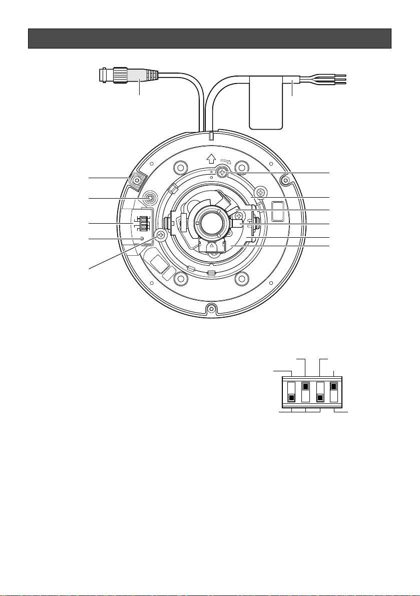
q Video output connector
Composite video signals are transmitted.
If this unit is connected to the multiplex
unit, the multiplexed VD2 that is prioritized over INT is automatically selected.
w AF switch [ONE PUSH AF]
Refer to the page 14.
e Monitor output jack (RCA jack)
[MONITOR]
Connects the LCD monitor and such
devices for checking images.
r Dip switch
Selects ON/OFF of light control mode,
backlight compensation, Adaptive Black
Stretch or Simple day/night mode.
• Simple day/night mode selector [D/N]
ON: The camera selects black-and-
white mode if the picture is dark, or
color mode if the picture is bright
enough.
OFF: Color picture is displayed normal-
ly.
Default setting: OFF
Note: The simple day/night function is
established by utilizing the SENSE
UP function for B/W images. The IR
filter is secured.
B.S.
D/N
ON
OFF
BLC
ALC
ELC

• Adaptive Black Stretch selector [B.S.]
ON: The dark area of the object is auto-
matically corrected to lighten it.
OFF: Does not compensate.
Default setting: ON
Important: In the case of "ON" setting,
noise may be increased in the dark
area of the object.
In addition, darkness and brightness
may be emphasized in the vicinity of
the boundary between the dark and
bright areas.
•
Backlight compensation selector [BLC]
ON: Compensates the background auto-
matically if it is brighter than the
object.
OFF: This mode is used when the front
of the object is extremely bright.
Default setting: OFF
Note: Under conditions such as
extremely strong backlight, the
desired compensation effect may
not be achieved even with this mode
set to ON to detect the backlight
level.
• Light control mode selector
[ALC/ELC]
ALC: Adjusts the lens iris automatically.
ELC: This mode is used for manual
focus adjustment.
Default setting: ALC
t LED for AF
y Shipping lock screw (blue screw)
Remove this screw before setting the
camera.
u Azimuth adjuster
Adjusts the azimuth angle of the camera.
i Tilting table
Adjusts the tilting position of the camera.
10
o Focus lever
!0 Zoom lock lever
!1 Panning table
Adjusts the panning position of the camera.
!2 Panning table lock screw [LOCK]
Fixes the panning table.
!3 Power cable
Supplies 24 V AC or 12 V DC from an
external power source.
● Direct mounting
If the camera is directly mounted on a
wall/ceiling, align the camera mounting position with the position of the hole through
which the cables run and make the hole.
If no hole is made through a wall/ceiling and
open wiring along a wall/ceiling is used,
process the cover so that the cables can be
run through the side of the cover.
11
Installations and Connections
The following installation should be made by qualified service personnel or system installers.
■ Preparations
Important:
• Procure 4 mounting screws according to the material of the installation area. In this case,
wood screws and nails should not be used.
Recommended tightening torque is as follows.
M4: 1.6 N·m {1.18 lbf·ft}
• Required pull-out capacity of
a single screw/bolt is 196 N
{44.1 lbf} or more.
• If a ceiling board such as
plaster board is too weak to
support the total weight, the
area shall be sufficiently reinforced.
• The protection sheet attached
to the dome cover shall be
peeled off after installation.
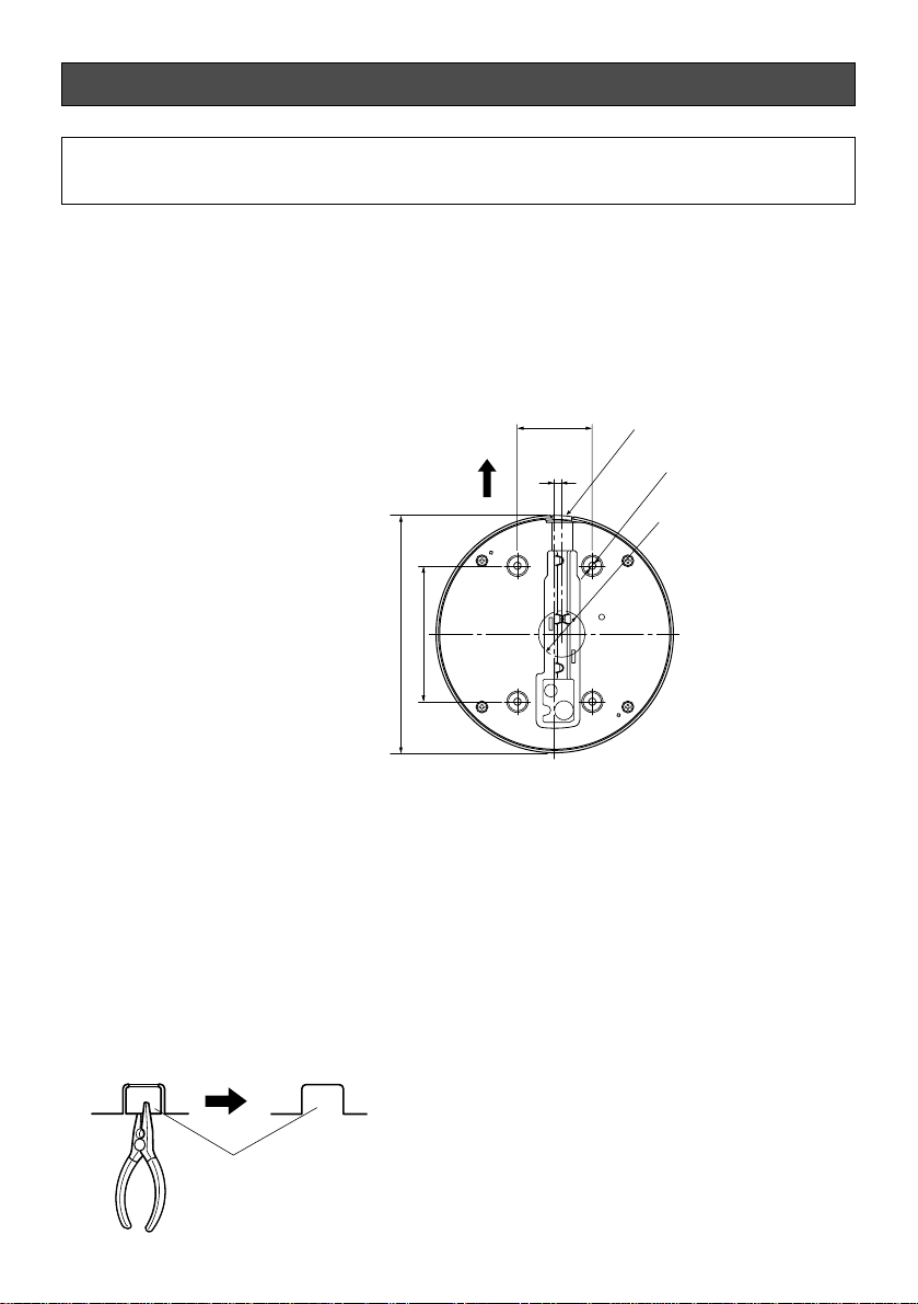
● Using a two-gang junction box
When using a two-gang junction box (4" x
4"), procure one locally that meets the
dimensions in the figure.
And then, locally procure four cameramounting screws suitable for the installation
surface and structure of the wall/ceiling or
two-gang junction box.
Caution:
ONLY CONNECT THIS TO 24 V AC OR 12 V DC CLASS 2 POWER SUPPLY.
<Back/upper>
83.5mm {3.29"}
ø146mm {5.75"}
46 mm {1.81"}
4.5 mm
{0.18"}
Side cable access hole
Camera fixing hole
ø4 - 4.5 mm {0.16" - 0.18"}
Cable access hole
for wall/ceiling
ø30 - 50 mm {1.18" - 1.97"}
Processed section of the side
surface of the cover
 Loading...