

Page 1

Color CCTV Camera
WV-CF254
Before attempting to connect or operate this product, please read these instructions completely
Page 2
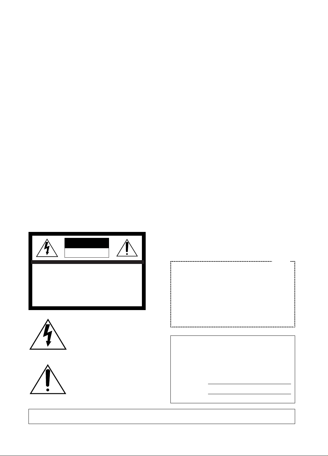
WARNING:
TO PREVENT FIRE OR ELECTRIC SHOCK HAZARD, DO NOT EXPOSE THIS APPLIANCE TO RAIN OR MOISTURE.
The lightning flash with arrowhead
symbol, within an equilateral triangle,
is intended to alert the user to the
presence of uninsulated "dangerous
voltage" within the product's enclosure that may be of sufficient magnitude to constitute a risk of electric
shock to persons.
The exclamation point within an equilateral triangle is intended to alert the
user to the presence of important
operating and maintenance (servicing) instructions in the literature
accompanying the appliance.
The serial number of this product may be found on the
top of the unit.
You should note the serial number of this unit in the
space provided and retain this book as a permanent
record of your purchase to aid identification in the event
of theft.
Model No.
Serial No.
Warning:
This equipment generates and uses radio frequency
energy and if not installed and used properly, i.e., in
strict accordance with the instruction manual, may
cause harmful interference to radio communications.
It has been tested and found to comply with the limits
for a Class A computing device pursuant to Subpart J
of Part 15 of FCC Rules, which are designed to provide reasonable protection against such interference
when operated in a commercial environment.
CAUTION:
TO REDUCE THE RISK OF ELECTRIC SHOCK, DO
NOT REMOVE COVER (OR BACK). NO USER SERVICEABLE PARTS INSIDE.
REFER SERVICING TO QUALIFIED SERVICE PERSONNEL.
CAUTION
RISK OF ELECTRIC SHOCK
DO NOT OPEN
SA 1965
SA 1966
For U.S.A
Page 3

-1-
CONTENTS
PREFACE ............................................................................................................................................................ 2
FEATURES .......................................................................................................................................................... 2
PRECAUTIONS ................................................................................................................................................... 2
MAJOR OPERATING CONTROLS AND THEIR FUNCTIONS ............................................................................. 3
CONNECTIONS .................................................................................................................................................. 5
INSTALLATION ..................................................................................................................................................... 6
ADJUSTMENT ....................................................................................................................................................... 9
SYSTEM CONNECTION ...................................................................................................................................... 11
SETUP ................................................................................................................................................................. 12
1. CAMERA SETUP MENU ............................................................................................................................... 12
2. SETUP OPERATION ..................................................................................................................................... 12
SETTING PROCEDURES .................................................................................................................................... 15
PREVENTION OF BLOOMING AND SMEAR ...................................................................................................... 20
SPECIFICATIONS ................................................................................................................................................ 21
STANDARD ACCESSORIES ............................................................................................................................... 21
Page 4

-2-
1. The following functions are built in.
(1) Auto Light Control (ALC)/Electronic Light
Control (ELC)
(2) The SUPER-D function eliminates interfer-
ence by strong background lighting which
makes the camera picture dark, such as a
spotlight.
Dynamic range of 40 dB.
(3) Auto/Manual White Balance Function
(4) Electronic Shutter Function
2. Signal-to-noise ratio of 50 dB
3. Minimum illumination of 5 lux (0.5 footcandle).
4. 480 lines of horizontal resolution
5. High quality picture:
(a) 2H type vertical enhancer for greater pic-
ture sharpness
(b) Chroma averaging circuit for better color
signal to noise ratio
(c) Minimum of aliasing on fine objects
(d) Expanded dynamic range by use of knee
circuit
(e) Highlight aperture correction for greater
picture detail of bright object
PREF ACE
Panasonic's WV-CF254 color digital camera introduces a new level of high picture quality and high
resolution through the use of a 1/3-inch interline
transfer CCD image sensor having 771 horizontal
pixels (picture elements), and digital signal processing LSIs. This model offers cutting-edge technology for advanced video surveillance.
FEATURES
1. Do not attempt to disassemble the camera.
To prevent electric shock, do not remove
screws or covers.
There are no user serviceable parts inside. Ask
a qualified service person for servicing.
2. Handle the camera with care.
Do not abuse the camera. Avoid striking,
shaking, etc. The camera could be damaged
by improper handling or storage.
3. Do not expose the camera to rain or
moisture, or try to operate it in wet areas.
Turn the power off immediately and ask a qualified service person for servicing. Moisture can
damage the camera and also create the danger of electric shock.
4. Do not use strong or abrasive detergents
when cleaning the camera body.
Use a dry cloth to clean the camera when
dirty.
In case the dirt is hard to remove, use a mild
detergent and wipe gently.
5. Never face the camera towards the sun.
Do not aim the camera at bright objects.
Whether the camera is in use or not, never aim
it at the sun or other extremely bright objects.
Otherwise, blooming or smear may be caused.
6. Do not operate the camera beyond the
specified temperature, humidity or power
source ratings.
Use the camera under conditions where temperature is between −10°C - +50°C (14°F 122°F), and humidity is below 90%. The input
power source is AC 24 V.
Caution:
To prevent fire or electric shock hazard, a
UL listed wire (VW-1, style 1007) should be
used for AC 24 V Input Terminals.
PRECAUTIONS
Page 5

-3-
MAJOR OPERATING CONTROLS AND THEIR FUNCTIONS
OPEN
LO
CK
UP
LEFT RIGHT
SET
DOWN
K
C
O
L
N
E
P
O
Page 6

-4-
o (S) (Set Button)
This button activates a selected item in the
CAM SETUP menu.
!0 Lens Holders
These holders bring the picture in an upright
position on the monitor screen.
!1 Dome Cover
This protects the camera head.
!2 Video Output Cable with BNC Connector
This connector is used to connect with the
VIDEO IN connector of the monitor.
!3 Power Cable with MOLEX Connector
This cable is for connecting the 24 V AC power
supply cable.
!4 Camera Fixing Bracket
This bracket holds the camera on the ceiling or
the wall.
Cautions:
1. Connect to 24 V AC (19.5 V-28 V) class 2
power supply only. Make sure to connect
the grounding lead to the GND terminal
when the power is supplied from a 24 V AC
power source.
2. To prevent fire or electric shock hazard, use
a UL listed wire VW-1, style 1007 cable for
the Input Terminal.
q Panning Table
This adjusts the panning angle of the camera.
w Camera Head
This adjusts the tilting angle of the camera.
e Focus Ring
This adjusts the focus.
r Zoom Ring
This adjusts the angle of view.
t (D) (Down Button)
This button moves the cursor downward. It
also selects items in the CAM SETUP menu.
y (R) (Right Button)
This button moves the cursor to the right. It
also selects the mode and adjusts some levels.
u (L) (Left Button)
This button moves the cursor to the left. It also
selects the mode and adjusts some levels.
i (U) (Up Button)
This button moves the cursor upward. It also
selects items in the CAM SETUP menu.
Page 7

-5-
CONNECTION
Precaution:
The following connections should be made by qualified service personnel or system installers in accordance with NEC 725-51.
O
PEN
LOCK
To Video IN
(CAMERA IN)
Video Output Cable
24V AC
BNC Plug
BNC
Plug
Coaxial Cable
How to assemble the cable with the accessory
connector
Strip back the cable jacket approx. 3 mm (1/8 inch)
and separate the individual conductors.
Recommended wire gauge sizes for 24 V AC line.
#24
(0.22mm
2
)
Copper wire size
(AWG)
Length
of Cable
(Approx.)
(m)
(ft)
#22
(0.33mm
2
)
#20
(0.52mm2)
#18
(0.83mm2)
20 30 45 75
65 100 160 260
Accessory Connector Information
Pin No. Power Source
1 :
2 :
3 :
4 :
24 V AC LIVE
24 V AC NEUTRAL
Ground
Not used
Prepare the individual conductors for clamping.
Use MOLEX band tool part number 57027-5000
(for UL-Style Cable UL1015) or 57026-5000 (for ULStyle UL-1007) for clamping the contacts.
After clamping the contacts, push them into the
proper holes in the accessory connector of this
camera until they snap in place.
1. Shrinking the cable-entry seal is a one-time
procedure. Do not shrink the cable-entry
seal until it has been ascertained that the
unit is functioning.
CONNECT THIS TO 24V AC CLASS 2
POWER SUPPLY ONLY.
2. To prevent fire or electric shock hazard, the
UL listed wire VW-1 style 1007 should be
used for the cable for 24V AC Input
Terminals.
Up
Wire
Contact
Up
Contact
Wire
Approx.
3 mm (1/8 inch)
Insert the wire until A position
and clamp the contacts.
1
3
2
4
• Power supply connection
CAUTIONS
A
Insert
Page 8

-6-
INSTALLATION
Important Notices:
• The following installation should be made by
qualified service personnel or system installers
and should confirm to all local codes.
• Be sure to use a ceiling board having enough
strength to support this camera.
1. Mounting the camera fixing bracket
1-1. Make a hole (diameter 75mm) in the ceiling
board in the desired location.
1-2. Fix the camera fixing bracket onto the ceiling
board by using four camera fixing bracket
mounting screws (not provided).
Note:
Before fixing the bracket with screws, confirm
the direction of the camera by checking the
position of signs “FRONT g UPPER” and
“REAR g LOWER” on the camera fixing brack-
et.
“FRONT g UPPER” sign indicates the direction of the camera head.
“REAR g LOWER” sign indicates the direction
opposite to the camera head.
2. Mounting the camera onto the camera
fixing bracket
2-1. Make sure the video output cable and power
cable are fixed by the coaxial cable clamps.
2. Pass the video output cable and power cable
through the hole in the camera fixing bracket,
and connect as described in the previous section “CONNECTION.”
REAR LOWER
FRONT UPPER
O
P
E
N
LO
C
K
ø75 mm (ø2-15/16”)
Mounting hole
Ceiling board
Coaxial cable clamps
Power cable
Video output cable
Mounting screws (not provided)
Ceiling board
Camera
fixing angle
Page 9

-7-
Notes:
• If the camera body is not installed correctly in
the camera fixing bracket, the fall prevention
cap cannot be inserted.
• The camera body cannot be moved after the
fall prevention cap is installed.
• When you need to remove the camera body,
first remove the fall prevention cap.
O
P
E
N
L
O
C
K
OPEN
LOCK
2-3. Remove the dome cover from the camera by
turning it counterclockwise.
2-4. Match the slit in the camera fixing bracket with
the lock line on the camera, and mount the
camera onto the camera fixing bracket.
2-5. Turn the camera in the LOCK direction until the
lock tab of the camera fixing bracket meets the
lock line of the camera.
OPEN
LO
CK
OPEN
LO
CK
2-6. Attach the fall prevention cap on the lock tab
of the camera fixing bracket as shown below to
prevent the camera from falling down.
OPEN
L
O
C
K
Slit
Lock
line
Lock tab
Lock line
Page 10

-8-
2-7. Match the four grooves on the camera with the
four projections on the dome cover.
2-8. Attach the dome cover to the camera by turn-
ing this cover clockwise so that the window in
the dome cover matches the camera head.
O
P
E
N
LOCK
O
P
E
N
LOCK
Grooves
Projections
Page 11

-9-
ADJUSTMENT
1. Panning
The Panning table can be moved between the
guide lines.
2. Tilting the camera
The tilting angle is shown below.
Note: Uprighting the picture on the monitor screen
is usually necessary. (Refer to 3. Uprighting
the picture.)
S
U
P
E
R
D
Y
N
A
M
I
C
S
U
P
E
R
D
Y
N
A
M
I
C
OPEN
L
O
C
K
4. Focusing
Precaution:
The focus adjustment should be done at
the same time as the camera angle adjustment.
Lens holders
3. Uprighting the picture
Loosen the 2 lens holders and bring the picture in an upright position on the monitor
screen by turning the camera head.
Guide lines
Panning table
77.5° (max)
4-1. Loosen the zoom lock lever.
4-2. Set the angular field of view according to the
scene desired.
4-3. After setting the angular field of view, tighten
the zoom lock lever.
4-4. Loosen the focus lock lever.
OPEN
L
O
C
K
Focus lock lever
Zoom lock lever
Focus ring
Page 12

-10-
O
P
E
N
LOCK
4-5. Set the correct focus by turning the focus ring.
4-6. After setting the correct focus, tighten the
focus lock lever.
4-7. After adjusting the angular field of view and
focus, attach the dome cover to the camera
body.
Page 13

-11-
SYSTEM CONNECTION
4
8
12
16
3
7
11
15
2
6
10
14
1
5
9
13
PUSH OPEN
16
POWER
LOCK
ON
OFF
ALARM
MULTI
SCREEN
MULTISCREEN
SELECT
RESET SPOT SEQUENCE
VCR
CAM
CAMERA/PRESET POSITION
Video Multiplexer
Time Lapse VCR
Spot Monitor
Live 1-16ch
Multiscreen Monitor
Live 1-16ch
Playback 1-16ch
RS-232C/Wired
AUX
Alarm
OPEN
LOCK
Shown below is an example of a basic system connection.
Page 14

1. CAMERA SETUP MENU
This camera utilizes a user setup menu that is displayed on-screen.
The setup menu contains various items that form a tree-type structure as shown below.
It is described in the following section : “2. SETUP OPERATION.”
-12-
CAM SETUP
Camera
ID
ON/OFF
Camera
ID
Editing
SUPER-D
ON
Camera ID
Display
Position
Manual
Level
Selection
SUPER-D
OFF
Light
Control
ALC ELC
Manual
Mask Area
Selection
Manual
Level
Selection
INT
Manual
Selection
Shutter
Speed
AGC
ON/OFF
Manual
Mask Area
Selection
V. Phase
Manual
Adjustment
SYNC
INT/LL
LL
Manual
Selection
VD2
Automatic
Selection
SETUP DISABLE → SETUP ENABLE →
SETUP
Left Button
Set Switch
Right Button
Down Button
Up Button
(U) (Up Button):
This button is used to move the cursor
upwards. Use this button to select an item
or adjust the parameters.
(D) (Down Button):
This button is used to move the cursor
downwards. Use this button to select an
item or adjust the parameters.
(R) (Right Button):
This button is used to move the cursor to
the right. Use this button to select or adjust
the parameters of the selected item. The
parameter changes each time this button is
pressed.
(L) (Left Button):
This button is used to move the cursor to
the left. Use this button to select or adjust
the parameters of the selected item. The
parameter changes each time this button is
pressed.
(S) (Set Button):
This button is used to set the determined
parameter. If the item has its own setting
menu (as indicated by ), press this button to display the setting menu.
• All Reset Operation
All Reset allows you to reset all setup menu items
to the factory settings if you are unsure about the
correct settings. Proceed as follows:
(1) Make sure that the CAM SETUP menu is not
displayed (a camera picture is displayed).
(2) While pressing both (L) and (R), press
(S) for a few seconds. The words ALL
RESET momentarily appear on the monitor.
At this time all adjustments and parameters are
reset to the factory default settings.
2. SETUP OPERATION
This camera utilizes a user setup menu (CAM
SETUP) that is displayed on the monitor.
To set items on the CAM SETUP menu, use the following buttons on the side panel.
Page 15

-13-
Manual
Level
Adjustment
Special
menu
Chroma
Gain
AP
Gain
Pedestal Hue
Manual
Level
Adjustment
Manual
Mask Area
Selection
Manual
Mask Area
Selection
White
Balance
ATW AWC
** CAM SET UP **
CAMERA ID OFF
ALC/ELC ALC
SHUTTER --AGC ON
SYNC INT
WHITE BAL ATW
END SET UP DISABLE
↵↵↵
The CAM SETUP menu appears on the monitor as
shown above.
Check the current settings on the menu.
Refer to the sections below for a detailed description of menu items. If you decide not to make any
changes after checking the current settings, move
the cursor to END at the start of the bottom line,
and press (S) to close the CAM SETUP menu
and return to normal camera picture mode.
Note: If no button is pressed for 6 minutes while
the CAM SETUP menu or any other setting
menu is displayed, displaying the menu is
automatically canceled and the mode returns
to the normal camera picture.
• Opening the Setup Menu
Press and hold down (S) for a second or longer.
• Editing the CAM SETUP Menu
Important Notice:
When the words SETUP DISABLE appear on
the bottom line of the CAM SETUP menu, you
cannot change the currently active settings.
This is to prevent accidental changing of the
settings.
To edit the CAM SETUP menu (change settings),
use (U) and (D) or (L) and (R) to
move the cursor to SETUP DISABLE in the bottom
line.
Press (S). SETUP DISABLE changes to SETUP
ENABLE. Move the cursor to END, then to the
item(s) you want to change.
** CAM SET UP **
CAMERA ID OFF
ALC/ELC ALC
SHUTTER --AGC ON
SYNC INT
WHITE BAL ATW
END SET UP DISABLE
↵↵
Blinking
Page 16

-14-
• Editing the SPECIAL menu
To edit the SPECIAL menu (change settings), proceed as for editing the CAM SETUP menu above.
Move the cursor to END after the words SETUP
ENABLE appear. Then press (L) and (R)
simultaneously for 2 seconds or longer.
The SPECIAL menu appears on the monitor. Select
the item to be changed and change the setting as
described for the CAM SETUP menu.
Important Notice:
When the cursor is moved to END and the
CAM SETUP menu closed after changing the
parameters, the new values are stored in the
EEPROM (Electric Erasable and Programmable Read Only Memory). These values
remain valid until new values are stored, even
if the power of the camera is off.
** CAM SET UP **
CAMERA ID OFF
ALC/ELC ALC
SHUTTER --AGC ON
SYNC INT
WHITE BAL ATW
END SET UP DISABLE
↵↵↵
** CAM SET UP **
CAMERA ID OFF
ALC/ELC ALC
SHUTTER --AGC ON
SYNC INT
WHITE BAL ATW
END SET UP ENABLE
↵↵↵
** SPECIAL **
CHROMA GAIN ....I....
AP GAIN ....I....
PEDESTAL .I.......
HUE .I.......
- +
CAMERA RESET PUSH SW
RET END
Page 17

-15-
1. Camera Identification (CAMERA ID)
Setting
You can use the camera identification (CAMERA
ID) to assign a name to the camera. The camera ID
consists of up to 16 alphanumeric characters. You
can select whether to have the camera ID displayed on the monitor screen or not.
To edit the CAMERA ID
1. Move the cursor to the CAMERA ID parameter.
2. Press (S). The CAMERA ID menu appears.
The cursor on the letter “0” starts blinking.
3. Move the cursor to the character you want to
change by pressing (L)/ (R)/ (U)/
(D).
4. After selecting the character, press (S).
The selected character appears in the editing
area. (The pointer in the editing area moves to
the right automatically at this moment.)
5. Repeat the steps above until all characters are
edited.
To enter a blank space in the CAMERA ID
Move the cursor to SPACE and press (S).
To edit a specific character in the CAMERA ID
1. Move the cursor to the editing area by pressing (S).
2. Move the pointer to the character to be edited
by pressing (L) or (R). Then move the
cursor to the character area and select a new
character.
3. Press (S) to determine the CAMERA ID.
Character Cursor
Pointer
Character
Area
Command
Editing
Area
CAMERA ID menu
** CAM SET UP **
CAMERA ID OFF
ALC/ELC ALC
SHUTTER --AGC ON
SYNC INT
WHITE BAL ATW
END SET UP ENABLE
↵↵↵
0123456789
ABCDEFGHIJKLM
NOPQRSTUVWXYZ
().,'":;&#!?=
+-*/%$
SPACE
POSI RET END RESET
................
SETTING PROCEDURES
To erase all characters in the editing area
Move the cursor to RESET and press (S). All
characters in the editing area disappear.
To determine the display position of the
CAMERA ID
1. Move the cursor to POSI, and press (S).
The display shown below appears and the
CAMERA ID starts blinking.
Blinking
2. Move the CAMERA ID to the desired position
by pressing (L)/ (R)/ (U)/ (D).
3. Press (S) to fix the position of the CAMERA
ID. The mode returns to the previous CAMERA
ID menu.
Notes:
• The CAMERA ID stops at the edges of the
monitor screen.
• The CAMERA ID moves faster if any of
(L)/ (R)/ (U)/ (D) is kept
pressed for a second or longer.
To return to the CAM SETUP menu
Move the cursor to RET and press (S). The
CAM SETUP menu appears.
2. Light Control Setting (ALC/ELC)
You can select one of the following light control
modes:
ALC: This camera has an ALC lens..
ELC: If you select this mode, the iris is kept open.
Select a SHUTTER parameter to control the
brightness.
1. Move the cursor to the ALC/ELC parameter.
2. Select ALC or ELC.
WV-CF254
** CAM SET UP **
CAMERA ID OFF
ALC/ELC ALC
SHUTTER --AGC ON
SYNC INT
WHITE BAL ATW
END SET UP ENABLE
↵↵↵
Page 18

-16-
2-1. ALC Mode with SUPER-D ON
Super Dynamic Function (SUPER-D)
The important object in a scene is usually placed in
the center of the monitor’s screen. In SUPER-D
mode, more photometric weight is given to the center of the screen (where the important object is
located) than to the edge of the picture (where a
bright backlight would most likely be located). You
can use the SUPER-D function if you select ALC. It
eliminates interference by strong background lighting which makes the camera picture dark, such as
a spotlight.
1. Press (S) after selecting ALC. The ALC
CONT menu appears.
2. Move the cursor to the SUPER-D parameter
and select ON.
3. If you want to adjust the video output level,
move the cursor to the “I” position. Adjust to
the desired level by pressing (L) or
(R).
4. Move the cursor to RET and press (S) to
return to the CAM SETUP menu. (To return to
the camera picture, move the cursor to END
and press (S).)
** CAM SET UP **
CAMERA ID OFF
ALC/ELC ALC
SHUTTER --AGC ON
SYNC INT
WHITE BAL ATW
END SET UP ENABLE
↵↵↵
** ALC CONT **
BACK LIGHT COMP
SUPER-D OFF
MASK SET
LEVEL ...I.....
- +
RET END
↵
** ALC CONT **
BACK LIGHT COMP
SUPER-D ON
LEVEL ...I.....
- +
RET END
2. Move the cursor to MASK SET and press
(S). The 48 mask areas appear on the monitor
screen. The cursor is blinking in the top left
corner of the screen.
3. Move the cursor to the area where backlight is
bright and press (S) to mask that area.
The mask turns white. (When the cursor is
moved on an area that has already been
masked, the mask and cursor start blinking.)
Blinking
Blinking
2-2. ALC Mode with SUPER-D OFF and ELC
Mode
Note: If ELC is selected, set MASK SET according
to this procedure.
1. Move the cursor to the SUPER-D parameter
and select OFF. (When you select ELC,
SUPER-D is not available.) The item MASK SET
appears on the menu.
** ALC CONT **
BACK LIGHT COMP
SUPER-D OFF
MASK SET
LEVEL ...I.....
- +
RET END
↵
Page 19

-17-
4. Repeat step 1 to 3 to mask the desired areas.
To cancel masking, move the cursor to that
area and press (S).
5. After masking is completed, press (S) for 2
seconds or longer. The ALC CONT menu
appears.
6. If you want to change the video output level
(picture contrast), move the “I” cursor to
LEVEL and adjust the level.
7. Move the cursor to RET and press (S) to
return to the CAM SETUP menu. (To return to
the camera picture, move the cursor to END
and press the set button.)
3. Shutter Speed Setting (SHUTTER)
Note: When ON is selected for SUPER-D on the
ALC CONT menu, this item is not available.
To select electronic shutter speed, select OFF
for SUPER-D in the menu.
You can select an electronic shutter speed of 1/60
(OFF), 1/100, 1/250, 1/500, 1/1 000, 1/2 000, 1/4 000,
or 1/10 000 seconds.
Blinking
Turns to white
Move the cursor to the SHUTTER parameter and
select the electronic shutter speed.
The preset values for SHUTTER (electronic shutter
speed) change by pressing (L) or (R) as
follows:
** CAM SET UP **
CAMERA ID OFF
ALC/ELC ALC
SHUTTER --AGC ON
SYNC INT
WHITE BAL ATW
END SET UP ENABLE
↵↵↵
OFF (1/60) 1/100
1/10000 1/4000 1/2000 1/1000
1/250 1/500
4. Gain Control Setting (AGC ON/OFF)
You can set the gain (brightness level portion of an
image) to automatic level adjustment (ON) or fixed
level (OFF).
Move the cursor to the AGC parameter and select
automatic level adjustment (ON) or fixed level
(OFF).
5. Synchronization Setting (SYNC)
You can select internal sync mode (INT) or line-lock
mode (LL). The VD2 signal (multiplexed vertical
drive signal) with the composite video output signal
from external equipment such as a Matrix Switcher
is also acceptable.
Whenever the VD2 signal is supplied to this camera, the camera automatically switches to the VD2
sync mode.
1. Move the cursor to the SYNC parameter and
select line-lock (LL) or internal (INT).
2. Press (S).
If LL is selected, the SYNC menu appears. (If
INT is selected, the synchronization mode is
automatically set to internal sync pulse, and
the menu is not displayed.)
** CAM SET UP **
CAMERA ID OFF
ALC/ELC ALC
SHUTTER --AGC ON
SYNC INT
WHITE BAL ATW
END SET UP ENABLE
↵↵↵
** CAM SET UP **
CAMERA ID OFF
ALC/ELC ALC
SHUTTER --AGC ON
SYNC INT
WHITE BAL ATW
END SET UP ENABLE
↵↵↵
Important Notices:
1. The priority for the sync modes is as follows.
1. Multiplexed Vertical Drive (VD2) (Highest
priority)
2. Line-lock (LL)
3. Internal Sync (INT) (Lowest priority)
2. The line-lock mode has its own menu for linelock vertical phase adjustment. If the camera
installation is relocated, check the vertical
phase adjustment again since the AC line
phase may be different.
Page 20

-18-
5-1. Line-lock Sync Mode (LL)
1. Move the cursor to the SYNC parameter and
select LL.
Note: The settings in this menu can be made
only when the multiplexed vertical drive
signal (VD2) is not supplied to the camera.
2. After confirming the cursor is on LL, press
(S). The vertical phase adjustment menu
appears on the monitor.
3. Move the cursor to COARSE. The cursor starts
blinking.
4. Supply the video output signal of the camera
to be adjusted and the reference camera video
output signal to a dual-trace oscilloscope.
5. Set the oscilloscope to the vertical rate and
expand the vertical sync portion on the oscilloscope.
6. Press (L ) or (R) to match the vertical
phase for both video output signals as closely
as possible. (COARSE adjustment can be incremented in 16 steps by 22.5 degrees by pressing (L) or (R).)
** SYNC **
V PHASE
COARSE 1(1--16)
FINE I........
- +
RET END
Note: After the sixteenth step, the adjustment
returns to the first step.
7. Move the cursor to FINE. The cursor starts
blinking.
8. Press (L) or (R) to match the vertical
phase for both video output signals as closely
as possible.
(FINE adjustment can be made up to 22.5
degrees by pressing (L) or (R).)
Notes:
• When the “I” cursor reaches the “+” end, it
jumps back to “−”. At the same time,
COARSE is incremented by one step to
enable a continuous adjustment. The
reverse takes place when the “I” cursor
reaches the “−” end.
• When (L) or (R) is kept pressed
for a second or longer, the “I” cursor
moves faster.
• To reset COARSE and FINE to the values
preset at the factory, press (L) or
(R) simultaneously. COARSE and FINE
adjustments are preset at the factory to
zero-crossing of the AC line phase.
• If the AC line contains noise (spike noise,
etc.), the stability of the vertical phase of
the camera video output signal may be
disturbed.
6. White Balance Setting (WHITE BAL)
You can select one of two modes for white balance
adjustment as follows:
• ATW (Auto Tracing White Balance)
In this mode, the color temperature is monitored
continuously and thereby white balance is set
automatically. The color temperature range for
the proper white balance is approximately
2 600 - 6 000K. Proper white balance may not
be obtained under the following conditions:
1. The color temperature is out of the 2 600 6 000K range.
2. When the scene contains mostly high
color temperature objects, such as a blue
sky or sunset.
3. When the scene is dim.
In these cases, select the AWC mode.
Move the cursor to the WHITE BAL parameter
and select ATW. The white balance of the
camera is automatically set.
1 (1 - - 16): 0 degrees
2 (1 - - 16): 22.5 degrees
16 (1 - - 16): 337.5 degrees
** CAM SET UP **
CAMERA ID OFF
ALC/ELC ALC
SHUTTER --AGC ON
SYNC INT
WHITE BAL ATW
END SET UP ENABLE
↵↵↵
Page 21

-19-
•
AWC (Automatic White Balance Control)
In this mode, accurate white balance is
obtained within a color temperature range of
approximately 2 300-10 000K.
1. Move the cursor to the WHITE BAL parameter
and select AWC → PUSH SW.
2. Press (S) to start the white balance setup.
The words PUSH SW start blinking to indicate
that the white balance is being set.
Blinking
** CAM SET UP **
CAMERA ID OFF
ALC/ELC ALC
SHUTTER --AGC ON
SYNC INT
WHITE BAL AWC
→
PUSH SW
END SET UP ENABLE
↵↵
** CAM SET UP **
CAMERA ID OFF
ALC/ELC ALC
SHUTTER --AGC ON
SYNC INT
WHITE BAL AWC
→
PUSH SW
END SET UP ENABLE
↵↵
3. When the white balance setting is completed,
the words PUSH SW stop blinking.
4. When you want to adjust the white balance
manually, press (R) to select AWC and
press (S). The AWC menu appears on the
monitor. (When ATW is selected, pressing
(S) displays the ATW menu.)
** CAM SET UP **
CAMERA ID OFF
ALC/ELC ALC
SHUTTER --AGC ON
SYNC INT
WHITE BAL AWC
END SET UP ENABLE
↵↵↵
** AWC **
R ....I....
- +
B ....I....
- +
MASK SET
RET END
↵
Manual Fine Adjustment of AWC (ATW)
You can set details for white balance manually.
1. To set MASK SET, proceed as described in
steps 1 to 4 of “ALC mode with SUPER-D OFF
and ELC mode” on page 16.
2. Move the cursor to R.
3. Press (L) or (R) to obtain the optimum
amount of red gain.
4. Move the cursor to B.
5. Press (L) or (R) to obtain the optimum
amount of blue gain.
Note: When you need to set MASK SET, re-adjust
to obtain the optimum amount of red and blue
gain.
7. Special Menu (SPECIAL)
This menu lets you adjust and set up the video signal of the camera to meet your requirements.
Move the cursor to END on the bottom line of the
CAM SETUP menu and press (L) or (R)
simultaneously for 2 seconds or longer. The SPECIAL menu appears on the monitor as shown
below.
** CAM SET UP **
CAMERA ID OFF
ALC/ELC ALC
SHUTTER --AGC ON
SYNC INT
WHITE BAL ATW
END SET UP DISABLE
↵↵↵
** SPECIAL **
CHROMA GAIN ....I....
AP GAIN ....I....
PEDESTAL .I.......
HUE .I.......
- +
CAMERA RESET PUSH SW
RET END
7-1. Chroma Level Setting (CHROMA GAIN)
1. Move the cursor to the CHROMA GAIN parameter.
2. While observing the vectorscope or color video
monitor, move the “I” cursor to adjust the chroma level.
7-2. Aperture Gain Setting (AP GAIN)
1. Move the cursor to the AP GAIN parameter.
2. While observing the vectorscope or video
monitor, move the “I” cursor to adjust the aperture gain level.
7-3. Pedestal Level Setting (PEDESTAL)
1. Move the cursor to the PEDESTAL parameter.
2. While observing the waveform monitor/oscilloscope or video monitor, move the “I” cursor to
adjust the pedestal level (black level).
7-4. Chroma Phase (Hue) Setting (HUE)
1. Move the cursor to the HUE parameter.
2. While observing the vectorscope or color video
monitor, move the “I” cursor to adjust the hue
(chroma phase) level.
To reset to the factory settings
1. Move the cursor to the CAMERA RESET parameter. The words PUSH SW start blinking.
2. While holding down (L) and (R), press
(S) for 2 seconds or longer. The camera is
reset to the factory settings.
Page 22

-20-
To close the SPECIAL menu and return to the
CAM SETUP menu
Move the cursor to RET and press (S).
To close the SPECIAL menu and return to the
camera picture
Move the cursor to END and press (S).
When the camera is aimed at a bright light, such as
a spotlight, or a surface that reflects bright light,
smear or blooming may appear. Therefore, the
camera should be operated carefully in the vicinity
of extremely bright objects to avoid smear or
blooming.
Bright object
Smear
PREVENTION OF BLOOMING AND SMEAR
Page 23

-21-
Pick-up Device: 771 (H) x 492 (V) pixels, Interline Transfer CCD
Scanning Area: 4.8 (H) x 3.6 (V) mm (Equivalent to scanning area of 1/3” pick-up tube)
Scanning: 525 lines / 60 fields / 30 frames
Horizontal: 15.734 kHz
Vertical: 59.94 Hz
Synchronization: Internal, Line-locked, Multiplexed Vertical Drive (VD2) Selectable
Video Output: 1.0 V[p-p] NTSC composite 75 Ω / BNC connector
Horizontal Resolution: 480 lines
Signal-to-Noise Ratio: 50 dB (AGC OFF, weight ON)
Dynamic Range: 40 dB
Minimum Illumination: 5 lx (0.5 footcandle) at WIDE end
Angular Field of View: Horizontal; 41.5° (TELE) - 76.7° (WIDE)
Vertical; 31.9° (TELE) - 59.8° (WIDE)
Gain Control: Selectable AGC ON or OFF (SETUP MENU)
White Balance: Selectable ATW or AWC (SETUP MENU)
Aperture: Variable (SETUP MENU)
Electronic Light Control: Equivalent to continuously variable shutter speed between 1/60 second
and 1/10 000 second
Super-D: Selectable On or Off (SETUP MENU)
Electronic Shutter Speed: Selectable 1/60 (OFF), 1/100, 1/250, 1/500, 1/1 000, 1/2 000, 1/4 000,
1/10 000 second
Ambient Operating Temperature: −10°C - +50°C (14°F - 122°F)
Ambient Operating Humidity: Less than 90%
Power Source: 24V AC 60 Hz, 4.6 W
Dimensions: 143.5 (H) x 121 (D) mm [5-5/8” (H) x 4-3/4” (D)]
Weights: 1.1
kg (2.4 lbs.)
Weights and dimensions indicated are approximate.
Specifications are subject to change without notice.
SPECIFICATIONS
STANDARD ACCESSORIES
Camera Fixing Bracket...............................................................1
Page 24

N1297-0 YWV8QA4878AN Printed in Japan
N 30
Video Imaging Systems Company
A Division of Panasonic Broadcast & Television Systems Company
A Unit of Matsushita Electric Corporation of America
Executive Office: One Panasonic Way 3E-7, Secaucus, New Jersey 07094
Regional Offices:
Northeast: 43 Hartz Way, Secaucus, NJ 07094 (201) 348-7303
Southeast: 1225 Northbrook Parkway, Suite 1-160, Suwanee, GA 30174 (770) 338-6835
Midwest: 1707 North Randall Road, Elgin, IL 60123 (847) 468-5200
Southwest: 8105 Beltsline Road, Suite 100. Irving TX 75063 (214) 915-1333
Western: 6550 Katella Ave., Cypress, CA 90630 (714) 373-7265
PANASONIC CANADA INC.
5770 Ambler Drive, Mississauga, Ontario, L4W 2T3 Canada (905)624-5010
PANASONIC SALES COMPANY
DIVISION OF MATSUSHITA ELECTRIC OF PUERTO RICO, INC.
San Gabriel Industrial Park, 65th Infantry Ave. KM. 9.5 Carolina, P.R. 00630 (809)750-4300
 Loading...